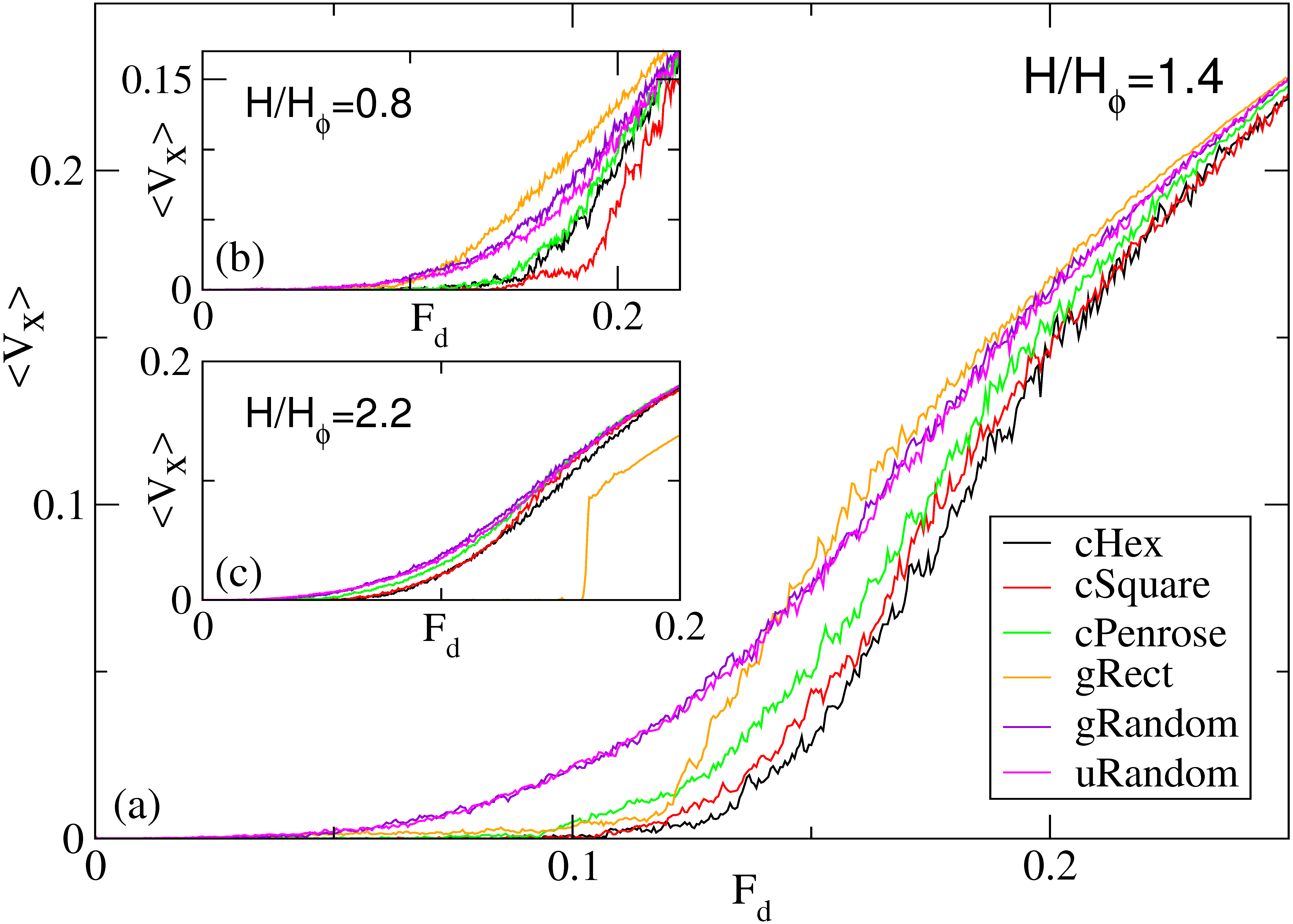
Physical Review B 90, 094502 (2014)

Pinning, Ordering, and Dynamics of Vortices in Conformal Crystal and Gradient Pinning Arrays

D. Ray, C. Reichhardt, and C. J. Olson Reichhardt

Theoretical Division, Los Alamos National Laboratory, Los Alamos, New Mexico 87545, USA

(Received 1 August 2014; published 8 September 2014)

We numerically investigate magnetization, pinning, ordering, and dynamics of vortices interacting with pinning arrangements which have a density gradient. We focus on conformal crystal structures obtained by conformally transforming a spatially uniform periodic array, as well as non-conformal gradient structures and structures with quasiperiodic order. The conformal structures feature a density gradient and local ordering. Using magnetization simulations we find that conformal pinning arrays exhibit enhanced pinning compared to non-conformal gradient arrays as well as compared to random, periodic, and quasiperiodic arrays, for a broad range of fields. The effectiveness of conformal arrays arises from the continuum of length scales introduced into the arrays by the conformal transformation, allowing for a broad range of local commensuration effects. At higher vortex fillings above the range of conformal effectiveness, we show that a non-conformal rectangular gradient array exhibits strong pinning due to a novel commensuration effect and vortex ordering. Using transport simulations where vortices are driven along the gradient and at an angle to the gradient, we confirm the effectiveness of conformal pinning at increasing the critical current. For a rotated drive, the gradient arrays produce a strong vortex guidance effect in the direction perpendicular to the gradient.
I. INTRODUCTION
II. GRADIENT PINNING ARRAYS
A. Conformal arrays
B. Arrays produced by other methods
III. SIMULATION AND SYSTEM
IV. MAGNETIZATION
V. LOCAL COMMENSURATION EFFECT IN CONFORMAL PINNING ARRAYS
VI. RECTANGULAR GRADIENT ARRAY AND COMMENSURATION EFFECTS
VII. CURRENT-DRIVEN RESULTS
A. Drive aligned with gradient
B. Driving in different directions
VIII. SUMMARY
References


I.  INTRODUCTION

One of the most important issues for many applications of type-II superconductors is understanding how to optimize the pinning of magnetic flux vortices, since the system becomes dissipative when vortices are in motion [1]. The applied current at which vortices depin is called the critical current Jc, and there has been intense research in tailoring the pinning in a superconductor so as to maximize Jc for either specific applied fields or for a broad range of fields. Beyond the direct application to superconductivity, vortex pinning and dynamics provide a very rich system for exploring collective ordering of particles on random or periodic substrates, as well as for studying nonequilibrium phenomena at depinning which arise in a variety of condensed matter systems, such as driven charge density waves [2], sliding Wigner crystals [3], atomic friction [4], adhesion [5], magnetic domain wall motion [6], and driven colloidal systems [7].
A widely used method for enhancing the pinning and critical current in superconductors is the creation of nanostructured artificial arrays of pinning sites [8,9,10,11,12,13], featuring a well-defined number of sites arranged in a desired configuration. These sites pin vortices effectively, but only a limited number of sites can be added to a sample since their creation causes local damage to the superconductor that decreases the material's current-carrying capacity. Therefore, it is of great importance to determine the optimal geometrical arrangement of a fixed number of pinning sites that generates the strongest pinning over the widest range of fields. In random site arrangements, where there is a distribution of interpin spacings, the closely-spaced pins are inefficiently used due to strong short-range intervortex repulsion, while widely-spaced pins permit easy flow of vortices between them [14]. Periodic pinning arrays such as triangular or square arrays, which avoid both these shortcomings, have been studied in detail; the pinning is enhanced compared to random arrays, but only near certain commensurate field values, where the number of vortices is an integer [8,9,10,11,12,13,15,16,17] or fractional [18,19] multiple of the number of pinning sites. At commensurability, ordered or partially ordered vortex arrangements form which can have various types of symmetries [9,15,16,17,18,19]; however, away from commensurability, the vortex structures are partially or totally disordered, allowing for the formation of weak spots and easy vortex flow channels which reduce the depinning threshold [9,15,18]. Rectangular pinning arrays that are periodic with two different length scales have been shown to produce anisotropic vortex structures and transport [20,21,22,23,24].
There have been a number of efforts to enhance the pinning in periodic arrays under noncommensurate conditions. Systematically diluting a triangular pinning array gives enhanced pinning not only at matching fields, but also at non-integer matching fields corresponding to what the integer matching fields for the non-diluted array would have been [25,26,27,28,29,30]. Other studies showed that the addition of some disorder to a triangular pinning lattice enhances the pinning at incommensurate fillings, but at the cost of reducing the maximum pinning at the integer matching fields [31]. Asymmetric system geometries, such as funnel geometries [32,33,34] or periodic constriction geometries [35] which utilize vortex jamming, produce new types of commensurability effects. Vortex artificial ice states can be created using superlattices of square pinning arrangements [36,37,38], and exhibit strong matching at certain non-integer fields. Composite pinning lattices based on intermeshed periodic arrays have also been created [39,40,41].
Another approach to pinning enhancement is the use of pinning structures that combine aspects of periodicity and disorder. Studies of quasiperiodic arrays where pinning sites were placed at the vertices of a Penrose tiling [42,43,44,45,46,47,48] revealed novel non-integer matching conditions, and showed that the overall pinning can be enhanced over periodic triangular pinning arrays below the first matching field [42,43,45,47].
Despite these efforts, pinning arrays which rely on commensuration effects have continued to possess the fundamental drawback of only providing enhanced pinning near certain field values, rather than over a broad range of field. In an effort to overcome this shortcoming, a new type of pinning geometry, known as a conformal crystal pinning array, was recently proposed[49]; an example of such an array is shown in Fig. 1(b). A conformal crystal is constructed by performing a conformal, or angle-preserving, transformation upon a uniform lattice structure such as a hexagonal array, producing a new structure which preserves the local ordering of the original array but now exhibits a density gradient in one direction [50,49]. Conformal crystals were first observed as the approximate ground state structure of a set of repulsively interacting magnetic spheres restricted to move in two dimensions and subjected to a gravitational potential; the distinctive arching appearance of the resulting structure inspired the whimsical nickname of "gravity's rainbow" [50]. In vortex simulations, conformal pinning arrays produced enhanced pinning compared to an equivalent number of pinning sites arranged randomly with uniform density over a wide range of applied fields, with the enhancement persisting until the applied field was increased beyond the maximum local pinning density present in the array [49]. The conformal array also outperformed uniform periodic arrays except in the immediate vicinity of the matching field. A random array with a density gradient produced pinning only marginally better than a non-gradient random array and substantially worse than the conformal array, indicating that the preservation of local order was as vital to the conformal array's performance as was the introduction of a gradient. The enhancement was observed both in flux gradient-driven simulations [49], where the vortices enter or exit the system from the edges, and in current-driven simulations [49,51], where the vortex density is fixed and the vortices are driven across the sample with a uniform Lorentz force. Two subsequent experiments confirmed the enhanced pinning in conformal arrays. In the first[52], conformal pinning arrays displayed enhanced critical currents over uniform periodic pinning arrays except in the vicinity of certain matching fields. In the second[53], conformal pinning arrays showed decreased magnetoresistance in transport experiments compared to periodic or diluted periodic structures with the same number of pinning sites.
Pinning arrays with a density gradient not produced by a conformal transformation have also been investigated. A pinning array consisting of concentric rectangular "rings" of pinning sites with a gradually increasing separation between the rings was fabricated and shown to exhibit enhanced pinning compared to a periodic pinning array [54]. Additionally, there have been numerical studies of pinning arrays arranged in circular hyperbolic tessellation structures so that the pinning sites have a gradient [55]; however, these studies did not include comparisons with periodic or random pinning arrays to check whether the hyperbolic array produces enhanced pinning over the other geometries.
In this work, we use molecular dynamics simulations to study magnetization, depinning, ordering and dynamics of vortices in systems with various types of pinning arrays featuring a density gradient. We investigate the effect of different local orderings in conformal crystal arrays by considering transformed versions of hexagonal, square, quasiperiodic, and Archimedean [56,57] lattices. We also consider two non-conformal systems, a rectangular pinning array with a one-dimensional (1D) gradient, and a random pinning arrangement with a density gradient. This manuscript is organized as follows: in Section II, we describe how conformal arrays are created and enumerate the various pinning arrays which will be analyzed. In Section III, we explain our physics model and the types of simulations we perform. In Section IV, we show the results of magnetization simulations, demonstrating that conformal pinning arrays produce enhanced pinning over non-conformal gradient arrays over a wide range of applied fields, as well as over arrays of uniform density such as the quasiperiodic Penrose array or periodic arrays (aside from a narrow range around matching fields). In Section V, by examining the pattern of occupied pinning sites as the field is increased, we show that conformal arrays are effective due to a local commensuration effect which is an extension of the global matching exhibited by uniform pinning arrays: because the conformal transformation introduces a continuously changing lattice constant into the array, the vortex lattice can progressively match with different slices of the array as the number of vortices is increased. Consequently, we find that the particular type of local order present is relatively unimportant in determining the effectiveness of conformal pinning arrays, as long as some type of ordering is present that would give a matching effect in a uniform array. We also use local commensuration to explain the maximum effective field value for conformal arrays. At higher fields well above this value, we show in Section VI that a rectangular gradient pinning array gives enhanced pinning over the conformal arrays due to a novel commensuration effect which gives rise to ordered vortex chain structures. In Section VII, we examine current-driven vortex dynamics for vortices driven along the gradient direction as well as at varied angles with respect to the gradient. We find that in general, conformal pinning arrays reduce vortex motion compared to the other arrays, over the full range of drive angles. Compared to the random and rectangular gradient arrays which exhibit channels of easy vortex flow, the arching structure of the conformal arrays prevents the formation of such channels for any choice of drive angle. Additionally we find that many gradient arrays have a pronounced vortex guidance effect, where vortices move much more easily perpendicular to the gradient than along the gradient. Finally, in Section VIII, we present our conclusions.

II.  GRADIENT PINNING ARRAYS

A.  Conformal Arrays

Conformal transformations are a well-studied topic from complex analysis [58]. An analytic function w=f(z) maps two infinitesimal vectors originating from the same point in the z plane with angle θ between them to two new vectors in the w plane separated by the same angle. We use this property to transform an ordered structure into one which remains locally ordered but which is distorted on a global scale.
Fig1.png
Figure 1: (a) A semiannular section of a uniform hexagonal lattice. (b) Effect of a conformal transformation upon the region in (a). The resulting structure (conformal hex or "cHex") has local hexagonal ordering and a density gradient. See text for details of the transformation.
In this work, we allow the transformation
w= π


+ 1

iα
ln(iαz)
(where α is a constant which we set to π/36) to act on a semiannular section of the z-plane specified by Im z ≥ 0 and rin ≤ |z| ≤ rout for some choice of rin and rout. This transformation maps radial lines in the z plane to vertical lines in the w plane, and circular arcs centered at the origin to horizontal lines. Consequently, the semiannular region ABCDEF is mapped to the rectangle abcdef, as shown in Fig. 1. The circular arcs in the z plane are increasingly stretched by the transformation as their radial coordinate decreases: fixing αrout=1, arc ABC has the same length as line abc, while arc DEF is stretched to the same length as lines def and abc. This increasing stretch causes an ordered structure with uniform density, such as the hexagonal lattice shown in Fig. 1(a), to be mapped to a structure with a density gradient, as shown in Fig. 1(b). The local ordering of the original structure is preserved due to the conformal nature of the mapping: each site in the transformed lattice retains its six nearest neighbors.
Fig2.png
Figure 2: Conformally transformed versions of various uniform (non-gradient) structures: (a) square lattice; (b) Archimedean 33434 lattice (a periodic tiling of the plane using squares and triangles); (c) 5-fold Penrose tiling using thin and thick rhombs.
The conformally transformed hexagonal structure was studied in previous work [49,51], where it was termed a "conformal pinning array" or "CPA." Since in the present work we also consider other types of local order, we here refer to this array as a "conformal hex" array, or "cHex" for short. Figure 2 illustrates conformal arrays with other types of local order. In Fig. 2(a), a transformed square lattice exhibits local 4-fold order. We refer to this tiling as "conformal square" or "cSquare." Fig. 2(b) shows the transformed version of a so-called "Archimedean 33434" array. Archimedean tilings of the plane are periodic tilings created using two or more types of regular polygon. Several such tilings exist [57]; here we consider a particular type, 33434, composed of squares and triangles. A uniform pinning array based on such a tiling has been studied extensively [56]. We refer to the transformed version as "conformal 33434" or "c33434". Finally, Fig. 2(c) shows the transform of a Penrose tiling with approximate 5-fold symmetry, constructed using thin and thick rhombs [59]. Pinning arrays based upon such Penrose tilings have been simulated previously [42]; here, we consider transformed Penrose arrays ("conformal Penrose" or "cPenrose"), as well as a uniform (untransformed) Penrose array. The uniform version of each array type will be referred to, when required, as "uHex", "uSquare", "u33434", and "uPenrose."
All pinning arrays fit into a rectangular region of dimension 36λ×12λ, where λ is the London penetration depth, and have a nominal average density of pinning sites equal to ρp=1.0/λ2 (i.e. each array contains approximately 432 pins, with small deviations on the order of 1% due to boundary effects.) This density can be obtained through appropriate choices of the parameter rin and the lattice constant of the original uniform lattice. The local pinning density varies from a maximum of ρploc=2.0/λ2 to a minimum of ρploc=0.3/λ2.

B.  Arrays produced by other methods

Fig3.png
Figure 3: Gradient pinning arrays not formed by a conformal transformation. (a) A rectangular gradient pinning array, consisting of rectangles stretched and compressed in one dimension. (b) Random (disordered) pinning with a density gradient matching the conformal arrays.
The conformal arrays described above all have the common features of local ordering and a density gradient. The local pinning density (or equivalently, the local lattice constant) varies fairly smoothly through the array due to the continuous nature of the conformal transformation. In order to determine the relative importance of each of these two features in maximizing the effectiveness of the pinning, we consider two other array types.
The first alternative array is shown in Fig. 3(a) and consists of a rectangular pinning array with a lattice constant that varies in the gradient direction so as to approximate the density profile of the conformal arrays as closely as possible. We call this array "rectangular with gradient," or "gRect." The gRect array differs from the conformal arrays in two respects: (i) the lattice constant does not vary smoothly through the array, and (ii) the original uniform rectangular array from which the gradient array was constructed does not exhibit a commensuration peak. The importance of this second property will be explained in Section V.
The second alternative array, shown in Fig. 3(b), has a density gradient matching that of the conformal arrays, but the pinning sites are arranged randomly subject only to this constraint, so that all local ordering is eliminated. This array, called "random with gradient" or "gRandom," was studied in earlier work [49] and found to be only minimally more effective than uniform random pinning. Thus, we use the gRandom array to establish a baseline of minimum effectiveness for pinning arrays with a density gradient. Notice that this array type can be generated either by using the desired density profile as a bias when generating pinning locations, or by conformally transforming a uniform random array; the transformation does not add order where none was originally present.

III.  SIMULATION AND SYSTEM

We employ two types of simulation geometries in this work. The first is a flux gradient-driven geometry [49,55,60,61,56] where we apply a slowly varying magnetic field to a superconductor with pinning sites and calculate the resulting magnetization loops. Specifically, we consider a two-dimensional (xy) slice of a bulk superconductor subjected to an applied magnetic field H = Hz. We treat the resulting vortices in the material as perfectly stiff and use the London limit in which the vortices are assumed to be pointlike in the xy plane. We measure all lengths in terms of the penetration depth λ. Our system is a square of side L=36λ with periodic boundary conditions in both the x and y-directions. As shown in Fig. 4(a), the pinning is added in a region extending from x = 6λ to 30λ which represents the superconducting sample. Vortices and antivortices are added in the unpinned external regions labelled `A' to the left and right of the sample; the vortex density in these regions represents the applied external magnetic field. For pinning arrays with a gradient, we place two copies of the array in the sample region, oriented so that their dense sides face the external regions, while their sparse sides face each other. The geometry and system size described here were previously shown to be sufficiently large to accurately model both magnetization curves and vortex ordering for conformal crystal pinning arrays [49], periodic pinning arrays [49,61,56], and random pinning [49,55,60].
Fig4.png
Figure 4: Pinning geometries for both types of simulations, illustrated using the cHex array. In each case, the sample is periodic in the x and y directions. (a) Magnetization simulation geometry. The pinned region representing the superconducting sample extends from x=6λ to x=30λ. Two copies of a gradient pinning array are placed in the pinned region, with their sparse sides facing each other. Vortices and antivortices are added to the unpinned outer regions labeled `A', which represent an applied external field. (b) Transport simulation geometry. The pinned region spans the entire simulation box. Three copies of a gradient pinning array are placed in the box, all facing the same direction. Vortices are placed randomly and annealed before the simulation begins; during the simulation, a steadily increasing drive is applied.
At a given time during the simulation, the system contains a total of Nv vortices and antivortices. As the external field is changed over the course of the simulation, Nv varies. The equation of motion for vortex i is given by
η d Ri

dt
= Fvvi + Fpi .
(1)
Here Ri is the location of the vortex and η is the damping constant which we set to unity. The vortex-vortex interaction force is
Fvvi =

ji 
sisjF0K1(Rij/λ)
^
R
 

ij 
where F0 = ϕ02/2πμ0λ3, ϕ0=h/2e is the elementary flux quantum, μ0 is the permittivity of free space, K1 is the modified Bessel function, Rij = |RiRj|, and Rij = (RiRj)/Rij. We measure all forces in terms of F0. For computational efficiency, we truncate the interaction force beyond Rij=6λ, which is a good approximation since K1(x) falls off exponentially for large x. Vortices repel each other, as do antivortices, while a vortex attracts an antivortex; to represent this interaction, we use the sign prefactor si which is +1 for a vortex and −1 for an antivortex. If a vortex and an antivortex approach each other within a distance smaller than 0.3λ, they are both removed from the system to simulate an annihilation event. Most of our simulations involve only vortices; we use antivortices only to generate full magnetization loops, described below. The pinning arises from Np non-overlapping traps each represented by a truncated parabolic pinning potential, so that the pinning force is given by
Fip= Np

k=1 
(FpRikp/Rp) Θ
(RpRikp)/λ
^
R
 
p
ik 
,
where Rkp is the location of pinning site k, Rikp=|RiRkp|, Rikp=(RiRkp)/Rikp, Θ is the Heaviside step function, the pinning radius Rp is set to 0.12λ, and Fp specifies the maximum strength of the pinning force.
To construct a full magnetization loop, we begin with an empty sample and gradually add vortices to the unpinned regions marked `A' in Fig. 4(a). As the vortex density increases in the unpinned region, vortices are pushed into the sample due to the intervortex repulsion. We continue to add vortices until reaching the desired maximum value of the external magnetic field H; then we begin to add antivortices. As these annihilate with vortices, H decreases back to zero and then becomes negative as the unpinned region fills with antivortices. Finally, we add vortices again to bring H back up to zero. As the simulation progresses, we record the magnetization
M = − 1

V

dV (HB)
where V represents the sample area, H is the average vortex density over the unpinned region, and B is the (position-dependent) vortex density in the sample region. According to the Bean critical state model [62], the width of the magnetization loop is proportional to the critical current Jc. This width can be determined using only the first quarter of the magnetization loop, and so in many of our simulations, we generate only a quarter loop instead of a full loop by using vortices to raise the external field up to a maximum value and then halting the simulation.
The second simulation geometry we consider is current-driven rather than flux gradient-driven, and is similar to that used in previous studies of current-driven vortex dynamics in pinned superconductors [48,63,64]. We add an additional force term Fd=FdF0n to the vortex equation of motion in Eqn. 1 to represent the Lorentz force exerted by an applied external current J; here n is a constant unit vector in the xy plane. This force affects all vortices uniformly. For the purposes of an initial anneal, we also add a term FiT representing thermal Langevin kicks to Eqn. 1, where FiT has the properties 〈FiT〉 = 0 and 〈FTi(t) FTj(t′)〉 = 2ηkBT δijδ(tt′). We modify the system geometry to measure transport properties by removing the external unpinned regions and employing a pinning configuration composed of three copies of a given pinning array facing in the same direction and filling the entire simulation box, as shown in Fig. 4(b). To initialize the system we place Nv vortices in randomly chosen non-overlapping locations in the simulation box and perform a simulated anneal from FT=3.0 to FT=0 while holding Fd=0 before beginning our measurement. Throughout a transport simulation, Nv is held constant in order to model a constant magnetic field level. We increase the magnitude of the current-induced driving force Fd in small increments of size δFd=5 ×10⁻⁴ and spend 500 simulation time steps at each value of Fd in order to avoid any transient behavior. We measure the average vortex velocity in the x and y directions as a function of drive: 〈Vx 〉 = (1/Nv)∑Nvi=1 vi·x and 〈Vy 〉 = (1/Nv)∑Nvi=1 vi·y. The vortex velocity is proportional to the voltage response, so the velocity-force curve we generate is comparable to an experimentally measurable current-voltage curve.

IV.  MAGNETIZATION

Fig5.png
Figure 5: Full magnetization M vs. external magnetic field H/Hϕ loops for the conformal cHex array (outer loop), the non-conformal gRect and gRandom arrays (center loops), and uniform random pinning uRandom (inner loop), with Fp= (a) 0.2, (b) 0.55, and (c) 0.9. The conformal array shows enhanced pinning over the other arrays in each case, and this is most noticeable when |H/Hϕ| > 1.0.
In Fig. 5 we plot the full magnetization loops M vs H/Hϕ, where Hϕ is the matching field at which there is one vortex per pinning site, for the conformal pinning array cHex from Fig. 1, the non-conformal gradient arrays gRect and gRandom from Fig. 3, and a uniform random pinning array. For weak pinning sites with Fp=0.2, Fig. 5(a) shows that the conformal array provides enhanced pinning compared to the other arrays over the entire range of field, as indicated by the fact that the magnetization loop is widest for the cHex array. The rectangular gradient array gRect and cHex have similar values of M up to H/Hϕ = 1.0, but for higher H/Hϕ the conformal array is clearly the most effective at pinning the vortices. The difference between the conformal and random arrays becomes more pronounced when the pinning strength is increased, as indicated for Fp=0.55 in Fig. 5(b). The ordered gRect array shows slightly stronger pinning than cHex for H/Hϕ < 1.0, but falls off dramatically above that value. These effects are even more pronounced for Fp = 0.9, shown in Fig. 5(c). The difference between the uniform random and random gradient arrays increases with increasing Fp, but the mere addition of a gradient is not sufficient to give magnetization values that are anywhere close to as large as those obtained with the cHex array, particularly for higher values of H/Hϕ. The effectiveness of the conformal array persists up to a field H/Hϕ=2.0 before beginning to decline, and the critical current for cHex remains higher than that of gRect up to H/Hϕ=2.5. Above H/Hϕ=1.75 a new peak in M begins to emerge for the gRect sample for strong pinning; this feature is described in more detail in Section VI. We note that experiments in thin-film superconductors with through-hole pinning sites should exhibit strong pinning behavior equivalent to large values of Fp [52]. These results show the superiority of conformal gradient pinning over other types of gradient pinning, and also over random pinning of any sort. In Fig. 4(d) of Ref.  we have already showed enhanced pinning for a conformal array compared to uniform periodic arrays over a broad range of fields, apart from certain narrow field ranges corresponding to matching conditions.
Fig6.png
Figure 6: Magnetization M vs H/Hϕ for cHex array (top right) compared to various arrays with two length scales in samples with Fp=0.55. (a) Uniform 33434 (bottom right) and uniform Penrose (center right); (b) conformal 33434 (center right) and conformal Penrose (bottom right).
Fig7.png
Figure 7: Magnetization M vs H/Hϕ for cHex array (top right) compared to various arrays with two length scales in samples with Fp=0.90: uniform 33434 (lower left), uniform Penrose (lower right), conformal 33434 (upper middle right), and conformal Penrose (center right).
We next turn to Penrose pinning arrays, since these have been claimed [42,47] to also provide broadly effective pinning. The previous studies suffered from several drawbacks, such as a small sample and array size which diminishes any actual effect of the array's structure upon pinning effectiveness, the use of fractional pin occupancy as a proxy for critical current, and most importantly a lack of comparisons to other pinning structures besides triangular. Here, we compare a Penrose array generated from a tiling with approximate 5-fold symmetry, composed of thin and thick rhombs, to a conformal array. The magnetization curves for the uniform Penrose array with Fp=0.55 in Fig. 6(a) show a matching peak near H/Hϕ=1.0, similar to that found for a uniform periodic array. Away from the matching field, the magnetization drops off rapidly, again similar to the behavior of a periodic array. The magnetization of the cHex array is lower than that of the uPenrose array around the matching field, but is higher everywhere else. In particular, the cHex array gives a large enhancement of the magnetization up to and slightly beyond H/Hϕ=2.0.
These results suggest that the quasiperiodic nature of a Penrose array is relatively unimportant as far as pinning effectiveness is concerned, and in fact its behavior is comparable to that of strictly periodic pinning structures. Since the Penrose tiling employs two different types of tiles giving rise to multiple length scales in the pinning structure, we use as a comparison a periodic tiling known as Archimedean 33434, which also uses two types of tiles, and which has been studied in the context of vortex pinning [56,57]. In Fig. 6(a) we show that the magnetization of the uniform 33434 array is broadly similar to that of the uniform Penrose array, with a sharp matching peak in M at H/Hϕ=1 followed by a rapid falloff.
Next, in order to examine the role of local order in conformal arrays, we consider the conformally transformed versions of the Penrose and Archimedean arrays which were shown in Fig. 2. We plot magnetization curves for these arrays in Fig. 6(b). Two behaviors are apparent. First, comparing the uniform arrays in Fig. 6(a) to their conformally transformed versions in Fig. 6(b), we see that the conformal transformation improves an array's performance over a broad range of field at the cost of eliminating the original matching peak at H/Hϕ. Second, we find from Fig. 6(b) that even though vortices naturally arrange themselves in a hexagonal lattice in the absence of pinning, local hexagonal ordering is not necessary to obtain an effective conformal array: the c33434 array works as well, and the cPenrose array almost as well, as the cHex array at enhancing pinning.
To verify that these results are robust, we repeat our measurements in samples with an increased pinning strength of Fp=0.90. As shown in Fig. 7, the magnetization curves retain all of the behaviors described above. In particular, we confirm that conformal arrays work better than uniform arrays in each case, and that their performance does not depend sensitively on the type of local order present in the original untransformed array. To further test this, a future study could compare cHex and cSquare arrays in magnetization loops which extend up to the third matching field, since a uniform square array has a commensuration peak at the second matching field but not the third, while the uniform triangular array has the opposite response.

V.  LOCAL COMMENSURATION EFFECT IN CONFORMAL PINNING ARRAYS

Fig8.png
Figure 8: Occupied and empty pinning sites in a cHex array with Fp=0.55, at H/Hϕ= (a) 1.09, (b) 1.55, and (c) 2.01. Filled circles (blue): occupied pins; open circles (red): unoccupied pins. Pin sizes have been exaggerated for clarity. The occupied pinning sites form vertical bands that move toward the sample edges with increasing field.
Fig9.png
Figure 9: The spatial distribution of the fraction of occupied pins Pocc(x), averaged over the y-direction, versus x position for the cHex array with Fp = 0.55 at H/Hϕ= (a) 0.86, (b) 1.09, (c) 1.33, (d) 1.55, (e) 1.78, (f) 2.01, and (g) 2.22. The arrows in panels (b-g) highlight local regions of very high pin occupancy, indicating that the vortex lattice is locally commensurate with the pinning in these regions. As H/Hϕ increases, the matching regions move toward the sample edges where the pinning density is greater. At the extreme edges of the sample the maximum local pinning density is ρploc=2.0/λ2.
In order to better understand how the structure of conformal arrays contributes to their enhanced pinning effectiveness over a broad range of field, and also what determines the limits of this range, we image the distribution of occupied pins as the field is increased. We take as our model system the cHex array with Fp=0.55. In Fig. 8 we show three snapshots of the occupied pinning sites at different field values, where we find vertical bands in which all the pinning sites are filled. The location of these bands moves outwards towards the left and right edges of the sample as the field increases. This is seen more clearly in Fig. 9, where we plot the fraction of occupied pins Pocc(x) averaged over the vertical direction y as a function of horizontal position x for several different values of H/Hϕ. Here x=18 denotes the center of the pinned region, while the sample edges are at x=6 and x=30. For H/Hϕ = 1.09 in Fig. 9(b), we highlight two occupancy peaks in Pocc(x) near x = 11 and x = 25. These peaks correspond to the bands mentioned above, and signify areas where the vortex lattice locally matches with the pinning. This matching is distinct from the usual matching effect in a uniform pinning array which is global and occurs throughout the entire array. As H/Hϕ increases, Figs. 9(c-g) show that the occupancy peaks move toward the sample edges. This occurs because at matching, the vortex density must match the pinning density; thus, as the vortex density increases, the matching region must shift to the denser pinning regions that are closer to the edges of the sample. We also observe dips in Pocc(x) adjacent to the peaks, on the sides closer to the center of the sample. The dips arise due to the mismatch between vortices and pins once the commensuration peak has passed, with interstitial vortices forcing vortices out of the pinning sites. The migration of the local matching peaks continues as the field increases until the peaks reach the maximally dense pinning regions at the sample edges. For the conformal arrays we use in this work, the maximum local pinning density is ρploc=2.0, so we expect that when the vortex density ρv exceeds this value by a non-negligible amount, local matching will no longer be possible. In Fig. 9(g) where the external field has increased to H/Hϕ=2.22, the matching regions have reached the edges of the sample and can not move any further. Figure 6 shows that the effectiveness of the pinning of the cHex array falls off above this field value.
Fig10.png
Figure 10: Vortex density ρv vs x position for the cHex array with Fp=0.55 as the external field is gradually increased. Dotted lines indicate the sample edges; the sample extends from x=6λ to x=30λ as shown in Fig. 4(a). The value of H/Hϕ for each curve is indicated by the average y value in the external regions x < 6λ and x > 30λ. The lowest curve has H/Hϕ=0.52, the highest curve has H/Hϕ=2.50, and there is an interval of 100 vortices, or δH/Hϕ ≈ 0.077, between illustrated curves. Profiles in red correspond to the magnetic field values shown in Fig. 9; the letters indicate the corresponding panel in Fig. 9. Blue arrows point to the same locations as the arrows in Fig. 9.
Fig11.png
Figure 11: Local commensuration effects in conformal pinning arrays. (a) Spatially averaged fraction of occupied pins P vs H/Hϕ in uniform arrays of (central peak, from top to bottom) hexagonal, square, Penrose, 33434, rectangular, and random type. Peaks in P just above H/Hϕ=1.0 show that the hexagonal, square, Penrose, and 33434 arrays exhibit a robust matching effect. (b) Spatial configuration of the pinning sites in a cHex array. (c) Corresponding local pinning density ρploc(x) for the same (cHex) array. The local pinning densities for the other conformal arrays are nearly identical to what is shown here. The region between the dotted lines indicates the range of ρploc values that exist somewhere inside the array. (d) Magnetization curves M vs H/Hϕ for gradient pinning arrays (from upper left to lower left): cHex, cSquare, cPenrose, c33434, gRect, and gRandom. For the conformal arrays, the magnetization is enhanced whenever the vortex lattice can locally match with a vertical strip of the pinning array. The range of possible local densities allowing matching [highlighted region in panel (c)] thus determines the range of applied fields [highlighted region in panel (d)] at which the conformal arrays provide enhanced values of M. The non-conformal gradient arrays do not enhance pinning by this mechanism.
The vertical bands of occupied pins act as walls hindering vortices from flowing between the outer region and the inner region. These effective walls can maintain a large difference in vortex densities between these regions, giving a large value of M. This is illustrated in Fig. 10, where we plot the vortex density ρv averaged over y as a function of horizontal position x as the field is increased. The field profiles have a double-slope, non-Bean-like shape as noted in previous work [49]. The high-slope regions where the vortex density changes rapidly are precisely the regions in which we find bands of occupied pins. We show this by drawing arrows pointing to the labeled highlighted profiles in Fig. 10 at the same locations where they appear in the corresponding pin occupancy plots in Fig. 9; these arrows clearly track the high-slope profile regions. The high-slope regions move towards the edges of the sample as the field increases, and first touch the edges at H/Hϕ=2.0. Above this field, the high-slope regions begin to disappear since local matching can no longer occur, the vortex density equilibrates between the sample and the outside, and there is a corresponding drop in M as seen for cHex in Fig. 6.
In Fig. 11 we summarize the key characteristics of conformal arrays which produce the enhanced pinning. Although the data presented in the above discussion of local commensuration was from the cHex array, the local commensuration mechanism does not require hexagonal ordering; in fact, any local ordering that exhibits matching phenomena should be similarly effective. To show this, we first examine which array types are capable of exhibiting matching phenomena. Figure 11(a) shows the spatially averaged fraction of occupied pinning sites P vs H/Hϕ for uniform arrays of the hexagonal, square, Penrose, 33434 (Archimedean), rectangular, and random type. The hexagonal, square, and 33434 arrays have a pronounced peak in Pocc just above H/Hϕ = 1.0, indicating that they exhibit robust matching. The Penrose array shows weaker matching, while the random and the rectangular arrays do not exhibit matching at all. In Fig. 11(b) we plot M versus H/Hϕ for the corresponding conformal or gradient arrays, cHex, cSquare, cPenrose, c33434, gRect, and gRandom. As expected from the arguments above, we find that the conformal versions of the hexagonal, square, and 33434 arrays all show highly enhanced pinning up to H/Hϕ = 2.0, resulting from robust local matching. The conformal Penrose array shows a weaker pinning enhancement since the commensuration effects in the original uniform Penrose array are weaker. The rectangular and random gradient arrays give much lower magnetization values than the other arrays because they are not conformal and do not exhibit a local matching mechanism. We conclude that for any uniform array with a well-defined matching condition, the corresponding conformal array will exhibit enhanced pinning over a broad range of fields. For the conformal arrays we consider, this field range is 0.6 < H/Hϕ < 2.0, and it is determined by the local pinning density ρploc(x) which we plot in Fig. 11(d) for the conformal hex lattice shown in Fig. 11(c). At the minimum external field H/Hϕ = 0.6, the local matching occurs at the minimum density region in the center of the sample, where ρploc = 0.3. The local matching moves toward the sample edges as the field increases, until for H/Hϕ=2.0 the matching reaches the sample edges where the pinning density is also ρploc=2.0. Future experimental studies can determine the maximum steepness of the pinning gradient which will still permit local matching to occur and be effective at enhancing the pinning.

VI.  RECTANGULAR GRADIENT ARRAY AND COMMENSURATION EFFECTS

Fig12.png
Figure 12: M vs H/Hϕ for cHex (lower right) and gRect (upper right) samples with Fp = 0.9. Here the gRect array shows a commensuration peak near H/Hϕ = 3.5, where the magnetization is significantly enhanced compared to the cHex array.
We next consider higher-field ordering and commensurability effects for the rectangular gradient or gRect pinning array, which were briefly noted in Fig. 5(c). In Fig. 12 we plot M versus H/Hϕ for both the cHex and gRect arrays with Fp = 0.9 for fields up to H/Hϕ = 5.2. Here the effectiveness of the pinning for the conformal array clearly diminishes for fields above H/Hϕ ≈ 2.0. The cHex array gives enhanced pinning compared to the gRect array for 1.0 ≤ H/Hϕ ≤ 2.5; however, above this field range, M for the gRect array begins to increase dramatically and rises well above M for the cHex array, forming a broad peak centered at H/Hϕ = 3.5.
Fig13.png
Figure 13: Results for the rectangular gradient array illustrated in Fig. 3(a). (a) M vs H/Hϕ for Fp = 1.25 (upper curve), 0.9 (middle curve) and 0.55 (lowest curve). (b) The corresponding fraction of sixfold-coordinated vortices P6 vs H/Hϕ for Fp=1.25 (lower right), 0.9 (middle right), and 0.55 (upper right). There is a small peak in P6 near H/Hϕ = 4.0. (c) The corresponding fraction of fivefold-coordinated vortices P5 vs H/Hϕ for Fp=1.25 (upper right), 0.9 (middle right), and 0.55 (lower right).
In Fig. 13(a), we plot M versus H/Hϕ for rectangular gradient arrays with Fp = 0.55, 0.9, and 1.25, showing that the broad peak in M is a robust feature. In Fig. 13(b) we plot the corresponding fraction of sixfold coordinated vortices P6 versus H/Hϕ, where P6=(1/Nvs)∑i=1Nvsδ(zi−6). Here Nvs is the number of vortices within the pinned region, the coordination number zi of vortex i is obtained from a Voronoi tesselation, and for a triangular lattice P6 = 1.0. Figure 13(c) shows the corresponding fraction of fivefold coordinated vortices P5 versus H/Hϕ. Due to the gradient in the sample, we generally find P7 << P5 since vortices are moving into less dense areas, so we do not show P7. In Fig. 13(a), M increases with increasing Fp when H/Hϕ ≤ 1.0, drops to a low value independent of Fp for 1.0 < H/Hϕ < 2.0, and increases with increasing Fp again for 2.0 ≤ H/Hϕ. For H/Hϕ <~1.0, vortices that enter the system tend to get captured by pinning sites, and the capture process is more efficient when Fp is higher. As in all computed magnetization curves irrespective of pinning geometry, the initial change in slope of M from positive to negative occurs at the field at which the vortices first reach the center of the sample. Above this field, the vortices begin to enter the interstitial regions of the rectangular gradient array, where they encounter one-dimensional easy-flow channels oriented along the y direction, perpendicular to the gradient. The interstitial vortices, although unpinned, experience an effective pinning force due to caging by the surrounding pinned vortices. This effective force is not affected by an increase in Fp, which only traps the pinned vortices more firmly. Thus, in the field range 1.0 < H/Hϕ < 2.0 where interstitial pinning is dominant, we find that the value of M is nearly independent of Fp. There is a dip in P6 in Fig. 13(b) just above H/Hϕ=1.0, with a corresponding peak in P5 in Fig. 13(c), at the transition to the interstitial vortex regime.
Fig14.png
Figure 14: Ordered and disordered vortex states in rectangular gradient array with Fp=0.90 at various values of H/Hϕ. Filled circles: vortices; open circles: pinning sites. The dashed line on the left indicates the edge of the sample. (a) At H/Hϕ = 1.73, M reaches a minimum value and the vortices are disordered. (b) At H/Hϕ=2.61, M increases and the number of occupied pins increases. (c) At H/Hϕ=3.57, there is an ordered state corresponding to the peak in M in Fig. 13(a). The numbers indicate the number of ordered vortex columns between columns of pinning sites. (d) At H/Hϕ=4.08, we observe an ordered state at the P6 peak in Fig. 13(b). (e) At H/Hϕ=4.88 we illustrate the ordered state at the second P6 peak in Fig. 13(b).
For H/Hϕ > 3.25, Fig. 13 shows that P6 begins to increase as M rises to a broad peak centered near H/Hϕ=3.75. There is a small peak in P6 near H/Hϕ = 4.1 followed by a small decrease in the region where M is also decreasing. The broad peak in M at these higher fields is due to a commensuration effect associated with the formation of ordered vortex chain structures, as illustrated in Fig. 14 where we show the vortex configurations in the gRect array for different field values. Figure 14(a) shows the configuration at H/Hϕ=1.74, where there is a minimum in M in Fig. 13(a). Here the vortices are largely disordered, and substantial depinning has occurred as indicated by the large fraction of empty pinning sites. At H/Hϕ = 2.61 in Fig. 14(b), M begins to increase and the pinning sites fill, but there is still no clear ordering present. When M reaches its maximum at H/Hϕ = 3.57, Fig. 14(c) shows that the vortex configuration within the pinning array is now ordered. To highlight this ordering, we mark the number of vortex chains that fit between pinning columns in Fig. 14(c). Between the two leftmost columns, there is one chain of vortices; between the next two columns, there are two chains with the vortices forming a zig-zag structure; between the next two columns, there are three chains forming a local triangular lattice, and similarly in the next two gaps there are four chains. Similar structures, but with different numbers of vortex chains in between pinning columns, appear in Fig. 14(d) at H/Hϕ = 4.08 where there is a peak in P6 in Fig. 13(b), as well as at H/Hϕ = 4.88 in Fig. 14(e), where there is a second peak in P6 in Fig. 13(b).

VII.  CURRENT-DRIVEN RESULTS

Fig15.png
Figure 15: Pinning geometries for current-driven simulations with various pinning arrays: (a) cSquare; (b) cPenrose; (c) gRect; (d) gRandom.
In the previous sections, we studied vortex ordering and critical states using quasistatic flux gradient-driven simulations. To examine the vortex dynamics, we use current-driven simulations in which a steadily increasing drive is uniformly applied to the vortices in the sample. We consider driving directions that are aligned with the gradient (x) direction as well as drives oriented at some angle θ to this direction. The equations of motion for the current-driven simulations were described in Section III; the sample geometry is illustrated in Fig. 15.

A.  Drive aligned with gradient

Fig16.png
Figure 16: The average vortex velocity in the x-direction 〈Vx 〉 vs Fd for current-driven simulations of cHex, cSquare, cPenrose, gRect, gRandom, and uRandom transport arrays with Fp = 0.55 and a drive angle of θ = 0 at different vortex densities. (a) H/Hϕ = 1.4 for cHex, cSquare, cPenrose, uRandom, gRandom, and gRect, from lower right to upper right. (b) H/Hϕ = 0.8 for cSquare, cHex, cPenrose, uRandom, gRandom, and gRect, from lower right to upper right. (c) H/Hϕ = 2.2 for gRect, cHex, cSquare, cPenrose, uRandom, and gRandom, from lower right to upper right. In general, the conformal arrays have a higher depinning threshold and lower vortex velocity than the non-conformal arrays. The gRect array exhibits a large depinning threshold at H/Hϕ = 2.2 due to a commensuration effect.
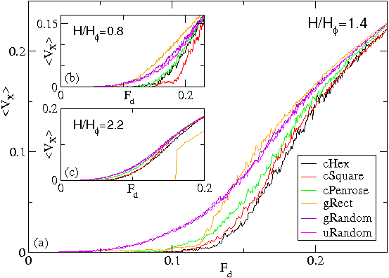
We first consider driving vortices along the gradient in the positive x-direction. We define the driving angle θ as the angle the driving direction makes with the positive x axis, so that θ = 0 corresponds to driving along the gradient direction. In Fig. 16(a) we plot 〈Vx 〉 versus Fd for systems with Fp = 0.55, θ = 0, and H/Hϕ = 1.4; we consider the cHex array shown in Fig. 4(b), the cSquare, cPenrose, gRect, and gRandom arrays shown in Fig. 15 and a uniform random array lacking any gradient. The depinning force Fc, defined as the magnitude of the drive above which 〈Vx 〉 ≥ 10−4, is significantly larger in the conformal arrays than in the non-conformal arrays. Additionally, in the moving phase the vortices travel more slowly through conformal arrays than through the nonconformal arrays over a substantial range of Fd. Among the conformal arrays, the cHex array gives the highest Fc, with Fc for the cSquare array almost as high and slightly smaller for the cPenrose array. At higher Fd the curves start to come together as the effectiveness of the pinning at the higher drives is washed out and 〈Vx 〉 ≈ Fd. At H/Hϕ=0.8, as shown in Fig. 16(b), 〈Vx〉 for the cSquare array drops below that of the cHex array at higher drives, indicating enhanced pinning effectiveness in the cSquare array, while the curves for the cHex and cPenrose arrays are very similar. The gRect array has the weakest pinning, followed by the random arrays with and without a gradient.
In Fig. 16(c) we illustrate the behavior at a higher field of H/Hϕ=2.2. At this field, the gRect array exhibits a highly enhanced depinning force, followed by an abrupt transition to steady vortex motion. Inspection of the vortex configurations reveals that the vortices form an ordered vortex chain state of the type discussed in Section VI, which locks them into place and prevents vortex flow. Because our gRect transport and magnetization arrays have somewhat different configurations, they form these ordered states at different field levels; however, the qualitative behavior of gRect remains the same during transport, with the array exhibiting enhanced performance only when it is able to form vortex chain states. The difference between the conformal and non-conformal random arrays is somewhat reduced at H/Hϕ=2.2, since it is above the cutoff field value of H/Hϕ=2.0 where the conformal arrays start to exhibit decreased pinning effectiveness. The conformal arrays still perform better by giving higher values of Fc and lower values of 〈Vx〉 in the moving phase than the random arrays. The cSquare and cHex arrays have almost the same behavior, and are again superior to cPenrose.
These results are completely consistent with the results from our magnetization simulations. The transport simulations confirm that the pinning effectiveness is enhanced in conformal arrays over non-conformal ones, and the fact that the gRandom and uRandom arrays give nearly identical results indicates that it is not merely the gradient in the pinning that matters but also the local ordering. The precise type of local ordering is of lesser importance, although (as with magnetization) the quasiperiodic Penrose ordering is somewhat less effective at enhancing the pinning than periodic orderings.

B.  Driving in different directions

Fig17.png
Figure 17: 〈Vx 〉 and 〈Vy 〉 vs Fd for current-driven systems with Fp = 0.55 at H/Hϕ = 1.4, driven at θ = 30° with respect to the positive x-axis. (a) cHex array; (b) gRandom array; (c) gRect array. The labeled current levels a-l correspond to the vortex trajectories illustrated in Fig. 18.
Fig18.png
Figure 18: Lines: vortex trajectories, dark dots: vortex positions, and light dots: pin positions for selected values of Fd in the current-driven systems described in Fig. 17 with Fp=0.55, H/Hϕ=1.4, and drive orientation θ = 30°. (a,b,c,d): cHex; (e,f,g,h): gRandom; (i,j,k,l): gRect. Fd= (a,e,i) 0.06, (b,f,j) 0.09, (c,g,k) 0.12, and (d,h,l) 0.14.
Next we consider the effect of changing θ, the orientation of the driving direction, for various gradient pinning arrays. In Fig. 17 we plot the average velocity in the x-direction 〈Vx 〉 and y-direction 〈Vy 〉 as a function of Fd for the cHex, gRandom, and gRect arrays, at a drive angle of θ = 30°. For the cHex array in Fig. 17(a), 〈Vy 〉 is nonzero for 0.05 < Fd < 0.10 while 〈Vx 〉 remains zero, meaning that vortex flow occurs strictly in the y-direction, perpendicular to the gradient, even though the largest component of the external drive is along the x direction. Once the vortices start to move along the x direction as well, we find a crossing of the 〈Vx〉 and 〈Vy〉 curves near Fd=0.15. In Fig. 18(a,b,c,d) we illustrate the vortex flow in the cHex array at the drive values marked with the letters a-d in Fig. 17(a). At Fd=0.06 and 0.09 in Figs. 18(a) and (b), the vortex flow occurs in winding rivers aligned with the y-direction, which pass through the portions of the sample in which the pinning density is lowest. The cHex array exhibits a pronounced guidance or channeling effect since most of the pins are occupied in the higher pinning density regions, creating a barrier to vortex motion, while the local depinning threshold is reduced in areas of lower pinning density. At Fd = 0.12, Fig. 18(c) shows that vortices begin to cross between the easy flow channels, passing through the denser pinning region. This corresponds with the emergence of a non-zero value of 〈Vx 〉 in Fig. 17(a) at point c. At higher drives the amount of motion in the x-direction between easy-flow channels increases, as illustrated in Fig. 18(d) at Fd = 0.14.
The depinning transition falls at a much lower value of Fd for the random gradient array, as shown in Fig. 17(b), and unlike in the cHex array there is no vortex guidance effect in which flow only occurs in the y-direction. Instead, 〈Vx〉 and 〈Vy〉 both increase smoothly with increasing Fd, and there is no crossing of the velocity curves. In Fig. 16 we showed that a random gradient array driven in the gradient direction with θ = 0° has essentially identical transport properties to a uniform random array, indicating that the addition of a gradient to a random array does not substantially affect vortex flow. Similarly, we find that for θ ≠ 0° the flow through random arrays is also not affected by the addition of a gradient. In Fig. 18(e,f,g,h) we show the vortex trajectories for the drives labeled e-h in Fig. 17. At Fd = 0.06 and 0.09 in Fig. 18(e) and (f), the vortices move in both the x and y directions and form winding channels oriented along the driving direction. Due to the less effective pinning in the gRandom array, the number of moving vortices is much greater than in the cHex array at the same drive, as can be seen by comparing the high trajectory densities in Fig. 18(e,f) to the much sparser trajectories in Fig. 18(a,b). At Fd = 0.14 in Fig. 18(h), most of the vortices are moving. At drives higher than those illustrated here, the vortices dynamically reorder in a manner similar to the dynamic reordering transitions observed for vortices driven over uniform random pinning arrays [64,65].
Figure 17(c) shows 〈Vx〉 and 〈Vy〉 versus Fd curves for the rectangular gradient array. Here there is a pronounced guidance effect for 0.02 < Fd < 0.11; however, unlike in the cHex array, 〈Vx 〉 is not strictly zero, indicating that some vortex motion is occurring in the x-direction between the 1D columns of pins since the gRect array is less effective in restricting vortex motion along its gradient. The vortex flow images in Fig. 18(i,j,k,l) correspond to the labeled drives in Fig.17(c). For Fd = 0.06 and 0.09 in Fig. 18(i) and (j), the vortices follow nearly 1D paths along the y direction with very little winding, while there are a smaller number of flow channels oriented approximately parallel to the x direction that connect some of the 1D paths. The 1D vertical flow channels are concentrated in the least dense portions of the pinning array, and are similar in nature to the 1D flow of interstitial vortices observed in uniform square or rectangular periodic pinning arrays [66]. At Fd = 0.12 in Fig. 18(k), there is a significant increase in the amount of vortex flow along the x-direction, while for Fd = 0.14 in Fig. 18(l) the flow is continuous though the system and oriented with the driving direction. As with the gRandom array, the high trajectory densities indicate pinning which is less effective than in the cHex array. For Fd > 0.20 the vortices dynamically order, as indicated by the onset of a linear regime of 〈Vx〉 versus Fd in Fig. 17(c).
Fig19.png
Figure 19: 〈Vx 〉 (circles) and 〈Vy 〉 (squares) vs drive angle θ for the cHex (a,c,e) and gRandom (b,d,f) arrays, at Fd = 0.09 (a,b), Fd = 0.14 (c,d), and Fd = 0.20 (e,f). We fix Fp = 0.55 and H/Hϕ = 1.4.
We summarize the transport properties for different drive angles in Fig. 19, where we plot 〈Vx 〉 and 〈Vy 〉 versus θ for different values of Fd in the cHex and gRandom arrays. In the absence of pinning, we would obtain 〈Vx 〉 = Fdcos(θ) and 〈Vy 〉 = Fdsin(θ). For the cHex array with Fd = 0.09, shown in Fig. 19(a), 〈Vx 〉 ≈ 0 for all θ, while 〈Vy 〉 monotonically increases with increasing θ. This drive is too weak to depin the vortices along the x-direction, but the vortices can flow in the y-direction through the low density regions as was shown in Fig. 18(b). Fig. 19(b) shows the same quantities for the gRandom array at the same drive Fd=0.09. Here 〈Vx 〉 is nonzero over the whole range of θ since the depinning threshold in the x-direction is much lower for the gRandom array. There is an asymmetry in the x and y direction responses, as indicated by the fact that 〈Vx 〉 = 0.015 at θ = 0° but 〈Vy 〉 = 0.021 at θ = 90°. This indicates that the pinning in the moving phase is slightly more effective when the vortices are moving along the gradient direction. However, the vortex velocities are much larger in the gRandom array than in the cHex array over the whole range of θ, showing the robust enhanced effectiveness of the conformal pinning.
When the drive in the cHex array is increased to Fd = 0.14, Fig. 19(c) shows that the x-direction depinning threshold is exceeded for θ < 70°, but that the vortex motion along the x direction is still greatly suppressed even when the vortices are flowing. There is still a strong vortex channeling effect in the y-direction, as reflected in the large asymmetry between 〈Vx 〉(θ) and 〈Vy 〉(90°−θ). For the gRandom array at Fd=0.14, Fig. 19(d) indicates that this drive magnitude is already large enough to render the pinning mostly ineffective, as also shown in Fig. 18(h). The 〈Vx 〉 and 〈Vy 〉 curves are almost mirror-symmetric, indicating that the pinning gradient has little effect on the motion of the vortices. At Fd = 0.20, Fig. 19(e) shows that the response of cHex becomes increasingly symmetrical, although there is still a small channeling regime for θ ≥ 80° where the flow is strictly confined along the y-direction. At higher drives (not shown), the 〈Vx 〉 and 〈Vy 〉 curves for cHex become symmetric. For the gRandom array at Fd=0.20, Fig. 19(f) indicates that the response is almost completely symmetrical.

VIII.  SUMMARY

We have investigated the magnetization, ordering, and transport for vortices interacting with pinning arrays where there is a gradient in the pinning density. We consider conformal pinning arrays constructed by taking a conformal transformation of a uniform pinning array; the new structure has a density gradient but preserves certain crystalline topological features of the original lattice. In particular, we examine conformal crystals obtained from uniform hexagonal, square, Archimedean and quasiperiodic arrays. We also investigate selected non-conformal arrays with a pinning gradient, including a rectangular pinning array with a 1D gradient and a random arrangement of pinning sites with a gradient. In general we find that conformal arrays which are transformed versions of uniform pinning with well-defined commensurability peaks give the strongest pinning over the widest range of fields. The hexagonal and square conformal arrays produce the strongest pinning and highest critical currents, followed by the conformal Archimedean and conformal Penrose arrays. The random gradient array gives only a slight enhancement in pinning over a uniform random array, indicating that it is the preservation of the local periodicity in the conformal transformation combined with the gradient that gives rise to the enhanced pinning. We show that for the conformal crystal arrays, a portion of the vortices in the sample is locally commensurate with a portion of the pinning array, and this local commensuration effect gradually moves through the system as the externally applied magnetic field is changed. When the field becomes high enough that the vortex density exceeds the pinning density at the outer edge of the sample, the effectiveness of the conformal arrays breaks down, although they still show a small enhancement in pinning compared to random arrays. The rectangular gradient pinning array has relatively weak pinning compared to the conformal arrays at lower fields; however, for higher fields, it develops a pronounced broad peak due to a novel commensuration effect in which integer numbers of ordered columns of vortices fit between the columns of pinning sites.
We also show that the enhanced pinning by the conformal arrays can be observed in current-driven transport measurements. Compared to uniform random or random gradient arrays, the conformal arrays have higher critical depinning forces, and lower average vortex velocities in the moving phase. When the vortices are driven at different angles with respect to the gradient direction, the conformal arrays guide vortex flow perpendicular to the gradient, in channels that pass through the regions of lower pinning density. The rectangular gradient array exhibits a similar guidance effect, with a strongly 1D flow of vortices in the interstitial regions.
In this work we focus on vortices in gradient arrays; however, we expect similar results for other systems featuring particles moving over substrates where the substrate has some type of gradient.

ACKNOWLEDGMENTS

We thank Boldizsár Jankó for useful discussions. This work was carried out under the auspices of the NNSA of the U.S. DoE at LANL under Contract No. DE-AC52-06NA25396.

References

[1]
G. Blatter, M.V. Feigel'man, V.B. Geshkenbein, A.I. Larkin, and V.M. Vinokur, Rev. Mod. Phys. 66, 1125 (1994).
[2]
G. Grüner, Rev. Mod. Phys. 60, 1129 (1988).
[3]
V. J. Goldman, M. Santos, M. Shayegan, and J.E. Cunningham, Phys. Rev. Lett. 65, 2189 (1990); G. A. Csáthy, D. C. Tsui, L. N. Pfeiffer, and K. W. West, Phys. Rev. Lett. 98, 066805 (2007).
[4]
A. Vanossi, N. Manini, M. Urbakh, S. Zapperi, and E. Tosatti, Rev. Mod. Phys. 85, 529 (2013).
[5]
S. Xia, L. Ponson, G. Ravichandran, and K. Bhattacharya, Phys. Rev. Lett. 108, 196101 (2012).
[6]
D. Ravelosona, D. Lacour, J. A. Katine, B. D. Terris, and C. Chappert, Phys. Rev. Lett. 95, 117203 (2005).
[7]
A. Vanossi, N. Manini, and E. Tosatti, Proc. Natl. Acad. Sci. USA 109, 16429 (2012); D. McDermott, J. Amelang, C. J. Olson Reichhardt, and C. Reichhardt, Phys. Rev. E 88, 062301 (2013).
[8]
M. Baert, V. V. Metlushko, R. Jonckheere, V. V. Moshchalkov, and Y. Bruynseraede, Phys. Rev. Lett. 74, 3269 (1995).
[9]
K. Harada, O. Kamimura, H. Kasai, T. Matsuda, A. Tonomura, and V. V. Moshchalkov, Science 274, 1167 (1996).
[10]
S. Goldberg, Y. Segev, Y. Myasoedov, I. Gutman, N. Avraham, M. Rappaport, E. Zeldov, T. Tamegai, C.W. Hicks, and K.A. Moler, Phys. Rev. B 79, 064523 (2009).
[11]
I. Swiecicki, C. Ulysse, T. Wolf, R. Bernard, N. Bergeal, J. Briatico, G. Faini, J. Lesueur, and J. E. Villegas, Phys. Rev. B 85, 224502 (2012); R. Cordoba et al, Nature Communications 4, 1437 (2013).
[12]
J. I. Martín, M. Velez, J. Nogues, and I. K. Schuller, Phys. Rev. Lett. 79, 1929 (1997); C. Chiliotte, G. Pasquini, V. Bekeris, J. E. Villegas, C.-P. Li, and I. K. Schuller, Supercond. Sci. Technol. 24, 065008 (2011).
[13]
U. Welp, X. L. Xiao, V. Novosad, and V. K. Vlasko-Vlasov, Phys. Rev. B 71, 014505 (2005).
[14]
C. J. Olson, C. Reichhardt, and F. Nori, Phys. Rev. B 56, 6175 (1997).
[15]
C. Reichhardt, C. J. Olson, and F. Nori, Phys. Rev. B 57, 7937 (1998).
[16]
C. Reichhardt, G. T. Zimányi, R. T. Scalettar, A. Hoffmann, and I. K. Schuller, Phys. Rev. B 64, 052503 (2001).
[17]
G. R. Berdiyorov, M. V. Milosevic, and F. M. Peeters, Phys. Rev. Lett. 96, 207001 (2006); Phys. Rev. B 74, 174512 (2006).
[18]
C. Reichhardt and N. Grønbech-Jensen, Phys. Rev. B 63, 054510 (2001).
[19]
S. B. Field, S. S. James, J. Barentine, V. Metlushko, G. Crabtree, H. Shtrikman, B. Ilic, and S. R. J. Brueck, Phys. Rev. Lett. 88, 067003 (2002); A. N. Grigorenko, S. J. Bending, M. J. Van Bael, M. Lange, V. V. Moshchalkov, H. Fangohr, and P. A. J. de Groot, Phys. Rev. Lett. 90, 237001 (2003).
[20]
J. I. Martín, M. Vélez, A. Hoffmann, I. K. Schuller, and J. L. Vicent, Phys. Rev. Lett. 83, 1022 (1999); Ajay D. Thakur, S. Ooi, M. Chand, J. Jesudasan, P. Raychaudhuri, and K. Hirata, AIP Conf. Proc. 1591, 1651 (2014).
[21]
M. Vélez, J.I. Martín, J.E. Villegas, A. Hoffmann, E.M. González, J.L. Vicent, and I. K. Schuller, J. Mag. Mag. Mat. 320, 2547 (2008).
[22]
C. Reichhardt, G. T. Zimányi, and N. Grønbech-Jensen, Phys. Rev. B 64, 014501 (2001).
[23]
G. Karapetrov, J. Fedor, M. Iavarone, D. Rosenmann, and W. K. Kwok, Phys. Rev. Lett. 95, 167002 (2005).
[24]
C. J. Olson Reichhardt, A. Libál, and C. Reichhardt, Phys. Rev. B 73, 184519 (2006).
[25]
T. C. Wu, J. C. Wang, Lance Horng, J. C. Wu, and T. J. Yang, J. Appl. Phys. 97, 10B102 (2005).
[26]
C. Reichhardt and C. J. Olson Reichhardt, Phys. Rev. B 76, 064523 (2007).
[27]
C. Reichhardt and C. J. Olson Reichhardt, Phys. Rev. Lett. 100, 167002 (2008).
[28]
M. L. Latimer, G. R. Berdiyorov, Z. L. Xiao, W. K. Kwok, and F. M. Peeters, Phys. Rev. B 85, 012505 (2012).
[29]
C. Reichhardt and C. J. Olson Reichhardt, Phys. Rev. B 76, 094512 (2007).
[30]
M. Kemmler, D. Bothner, K. Ilin, M. Siegel, R. Kleiner, and D. Koelle, Phys. Rev. B 79, 184509 (2009).
[31]
Y. J. Rosen, A. Sharoni, and I. K. Schuller, Phys. Rev. B 82, 014509 (2010).
[32]
C. J. Olson Reichhardt and C. Reichhardt, Phys. Rev. B 81, 224516 (2010).
[33]
N. S. Lin, T. W. Heitmann, K. Yu, B. L. T. Plourde, and V. R. Misko, Phys. Rev. B 84, 144511 (2011).
[34]
G. Karapetrov, V. Yefremenko, G. Mihajlovic, J. E. Pearson, M. Iavarone, V. Novosad, and S. D. Bader, Phys. Rev. B 86, 054524 (2012).
[35]
K. Yu, M. B. S. Hesselberth, P. H. Kes, and B. L. T. Plourde, Phys. Rev. B 81, 184503 (2010).
[36]
A. Libál, C. J. Olson Reichhardt, and C. Reichhardt, Phys. Rev. Lett. 102, 237004 (2009).
[37]
M. L. Latimer, G. R. Berdiyorov, Z. L. Xiao, F. M. Peeters, and W. K. Kwok, Phys. Rev. Lett. 111, 067001 (2013).
[38]
J. Trastoy, M. Malnou, C. Ulysse, R. Bernard, N. Bergeal, G. Faini, J. Lesueur, J. Briatico, and J. E. Villegas, arXiv:1307.2881.
[39]
A. V. Silhanek, L. Van Look, R. Jonckheere, B. Y. Zhu, S. Raedts, and V. V. Moshchalkov, Phys. Rev. B 72, 014507 (2005).
[40]
R. Cao, Lance Horng, T. J. Yang, T. C. Wu, J. C. Wang, and J. C. Wu, J. of Appl. Phys. 107, 09E129 (2010).
[41]
A. Kiliç, K. Kiliç, M. Oluta s, and A. Altinkok, Eur. Phys. J. B 86, 339 (2013).
[42]
V. R. Misko, S. Savel'ev, and F. Nori, Phys. Rev. Lett. 95, 177007 (2005); Phys. Rev. B 74, 024522 (2006).
[43]
A. V. Silhanek, W. Gillijns, V. V. Moshchalkov, B. Y. Zhu, J. Moonens, and L. H. A. Leunissen, Appl. Phys. Lett. 89, 152507 (2006).
[44]
J. E. Villegas, M. I. Montero, C.-P. Li, and I. K. Schuller, Phys. Rev. Lett. 97, 027002 (2006).
[45]
M. Kemmler, C. Gurlich, A. Sterck, H. Pöhler, M. Neuhaus, M. Siegel, R. Kleiner, and D. Koelle, Phys. Rev. Lett. 97, 147003 (2006).
[46]
R. B. G. Kramer, A. V. Silhanek, J. Van de Vondel, B. Raes, and V. V. Moshchalkov, Phys. Rev. Lett. 103, 067007 (2009).
[47]
V. R. Misko, D. Bothner, M. Kemmler, R. Kleiner, D. Koelle, F. M. Peeters, and F. Nori, Phys. Rev. B 82, 184512 (2010).
[48]
C. Reichhardt and C. J. Olson Reichhardt, Phys. Rev. Lett. 106, 060603 (2011).
[49]
D. Ray, C. J. Olson Reichhardt, B. Jankó, and C. Reichhardt, Phys. Rev. Lett. 110, 267001 (2013).
[50]
P. Pieranski, in Phase Transitions in Soft Condensed Matter, edited by T. Riste and D. Sherrington (Plenum, New York, 1989), p. 45; F. Rothen, P. Pieranski, N. Rivier, and A. Joyet, Eur. J. Phys. 14, 227 (1993); F. Rothen and P. Pieranski, Phys. Rev. E 53, 2828 (1996).
[51]
D. Ray, C. Reichhardt, C. J. Olson Reichhardt, and B. Jankó, Physica C 503, 123 (2014) .
[52]
Y. L. Wang, M. L. Latimer, Z. L. Xiao, R. Divan, L. E. Ocola, G. W. Crabtree, and W. K. Kwok, Phys. Rev. B 87, 220501(R) (2013).
[53]
S. Guénon, Y. J. Rosen, A. C. Basaran, and I. K. Schuller, Appl. Phys. Lett. 102, 252602 (2013).
[54]
M. Motta, F. Colauto, W. A. Ortiz, J. Fritzsche, J. Cuppens, W. Gillijns, V. V. Moshchalkov, T. H. Johansen, A. Sanchez, and A. V. Silhanek, Appl. Phys. Lett. 102, 212601 (2013).
[55]
V. R. Misko and F. Nori, Phys. Rev. B 85, 184506 (2012).
[56]
D. Ray, C. Reichhardt, and C.J. Olson Reichhardt, Supercond. Sci. Technol. 27, 075006 (2014).
[57]
B. Grünbaum and G.C. Shephard, Tilings and Patterns (W.H. Freeman, New York, 1987).
[58]
See, for example, Z. Nehari, Conformal Mapping. (Dover, New York, 1975 [1952]).
[59]
See, for example, J.-B. Suck, M. Schrieber, and P. Häussler (eds.), Quasicrystals: An Introduction to Structure, Physical Properties, and Applications (Springer, Berlin, 2002).
[60]
C. Reichhardt, C. J. Olson, J. Groth, S. Field, and F. Nori, Phys. Rev. B 52, 10441 (1995); Phys. Rev. B 53, R8898(R) (1996).
[61]
C. Reichhardt, J. Groth, C. J. Olson, S. B. Field, and F. Nori, Phys. Rev. B 54, 16108 (1996).
[62]
C.P. Bean, Phys. Rev. Lett. 8, 250 (1962); Rev. Mod. Phys. 36, 31 (1964).
[63]
C. Reichhardt, C. J. Olson, and F. Nori, Phys. Rev. Lett. 78, 2648 (1997).
[64]
A. E. Koshelev and V. M. Vinokur, Phys. Rev. Lett. 73, 3580 (1994); M. C. Faleski, M. C. Marchetti, and A. A. Middleton, Phys. Rev. B 54, 12427 (1996).
[65]
C. J. Olson, C. Reichhardt, and F. Nori, Phys. Rev. Lett. 81, 3757 (1998).
[66]
C. Reichhardt and C. J. Olson Reichhardt, Phys. Rev. B 79, 134501 (2009); J. Gutierrez, A. V. Silhanek, J. Van de Vondel, W. Gillijns, and V. V. Moshchalkov, Phys. Rev. B 80, 140514 (2009).


File translated from TEX by TTHgold, version 4.00.
Back to Home