Physical Review Letters 102, 237004 (2009)

Creating Artificial Ice States Using Vortices in Nanostructured Superconductors

A. Libál, C.J. Olson Reichhardt, and C. Reichhardt
Theoretical Division, Los Alamos National Laboratory, Los Alamos, New Mexico 87545, USA

(Received 27 August 2008; published 12 June 2009)

We demonstrate that it is possible to realize vortex ice states that are analogous to square and kagome ice. With numerical simulations, we show that the system can be brought into a state that obeys either global or local ice rules by applying an external current according to an annealing protocol. We explore the breakdown of the ice rules due to disorder in the nanostructure array and show that in square ice, topological defects appear along grain boundaries, while in kagome ice, individual defects appear. We argue that the vortex system offers significant advantages over other artificial ice systems.

DOI: 10.1103/PhysRevLett.102.237004
PACS numbers: 74.25.Qt, 75.10.Nr


Square Ice
Kagome Ice
References


Geometric frustration occurs when a system is constrained by geometry in such a way that the pairwise interaction energy cannot be simultaneously minimized for all constituents, and appears in water ice [1], spin systems [2,3,4], and a variety of other systems in both physics [5] and biology [6]. A specific example of frustration occurs in the classical spin ice system where the constituents of the system are magnetic spins on a grid of corner-sharing tetrahedra. The spins are constrained to point along the lines connecting the middle points of the tetrahedra [3,4] and pairs of spins can minimize their energy by adopting a head-to-tail configuration. It is not, however, possible for the four spins on a tetrahedron to simultaneously satisfy each of the six pairwise interactions in a head-to-tail fashion; the best the system can do is to satisfy four interactions out of six, leaving two pairs in a head-to-head or tail-to-tail configuration. As a result, in the ground state configuration each tetrahedron obeys the so-called "ice rule" of a two-in two-out configuration with two spins pointing toward the center of the tetrahedron and two spins pointing away from it. Defects appear in the form of magnetic monopoles [7].
Recently, there has been growing interest in creating model systems that exhibit spin-ice behavior [8,9,10,11,12,13,14] and that allow the individual constituents to be imaged directly, unlike molecular or atomic ices. For example, Wang et al. [8] created artificial square ice using single-domain rectangular ferromagnetic islands arranged in a square lattice such that four islands meet at every vertex point. They found that as the inter-island interaction increased, the system preferentially formed ice-rule-obeying vertices, but it did not reproduce the known ground state of two-dimensional (2D) spin ice, where the two "in" magnetic moments are on opposite sides of the vertex. This could be due to the relative weakness of the magnetic interactions. It has recently been shown that certain dynamical annealing protocols permit the system to approach the ground state more closely [9,10]. Similar studies have been performed for a 2D kagome ice system [12,13] where the local ice-rules were obeyed and defects such as three-in or three-out were absent [13]. In the colloidal artificial ice system of Ref. [14], the local dynamics can be accessed easily via video microscopy; however, the ice arrays in this system are limited to relatively small sizes in experiment.
Here we propose that a particularly promising artificial ice system could be created using vortices in superconductors with appropriately designed nanostructured arrays of artificial pinning sites. There has been extensive experimental work showing that a rich variety of different pinning array geometries can be fabricated [15,16,17,18,19,20], and various types of experimental techniques exist for directly imaging vortices in these arrays [17,18,19,21]. The vortex system has several advantages over other artificial ice systems. The vortex-vortex interaction strength is large, permitting the ground state to be reached much more readily than in the nanomagnetic systems. An applied external current permits the straightforward realization of different dynamical annealing protocols. New types of defects can be studied by merely increasing or decreasing the magnetic field to create vacancies or interstitials that locally break the ice rules, while transport properties and critical currents can be measured which are not accessible in the other systems.
To form square vortex ice, we propose using an arrangement of elongated double-well pinning sites. Nonsuperconducting islands with the double-hump shape illustrated in Fig. 1(a) placed within a superconducting layer have a pair of potential minima at the highest points of the island where the superconducting layer is the shallowest. A single vortex trapped over each island will sit at one of the two minima, depending on the interactions with nearby vortices. By changing the arrangement of the islands, different types of ice can be created. For square ice, shown in Fig. 1(a), four islands come together at each vertex and the state of each island is defined as "in" if the vortex sits close to the vertex and "out" otherwise. We define nin as the number of "in" vortices at a vertex. In Fig. 1(a), the vortices have formed an nin=2 ice-rule-obeying ground state configuration. Figure 1(b) shows a kagome spin ice arrangement with three islands surrounding each vertex. In this case, the lowest energy state has nin=1 or nin=2 at each vertex, but there is no overall ordering into a unique ground state.
Fig1.png
Figure 1: Schematic of the nanostructured pinning site configurations producing ice states. Double-lobed objects: pins; open mesh objects: vortices. a) Square ice ground state. b) One possible biased ground state of the kagome ice system.
To study the vortex ice, we perform numerical simulations of a 2D sample with periodic boundaries containing Np elongated pinning sites in the square or kagome configurations illustrated in Fig. 1 and Nv=Np vortices. A vortex i at position Ri obeys the following overdamped equation of motion: η(dRi/dt) = fivv + fsi + fd + fTi. The damping constant η = ϕ02d/2πξ2ρN, where ϕ0=h/2e is the flux quantum, ξ is the superconducting coherence length, ρN is the normal state resistivity of the material, and d is the thickness of the superconducting crystal. The vortex-vortex interaction force is given by fivv = ∑Nvjif0K1(Rij/λ)Rij, where K1 is the modified Bessel function appropriate for stiff three-dimensional vortex lines, λ is the London penetration depth, f002/(2πμ0λ3), Rij=|RiRj|, and Rij=(RiRj )/Rij. The substrate force fsi arises from the elongated pins, fsik = ∑kNpf0(fp/rp)Rik± Θ(rpRik±)Rik±+f0(fp/rp)Rik Θ(rpRik)Rik+f0(fb/l)(1−Rik||) Θ(lRik||)Rik||. Here Rik±=|RiRkp ±lpk|||, Rik⊥,|| = |(RiRkp) ·pk⊥,|||, Rkp is the position of pin k, and pk|| (pk) is a unit vector parallel (perpendicular) to the axis of pin k. Each vortex is constrained to stay within a pin composed of two half-parabolic wells of radius rp=0.4λ separated by an elongated region of length 2l which confines the vortex perpendicular to the pin axis and has a repulsive potential or barrier of strength fb parallel to the axis which pushes the vortex out of the middle of the pin into one of the ends. We take l=2/3λ or 5/6λ and vary the lattice constant a of the pinning array between a=2.0λ and 8.0λ. The driving force fd represents the Lorentz force from an applied current. The thermal force fTi comes from thermal Langevin kicks and is set to zero except during the annealing of the kagome ice.
Square Ice - We prepare the square ice system using a dynamical annealing procedure inspired by the nanomagnetic ice results of Refs. [9,10]. In our simulations, we place one vortex in each pin at a random position and then use a protocol of a rotating in-plane applied current with decreasing amplitude, fd = Aac(t)(cos(2πt/Tr)x + sin(2πt/Tr)y), where Tr=1000 simulation time steps, Aac(t)=±(A0−δAtt⎦), A0=2.0f0, δt=10000 simulation time steps, and δA=0.01f0. The force direction is reversed each time the magnitude of the force is decreased. We measure the number of vertices of each type that appear after completing the dynamical annealing. For the kagome ice system, we obtain the vortex configurations from standard thermal simulated annealing.
To determine how effectively the dynamical annealing protocol brings the square ice system to the ground state, we introduce disorder to the system by replacing the delta-function distributed barriers fb at the center of each pinning site with barriers of normally distributed strength, where the mean strength is fb and the width of the distribution is σ. In Fig. 2, we illustrate the vertices that have reached the ground state configuration of nin=2 in a square ice sample with a=2.5λ, l=5/6λ and fb=0.25f0 for differing disorder widths σ. The dots represent vertices in the ice-rule obeying ground state, while the closed black circles indicate higher energy vertices that we term ice-rule defects DI since they still obey the nin=2 ice rule but have the two "in" vortices adjacent to one another. The open circles mark the highest energy vertices that we term non-ice-rule defects DNI since they do not obey the nin=2 ice rule but have, for example, nin=3 or nin=0. For σ < 0.1, the system can reach the ordered ground state as shown in Fig. 2(a). As the central barriers of the pins become more nonuniform with increasing σ, some pinning centers act as nucleation sites for grain boundaries, as illustrated in Figs. 2(b) and 2(c) for σ = 0.1 and σ = 0.5. In general, we find that for 0.1 < σ < 0.7, all of the defected vertices form closed loop grain boundaries and the ratio of DI to DNI is 1:1 due to geometric constraints. For σ ≥ 0.7, Fig. 2(d) shows that a proliferation of DNI occurs so that the DNI outnumber the DI. The grain boundary loops interact and wind around the sample, making it difficult to determine the relation between σ and the grain boundary length. We find that individual DNI can appear outside of grain boundaries, while DI always remain confined to grain boundaries, suggesting that there could be a disorder-induced phase transition when the DNI proliferate. We also find that doubly occupied pinning sites with two vortices each can act as grain boundary nucleation sites, as illustrated in the inset of Fig. 3(b).
Fig2.png
Figure 2: Grain boundary images in square ice samples with a=2.5λ, l=5/6λ, and fb=0.25 for increasing disorder width σ. Dots: ground state nin=2 ice-rule obeying vertices; filled black circles: ice-rule defects DI; white circles: non-ice-rule defects DNI. (a) σ = 0. (b) σ = 0.1. (c) σ = 0.5. (d) σ = 1.0.
In Fig. 4(a), we plot the percentage of vertices PGS that are in the ice-rule-obeying ground state as a function of time during the dynamical annealing procedure in a sample with a=2.5λ, l=5/6λ, fb=0.25f0, and different values of σ. At early times, when |Aac| is close to A0, all of the vortices follow the drive and switch back and forth inside the pinning sites. As |Aac| decreases, a transition occurs when the vortices cease to follow the driving direction and become locked into one position in the pinning site. For σ = 0, this locking transition is relatively sharp and occurs at |Aac| ≈ 0.82f0. Nonzero values of σ broaden the transition significantly and cause some vertices to lock into the ground state at much earlier times; at the same time, complete locking of all vertices into the ground state can no longer be achieved within the finite time of the dynamical annealing process. We quantify the broadening of the transition with increasing σ by fitting the curves in Fig. 4(a) to the form PGS(t)=1−exp(t/τ). Figure 4(b) shows the fitted relaxation time τ as a function of σ and indicates the occurrence of an increasingly slow locking process as the disorder width increases. The dependence of PGS on both a and σ is summarized in Fig. 4(d) for a system with fb=1.0 and l=2/3λ. Here, PGS decreases both with increasing σ and with increasing a as the relative strength of the vortex-vortex interactions decreases.
Depending on the system parameters, it is not always necessary to perform a dynamical annealing procedure in order to reach the ground state. To demonstrate this, we prepare the sample in a random state and then apply a fixed amplitude rotating drive, fd=~A(cos(2πt/Tr)x+sin(2πt/Tr)y), with ~A=0.01f0 and Tr=1000 simulation time steps, for 2×10⁶ simulation time steps. When the central barrier in the pin fb is weak, the system can reach the ordered ground state under the weak external shaking. For larger fb, the system cannot reach the ordered ground state without dynamical annealing. This is shown in Fig. 4(c), where we plot the final PGS at the end of the simulation time versus fb for samples with σ = 0.01 and varied pinning lattice constant a=2.0λ, 2.5λ, and 3.0λ. For large fb, the sample is immediately frozen into the disordered initial configuration, and PGS ≈ 0.125, consistent with the value expected in a completely random sample. As fb is lowered, a spontaneous rearrangement into a partially ordered state becomes possible and PGS > 0.125. The value of fb at which the spontaneous ordering appears increases with decreasing a, indicating that as the vortex-vortex interactions grow stronger in the denser pinning arrays, the ordered ground state is much more energetically favored.
Fig3.png
Figure 3: (a) Ordered biased ground state in a sample with kagome pinning, fb=1.0, l=2/3λ, and a=3λ. Open circles: nin=1 vertices; shaded circles: nin=2 vertices. (b) Percentage PV of each vertex type vs a. Crosses: nin=0; open circles: nin=1; shaded circles: nin=2; filled squares: nin=3. Inset: grain boundary image in square ice sample with two doubly occupied pins (open squares) with the same symbols as in Fig. 2. (c) Vertex configuration after thermal annealing in a sample with a=3.5λ, l=2/3, and fb=1.0. Symbols are the same as in the main panel of (b).
Fig4.png
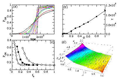
Figure 4: (a) Percentage PGS of ice-rule obeying ground state vertices vs time during the dynamical annealing process for different disorder widths σ. From upper right to lower right, σ = 0, 0.01, 0.05, 0.1, 0.2, 0.3, 0.4, 0.5, 0.6, 0.8, and 1.0. Here, a=2.5λ, l=5/6λ, and fb=0.25. (b) Relaxation time τ vs σ for the same system. (c) Final value of PGS vs fb in samples subjected to a small shaking field with no dynamical annealing. Here l=5/6λ, σ = 0.1, and a=2.0λ (open circles), 2.5λ (filled squares), and 3.0λ (open diamonds). (d) PGS vs σ and a in a sample with fb=1.0 and l=2/3λ.
Kagome Ice - The kagome lattice illustrated in Fig. 1(b) has a distinct set of ice rules from the square lattice. High energy vertices with nin=0 or 3 are avoided in favor of the kagome-ice-rule obeying vertices with nin=1 or 2. This system can form a nonunique ordered ground state, but only in the presence of an external biasing field. In Fig. 3(a) we show one possible biased ordered ground state for a kagome lattice with fb=1.0 and σ = 0 obtained by applying a constant drive fd=0.01f0(x+y) along a lattice symmetry direction while performing simulated annealing. In the absence of the biasing force, some high energy defect vertices which take the form of monopoles appear in the system and there is no overall order, as illustrated in Fig. 3(c). We find that the kagome ice is more robust against the effects of disorder than the square ice, in agreement with experimental findings for nanomagnetic kagome ice [13]. The defect patterns are distinct from the square ice since no grain boundary state forms for the kagome ice due to the lack of an ordered ground state. Unlike the bipartite square lattice, the nonbipartite kagome lattice is not topologically constrained, making our system more closely resemble the ice state studied in Ref. [22] than that considered in Ref. [23]. Although Fig. 3(c) shows that there is some tendency for the defected vertices to form pairs, there are no extended defect patterns of the type seen in Fig. 2. Since the ice rules in this system are enforced by the vortex-vortex interaction energies, we can weaken the enforcement of the ice rules by increasing the spacing a between pinning sites. Figure 3(b) shows that as a increases, the system passes from a limit in which only kagome-ice-rule obeying vortices appear for a ≤ 4λ to a limit a ≥ 8λ where the vertices assume a completely random arrangement. In the random limit, we expect to find each of the two defect vertex types with probability 1/8 and each of the two kagome-ice-rule obeying vertices with probability 3/8.
There are other arrays that would obey ice-rule type constraints; however, the simplest cases for 2D are the square and kagome arrays. Previous studies of superconducting wire networks arranged in kagome configurations found geometrical frustration which produced disordered ground states [24]; however, such a system does not specifically have ice-rule obeying states. The artificial ice vortex system proposed here can be used to study the effect of ice-rule and non-ice-rule configurations on transport and magnetization properties, and it would also be possible to examine higher matching fields to see whether new types of ordered or disordered states appear.
In summary, we propose that square and kagome vortex ice can be realized in nanostructured superconductors. By using an annealing protocol of a rotating externally applied current, the system can reach or approach the square ice ground state. In the presence of quenched disorder, defects appear in an ordered ground state background. For moderate disorder in the square ice system, all of the defects are bound to grain boundaries, while for strong disorder, individual high energy vertices proliferate. For kagome ice, we find no grain boundary phase in the presence of disorder. We predict that if the barrier for vortex motion across the center of each artificial pinning site is weak, the system will spontaneously organize into a partially ordered state even without use of an annealing protocol. This system could have interesting transport and memory effects which may manifest themselves as changes in the critical current, an effect which cannot be accessed readily in other artificial ice systems.
We thank C. Nisoli for a useful discussion. This work was carried out under the NNSA of the U.S. DoE at LANL under Contract No. DE-AC52-06NA25396.

References

[1]
L. Pauling, J. Am. Chem. Soc. 57, 2680 (1935).
[2]
P.W. Anderson, Phys. Rev. 102, 1008 (1956).
[3]
R. Moessner and A.P. Ramirez, Phys. Today, 59(2), 24 (2006).
[4]
A.P. Ramirez et al., Nature (London) 399, 333 (1999).
[5]
Y. Han et al., Nature (London) 456, 898 (2008).
[6]
H. Frauenfelder, P.G. Wolynes, and R.H. Austin, Rev. Mod. Phys. 71, S419 (1999); H.M. Harreis, C.N. Likos, and H. Löwen, Biophys. J. 84, 3607 (2003).
[7]
C. Castelnovo, R. Moessner, and S.L. Sondhi, Nature 451, 42 (2008); L.A.S. Mol et al., arXiv:0809.2105.
[8]
R.F. Wang et al., Nature (London) 439, 303 (2006).
[9]
C. Nisoli et al., Phys. Rev. Lett. 98, 217203 (2007).
[10]
X. Ke et al., Phys. Rev. Lett. 101, 037205 (2008).
[11]
G. Möller and R. Moessner, Phys. Rev. Lett. 96, 237202 (2006).
[12]
M. Tanaka et al., Phys. Rev. B 73, 052411 (2006).
[13]
Y. Qi, T. Brintlinger, and J. Cumings, Phys. Rev. B 77, 094418 (2008).
[14]
A. Libál, C. Reichhardt, and C.J. Olson Reichhardt, Phys. Rev. Lett. 97, 228302 (2006).
[15]
M. Baert et al., Phys. Rev. Lett. 74, 3269 (1995).
[16]
J.I. Martín et al., Phys. Rev. Lett. 83, 1022 (1999).
[17]
K. Harada et al., Science 274, 1167 (1996).
[18]
S.B. Field et al., Phys. Rev. Lett. 88, 067003 (2002); A.N. Grigorenko et al., ibid. 90, 237001 (2003).
[19]
G. Karapetrov et al., Phys. Rev. Lett.  95, 167002 (2005).
[20]
G. Karapetrov et al, Appl. Phys. Lett. 87, 162515 (2005).
[21]
I.V. Grigorieva et al., Phys. Rev. Lett. 99, 147003 (2007).
[22]
A.S. Wills, R. Ballou, and C. Lacroix, Phys. Rev. B 66, 144407 (2002).
[23]
R. Moessner and S.L. Sondhi, Phys. Rev. B 68, 064411 (2003); S.V. Isakov, R. Moessner, and S.L. Sondhi, Phys. Rev. Lett. 95, 217201 (2005).
[24]
M.S. Rzchowski, Phys. Rev. B 55, 11745 (1997); D. Davidovic et al., ibid. 55, 6518 (1997); K. Park and D.A. Huse, ibid. 64, 134522 (2001); M.J. Higgins et al., ibid. 61, R894 (2000); Y. Xiao et al., ibid. 65, 214503 (2002).


File translated from TEX by TTHgold, version 4.00.
Back to Home