 Figure 14:
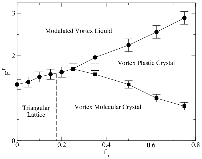
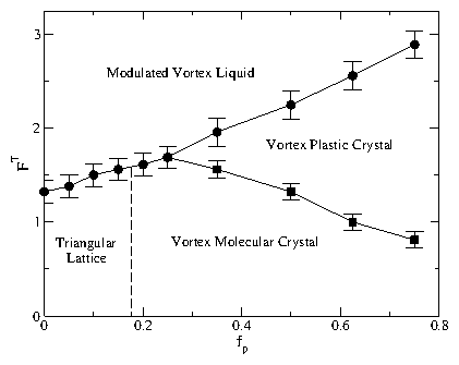
The temperature FT vs pinning strength fp phase diagram for the honeycomb pinning
array at B/BHϕ = 2.0 in the dimer state.
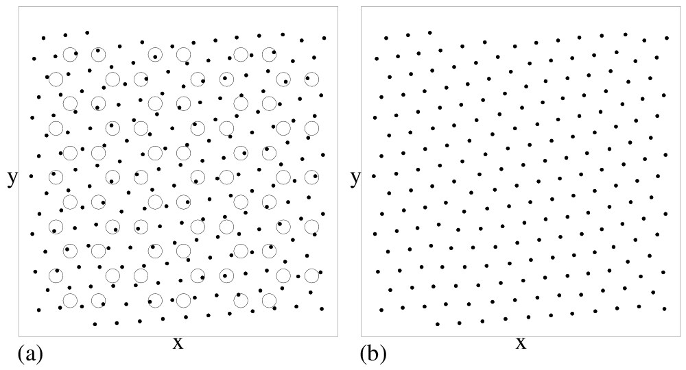
The four phases include: the vortex molecular crystal phase
illustrated in Fig. 5(a,b),
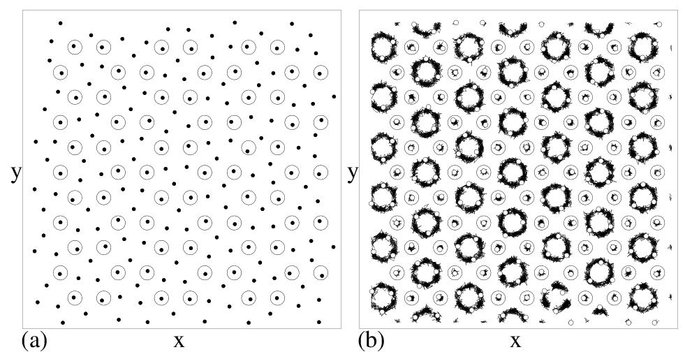
a vortex plastic crystal phase shown
in Fig. 13(a,b),
a modulated vortex liquid phase where motion occurs throughout
the sample, and a partially pinned triangular vortex lattice
that forms at low fp and low temperature which is described
in Fig. 15.
Circles: Onset of significant diffusion as determined from the
diffusion measurement D.
Squares: Loss of orientational order as determined from
P, the fraction of orientationally ordered
dimers.
Figure 14:
The temperature FT vs pinning strength fp phase diagram for the honeycomb pinning
array at B/BHϕ = 2.0 in the dimer state.
The four phases include: the vortex molecular crystal phase
illustrated in Fig. 5(a,b),
a vortex plastic crystal phase shown
in Fig. 13(a,b),
a modulated vortex liquid phase where motion occurs throughout
the sample, and a partially pinned triangular vortex lattice
that forms at low fp and low temperature which is described
in Fig. 15.
Circles: Onset of significant diffusion as determined from the
diffusion measurement D.
Squares: Loss of orientational order as determined from
P, the fraction of orientationally ordered
dimers.
|