Physical Review B 81, 224516 (2010)

Commensurability, Jamming, and Dynamics For Vortices in Funnel Geometries

C. J. Olson Reichhardt and C. Reichhardt

Theoretical Division, Los Alamos National Laboratory, Los Alamos, New Mexico 87545, USA

(Received 3 March 2010; published 17 June 2010)

With advances in fabrication technologies it is now possible to create precisely controlled geometries and pinning landscapes for vortex matter in type-II superconductors. Here we use numerical simulations to examine vortex states and dynamics in periodic funnel geometries where a drive is applied in the easy flow direction. We show that this system exhibits a number of different commensurability effects when the vortex configurations match to both the periodicity of the array and the geometry of the funnels. The vortex configurations in this system are generally different from those observed for single isolated triangular superconducting samples due to the coupling of vortices in adjacent funnels. At certain matching fields, peaks in the critical current are absent due to the particular vortex configurations that occur at these fields. We find that the overall depinning force increases with increasing vortex density as a result of the enhanced vortex-vortex interactions caused by a crowding effect at the funnel tips. When a system becomes less mobile as a result of increased particle interactions, it is said to exhibit a jamming behavior. Under an applied drive we observe a series of elastic and plastic vortex flow phases which produce pronounced features such as jumps or dips in the transport curves. In all of the flow phases, only one vortex can pass through the funnel tip at a time due to the vortex-vortex repulsion forces. As a consequence of this constraint, we observe the remarkable result that the sum of the vortex velocities at a fixed drive remains nearly constant with increasing magnetic field B rather than increasing linearly. This result is similar to the behavior of sand in an hourglass. We also show how noise fluctuations can be used to distinguish the different flow phases. Our results should be readily generalizable to other systems of particles flowing in periodic funnel geometries, such as colloids or Wigner crystals.
I. INTRODUCTION
II. JAMMING AND CLOGGING IN VORTEX MATTER
III. SIMULATION TECHNIQUES
IV. COMMENSURATION EFFECTS IN THE EASY FLOW DIRECTION
A. Jamming and Bottleneck Effects Due to Vortex-Vortex Interactions
V. DYNAMIC PHASES UP TO B/Bϕ = 8.0
VI. DYNAMICS AT HIGHER FIELDS B/Bϕ ≥ 8
VII. NOISE MEASUREMENT AND TEMPERATURE EFFECTS
VIII. DISCUSSION
IX. SUMMARY
References


I.  INTRODUCTION

Advanced nanostructuring techniques permit the creation of specific superconducting structures for controlling vortex motion in type-II superconductors. Experiments and simulations for square and triangular artificial pinning arrays demonstrate that pronounced commensurability effects occur when the number of vortices is an integer multiple of the number of pinning sites, and that these effects can be observed as peaks in the critical current.[1,2,3,4,5,6] Above the first matching field, multiple vortices may occupy individual pinning sites,[5] or only a portion of the vortices may be captured by the pinning sites with the remaining vortices located in interstitial sites where they can still be pinned by the repulsive interactions with vortices at the pinning sites.[7,8] Vortex matter in these periodic pinning arrays can also exhibit a remarkably rich variety of distinct dynamical phases originally predicted in simulations.[9,10] These include one-dimensional flow of interstitial vortices between immobile vortices in the pinning sites, disordered or turbulent phases where the number of moving vortices fluctuates strongly, and laminar states where the vortex flow can organize along the rows of pinning sites. The transitions between these different states appear as specific features in the voltage-current curves, including negative differential conductivity where the number of moving vortices or the average vortex velocity decreases with increasing drive. In very recent experiments, these dynamical phases were observed in both low temperature [11] and high temperature [12] superconductors with periodic pinning arrays. It is also possible to create periodic pinning arrays that contain intrinsic asymmetry, such as with asymmetric thickness modulation,[13,14] funnel geometries,[15,16,17] composite pinning sites,[18] or arrays of triangular traps.[19,20,21,22] This asymmetry can produce a diode effect when the depinning force is higher in one direction, and can give a ratchet effect in which a net dc vortex flow occurs upon application of an ac drive.[23] Reversals of the ratchet flow from the easy asymmetry direction to the hard asymmetry direction can occur as a function of magnetic field and other parameters [18,19,20,14] due to various collective interactions of the vortices. One of the earliest proposals for a vortex ratchet involved a periodic asymmetric channel or funnel,[15] and such geometries have now been experimentally fabricated.[16,24,17] The first experiments on this system verified the existence of ratchet effects, but also detected boundary effects caused by the disordered injection of vortices at the edge of the sample.[16] The edge effect can be overcome by using sample geometries where the vortices flow in annular asymmetric channels so that vortices need not enter or exit the sample.[17] Such a technique may also provide the resolution required to investigate individual vortex motion through the channels.[25]
In this work we study the dynamics of vortices in a periodic asymmetric channel geometry or funnel array and show that a variety of new types of vortex dynamics and behaviors can arise, including a jamming effect and flow patterns that are organized such that only one vortex at a time passes through the funnel tip. Such a geometry could be realized by etching the edge of a single superconducting strip into a periodic funnel shape so that the vortices would flow in a true single channel. Funnel geometries created with periodic channels in two-dimensional superconducting samples should also exhibit many of the same properties we observe; however, in these systems vortices located between the asymmetric channels could be important and under high drives could depin. The presence of vortices in the regions between the channels can be deduced from the onset of hysteresis in the critical current curves Ic(H) at fields higher than the fields at which many of the ratchet effects are observed.[17] Although our study focuses on interacting vortices in type-II superconductors, we expect that the same dynamics will occur for other systems of repulsively interacting particles in funnel geometries. These include charged colloidal assemblies,[26,27] magnetic colloids,[28] charged metallic dots,[29] and classical electron crystals.[30] Additionally, in recent experiments of ion flow through a single funnel, effects such as negative differential conductivity were observed.[31] Our results suggest that the same type of clogging effect we observe could be occurring in these artificial ion channels.

II.  JAMMING AND CLOGGING IN VORTEX MATTER

An important feature that differentiates funnel geometries from the other vortex ratchet geometries is that in the funnel the vortices are forced to move through a narrow bottleneck. At this constricted point, the repulsive vortex-vortex interactions are very important and favor the organization of the vortex flow into a pattern that permits only a single vortex to pass through the bottleneck at a time. The bottleneck has many features in common with granular hopper geometries where grains flow through a funnel. In the granular case, it is known that decreasing the width of the hopper aperture can cause the flow of grains to be impeded or jammed. [32,33] Systems that become immobile due to particle-particle interactions are often referred to as jammed. The physics of jamming has attracted growing interest as a way to understand many types of loose particle assemblies such as grains, colloids, and emulsions in situations where these systems exhibit a sudden onset of resistance to shear, with possible connections to the glass transition.[34,35] In a granular hopper where grains flow through a thin funnel, the jamming effect occurs when some grains block the motion of other grains. The interaction between the grains is short ranged and has a sharp cutoff. Vortices also experience a repulsive interaction; however, it is significantly longer in range and smoother than the interaction among grains. Understanding how systems with intermediate range or longer range interactions can develop a jammed state is an open question.
Generally, in a vortex system, increasing the effective vortex-vortex interaction strength reduces the effectiveness of the pinning and causes the depinning force to decrease. If vortex matter can exhibit a jamming effect, the opposite behavior would occur and the system would become more immobile with increasing vortex-vortex interaction strength. We note that in the peak effect phenomenon, the effective pinning force increases with increasing vortex density or temperature. Many explanations of this effect involve the reduction of the effective vortex-vortex interaction force with increasing density or temperature due to changes in the penetration depth or softening of the vortex lattice near Hc2 or Tc [36] in order to match the normal expectation of increased pinning force caused by decreased vortex interaction strength. Superficially, however, the increased pinning force generated by increased vortex density resembles a jamming effect. In simulations of vortex systems with more vortices than pinning sites,[37] gradually increasing the strength of the vortex-vortex interactions initially increased the depinning force since the vortices at the pinning sites blocked the free vortices from moving, similar to a jamming effect. On the other hand, when there are more pinning sites than vortices, the depinning force monotonically decreases as the vortex-vortex interaction strength increases.[36] This shows that if vortices are to exhibit jamming behavior, it must arise from the collective interactions of the vortices rather than from vortex-pin interactions alone. In our system we fix the bare vortex-vortex interaction strength and study the appearance of jamming and clogging effects due to density-induced changes in the effective importance of the vortex-vortex interactions.

III.  SIMULATION TECHNIQUES

Following previous techniques for simulating vortices in periodic pinning geometries, we employ Langevin dynamics in a two-dimensional system.[38,9,10,14,22,18,15] We consider a sample containing a single channel composed of Nc=16 funnels. Each funnel has a small aperture size of a=1.8λ, a wide aperture size of b=7.4λ, and a length of Lc=9λ, where lengths are measured in units of the London penetration depth λ. The funnels are aligned in the x direction and the sample has periodic boundary conditions along the x direction only. A total of Nv vortices are placed only inside the funnel channel and the region outside the channel is empty. The motion of the vortices is calculated by integrating the following overdamped equation of motion:
η d Ri

dt
= − Nv

ij 
Uvv(Rij) −Fwalli +FD + FTi .
(1)
Here the damping constant is η = ϕ02d/2πξ2ρN in a crystal of thickness d, where ϕ0=h/2e is the elementary flux quantum, ξ is the superconducting coherence length, and ρN is the normal state resistivity. The vortex-vortex force is repulsive with a potential Uvv(Rij) = A0K0(Rij/λ), where A0 = ϕ02/2πμ0λ3, K0 is a modified Bessel function, Ri(j) is the position of vortex i(j), and Rij=|RiRj|. If a vortex approaches one of the channel walls sufficiently closely, it experiences a wall force Fwall. The channel walls are constructed out of Nb=4Nc repulsive elongated potential barriers which are inverted versions of the potential wells employed in Ref. [39]. Each barrier has a central rectangular region which repels vortices in the direction transverse to the long direction of the rectangle, along with two half-parabolic cap regions which repel vortices from the ends of the barrier. We have Fwalli=(fp/rp)∑kNb[ Rik± Θ(rpRik±)Θ(Rik||lk)Rik±+Rik Θ(rpRik)Θ(lkRik||)Rik]. Here Rik±=|RiRkp ±lkpk|||, Rik⊥,|| = |(RiRkp) ·pk⊥,|||, Rkp is the position of the center point of barrier k, rp=0.4λ is the barrier radius or half width, fp=15f0 is the barrier strength, lk is half the length of the central rectangular region of barrier k, and pk|| (pk) is a unit vector parallel (perpendicular) to the axis of barrier k. The individual barriers are connected together to form a pair of sawtooth shapes as illustrated in the inset of Fig. 1. The barrier lengths are 2lk=2.8λ for the vertical walls and 2lk=18λ/√3 for the slanted funnel walls. The central portion of the channel is featureless and the vortices experience confining forces only from the barrier walls and not from the channel itself. The barriers are sufficiently strong that vortices can never cross them under the conditions considered in this work.
The initial vortex positions are obtained by placing the vortices evenly throughout the funnel and performing simulated annealing. Temperature is modeled as Langevin kicks FT with the following properties: 〈FT(t)〉 = 0 and 〈FTi(t)FTj(t)〉 = 2ηkBTδijδ(tt), where kB is the Boltzmann constant. After the vortex positions are initialized, we apply an external drive FD=FDx representing the Lorentz force from an applied current in the positive x or easy-flow direction and measure the average vortex velocity 〈Vx〉 = Nv−1Nvi vi·x. The drive is slowly increased in small increments with a fixed waiting time between each increment. The waiting time is taken sufficiently long that the system always reaches a steady state velocity at each drive before we make our measurements. The depinning force Fc is defined as the drive at which 〈Vx〉 > 0.001. In this work we examine only the dynamics in the easy flow direction and note that in general Fc is higher for driving in the hard or negative x direction so that a diode effect is possible, in agreement with experiments.[16,24] For driving in the hard direction, clogging type dynamics occur which will be explored elsewhere.[40]
In our system the penetration depth λ is less than the funnel size, so many of our results should carry over to typical colloidal systems with optical trap arrays. In the vortex ratchet experiments of Ref. [17], the size of the triangular traps is less than λ so we are working in a different regime from the experiment, although we expect that many of the same effects can appear in both systems. Experiments with thicker films or larger funnel length scales should also be possible which would be much closer to the regime we consider.
Fig1.png
Figure 1: 
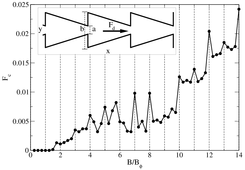
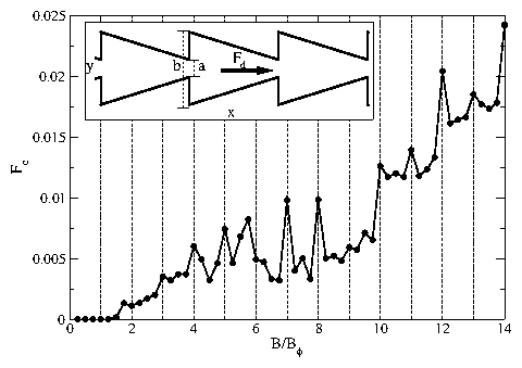
The depinning force Fc vs B/Bϕ for vortices in a periodic funnel array for driving in the +x, easy-flow direction. A series of peaks appear at matching fields of B/Bϕ = 4, 5, 7, 8, 11, 12 and 14. Weaker peaks occur at B/Bϕ = 3, 10, and 13, while peaks are absent at B/Bϕ = 2, 6, and 9. 
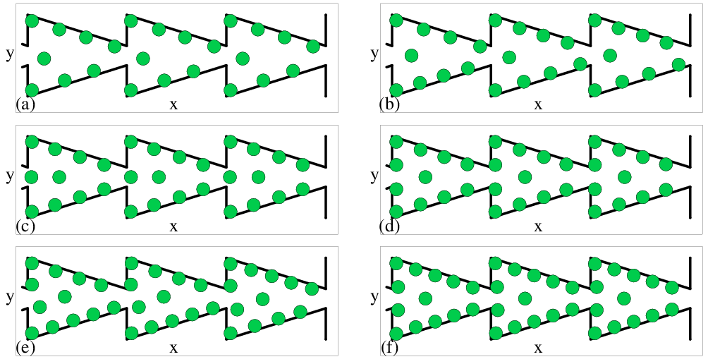
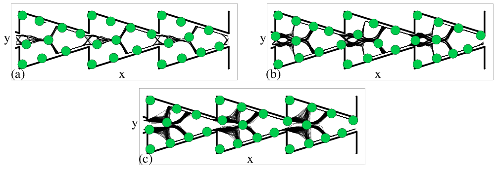
Inset: A portion of the sample showing the funnel array geometry.

IV.  COMMENSURATION EFFECTS IN THE EASY FLOW DIRECTION

In Fig. 1 we plot the the depinning force Fc for driving in the easy +x direction vs B/Bϕ, where Bϕ denotes the field at which there is one vortex per funnel. In our geometry, Fc=0 at B/Bϕ = 1.0 since each vortex can move unimpeded through the bottleneck and then flow freely along the center axis of the funnel. Fig. 1 shows peaks in Fc at B/Bϕ = 4.0, 5.0, 7.0, 8.0, 11.0, 12.0, and 14.0. Smaller peaks in Fc appear at B/Bϕ = 3.0, 10.0, and 13.0, while peaks are absent at B/Bϕ = 2.0, 6.0, and 9.0. The varying sizes and shapes of the commensuration peaks are consistent with the existence of distinct arrangements of singly quantized vortices within the funnel plaquettes at different matching fields.
Commensurability effects in two-dimensional square or triangular periodic pinning arrays can take two different forms depending on whether multiple vortices are trapped at each pinning site or whether interstitial vortices are present. If multiple vortex pinning occurs, then the vortex configuration at each matching field B/Bϕ=n, with integer n, is the same as the configuration at B/Bϕ = 1.0, but with n-quantized vortices trapped at each pinning site. The result is a peak in the critical current at every matching field.[41] Similarly, the vortex configurations at fractional fields such as B/Bϕ = 1/2 are repeated at all fields B/Bϕ=n + 1/2.[5,8] Such multi-quanta commensuration effects are very similar to the commensuration effects observed in superconducting wire networks.[42] If the pinning sites can capture a maximum of one vortex, then for fields above B/Bϕ=1, some vortices will be located in the interstitial regions and the vortex lattice structures can be different at each matching field.[3,4] At matching fields where the interstitial vortex structure is disordered, there is no peak in the critical current [3]. The magnitude and shape of the commensuration peaks show striking variations when different types of vortex crystals form at different matching fields. For example, in square pinning arrays, a square vortex lattice forms at B/Bϕ = 2.0, a less stable dimer lattice with a smaller critical current peak appears at B/Bϕ = 3.0, a very stable triangular lattice with a strong critical current peak is present at B/Bϕ = 4.0, and the partially disordered vortex structures at B/Bϕ = 6.0 and 7.0 produce no peaks in the critical current.[3]
For the asymmetric funnel array, the quasi-one-dimensional nature of the system might be expected to produce identical commensuration effects at each matching field; however, it is possible for the vortices within each funnel to distort in both the x and y directions in order to try to form triangular ordering on a local scale, and thus the response of the system differs at different matching fields. Simulations and experiments on single mesoscopic triangular superconducting samples have shown that the vortices can form triangular or partially ordered configurations at magic fillings such as B/Bϕ = 3.0, 6.0, and 10.0.[43] At these matching fields, we find weak or missing commensuration peaks in the funnel geometry, as indicated in Fig. 1. The high symmetry of these well ordered states results in poor pinning of the vortices in the easy-flow direction since it allows some vortices to simultaneously align along the x axis of the channel while closely approaching the narrow aperture of the funnel. The alignment of the vortices produces an additional x-direction force on the vortex closest to the funnel tip, permitting it to flow out of the funnel at a relatively low driving force. In contrast, at commensurate fillings where the vortices adopt partially disordered configurations or have degenerate ground states, the critical current is high. This is likely due to the lack of a well-defined easy shear direction for the disordered vortices.
Figure 1 shows a vanishing critical current at low fields which results when the vortices are able to sit along the center of the funnel channel and can flow along the channel unimpeded by the funnel geometry. The experiments of Ref. [17] revealed a finite critical depinning force at low fields. Since the experimental channels are less than λ wide, this finite critical force could be the result of a bowing effect in the center of the funnel channel that creates some effective pinning even for very low fields. The edge barrier may also be playing a role at low fields, and it is likely that some intrinsic random pinning exists throughout the entire sample which would create a finite Fc at all fields. If the intrinsic pinning is weak, it should be possible to observe the commensuration effects shown in Fig. 1. The intrinsic pinning effects can be strongly suppressed near Tc, and in a later section we show that the commensuration effects in Fig. 1 are robust at finite temperature. We also note that for colloidal particles in an optical funnel trap array, such intrinsic pinning effects would not be present.
At incommensurate fields n < B/Bϕ < n+1, due to the discreteness of the vortices the funnels are occupied by a mixture of n and n+1 vortices. The depinning force is reduced at these fields as a result of the asymmetric repulsive force experienced by a vortex at the boundary between two funnels of different occupancy. Fig. 1 indicates that peaks or enhancements of the depinning force can arise at non-matching fields such as at B/Bϕ = 3.5 and B/Bϕ=5.75; however, unlike the matching peaks, these non-matching peaks are not robust against thermal fluctuations.
Fig2.png
Figure 2: Vortex positions (dots) and funnel geometry (lines) in a small portion of the sample at different fields with no applied drive. (a) At B/Bϕ = 2.0, an aligned dimer state forms. (b) At B/Bϕ=3.0, a triangular state forms with the triangle orientation alternating in every other funnel. (c) B/Bϕ=4.0. (d) B/Bϕ=5.0. (e) At B/Bϕ=6.0, a triangular structure forms that fits well with the triangular funnel geometry and that matches the vortex configuration found in an individual mesoscopic triangular superconductor. This field also corresponds to a missing commensuration peak in Fig. 1. (f) B/Bϕ=7.0.
In Fig. 2(a-f) we illustrate the vortex configurations at zero applied drive for B/Bϕ = 2.0, 3.0, 4.0, 5.0, 6.0, and 7.0. For B/Bϕ = 2.0, Fig. 2(a) shows that each funnel captures two vortices which form a dimer state. All of the dimers are aligned in the same direction with one vortex in each dimer located at the upper left corner of the funnel and the other vortex located along the lower wall. We note that this is not the same configuration that would arise for a single isolated triangular superconductor, where the two vortices would maximize their spacing by sitting with one vortex at the tip of the triangle and the other vortex in the center of the opposing triangle wall. Interactions between vortices in adjacent funnels in our system would make such an arrangement energetically unfavorable since the vortex at the tip of the triangle would be too close to the leftmost vortex in the adjacent funnel. The tilted dimer configuration in Fig. 2(a) minimizes the vortex-vortex interactions both within a single funnel and in adjacent funnels.
The vortex dimer state in Fig. 2(a) is two-fold degenerate; in the other possible orientation, a vortex is located at the lower left corner of each funnel. In an infinitely long system at finite temperature or in the presence of quenched disorder, it is possible that domain wall excitations could form where the dimer orientation flips from one ground state to the other. In this case, it may be possible to map the dimer state to a one-dimensional Ising model which is known to have a long-range ordered ground state only at T = 0.0. The mapping of effective dimer and trimer states of particles in periodic substrates to Ising and other spin models has been proposed previously for colloids on two-dimensional periodic substrates [44] and vortices in honeycomb pinning arrays.[45] For B/Bϕ = 3.0, Fig. 2(b) shows that the three vortices in each funnel form a triangle with one vortex located in the corner of the funnel. The orientation of the triangle alternates in every other plaquette from having the upper funnel corner occupied by a vortex to having the lower funnel corner occupied by a vortex. This ground state has similarities to a one-dimensional antiferromagnetic ordering.
For B/Bϕ = 4.0, shown in Fig. 2(c), both corners of each funnel are occupied by vortices and the ground state is non-degenerate. This is the first filling at which a pronounced peak in Fc emerges, as seen in Fig. 1. The ground state at B/Bϕ = 5.0, illustrated in Fig. 2(d), is very similar to the configuration at B/Bϕ = 4.0 with the addition of one vortex in the center of the channel near the tip of the funnel, while at B/Bϕ = 6.0, shown in Fig. 2(e), there are two vortices in the center of the channel. At B/Bϕ = 7.0, Fig. 2(f) indicates that the configuration changes from states with four vortices along the walls and the remaining vortices in the center of the channel to a state with six vortices lining the walls and only one vortex in the center of the channel. Figure 1 indicates that there is a pronounced peak in Fc at B/Bϕ = 7.0 but not at B/Bϕ = 6.0. The vortex configurations at B/Bϕ = 2.0, 3.0, 4.0, 5.0, and 7.0 differ from the configurations found in isolated mesoscopic triangular superconductors;[43] however, the configuration at B/Bϕ = 6.0 is almost the same as that in an isolated triangle since the vortices can form an almost perfect triangular ordering within the funnel at this field. Since the accommodation of the triangular ordering to the boundaries is so energetically favorable, it overcomes the energy cost of placing two vortices close together near the funnel aperture with one vortex shifted slightly in the positive x-direction. Since this vortex experiences an extra force from the other vortices, the effective pinning potential at the tip of the funnel for this vortex is depressed, lowering Fc. At B/Bϕ = 7.0 this condition no longer holds since the extra vortex that had been near the funnel tip shifts to a new location along the wall, where it no longer exerts an extra force on the vortex at the center of the channel.
Fig3.png
Figure 3: Vortex positions (dots) and funnel geometry (lines) in a small portion of the sample at different fields with no applied drive. (a) B/Bϕ = 8.0. (b) B/Bϕ=9.0, where there is a missing peak in Fc. (c) B/Bϕ=10.0. (d) B/Bϕ=11.0. (e) B/Bϕ=12.0. (f) B/Bϕ=13.0.
In Fig. 3(a), the ordered vortex configuration at B/Bϕ = 8.0 has four vortices on the upper wall of each funnel and three vortices on the bottom wall, along with one vortex in the center of the channel near the wide end of the funnel. This configuration has a two-fold degenerate ground state since either the upper or the lower funnel wall could be occupied with the four vortices. At B/Bϕ = 9.0, Fig. 3(b) shows that there are now four vortices lining both the top and bottom funnel walls. The vortices on one wall are slightly more compressed than the vortices on the other wall so that the vortices near the funnel tip are not aligned in the y-direction. The wall with the stronger compression alternates from top to bottom in adjacent funnels. Figure 1 indicates that there is no peak in Fc at B/Bϕ = 9.0. The relatively low depinning threshold at this field is a result of the close proximity of a vortex near each funnel tip to the vortex in the center of the channel combined with the asymmetry of the vortex compression along the walls; the extra force experienced by the channel vortex from the less compressed wall of the funnel causes it to depin more readily. At B/Bϕ = 10, shown in Fig. 3(c), two vortices occupy the center of the channel and the remaining eight vortices line the upper and lower funnel walls in a symmetric configuration. In Fig. 3(d) we plot the configurations at B/Bϕ = 11.0, where four vortices line each funnel wall and a triangular vortex structure forms near the wide end of the funnel. At B/Bϕ = 12, Fig. 3(e) shows that an asymmetric configuration of five vortices on one funnel wall and four vortices on the other forms along with a skewed triangle of vortices in the open portion of the channel. At B/Bϕ = 13, the symmetric configuration illustrated in Fig. 3(f) forms with five vortices along each funnel wall and a triangle of vortices in the center of the channel.
Fig4.png
Figure 4: The average distance to the closest neighbor 〈dmin〉 at FD=Fc vs B/Bϕ. The line indicates a fit to 1/B.

A.  Jamming and Bottleneck Effects Due to Vortex-Vortex Interactions

Figure 1 shows that the depinning force tends to increase overall with increasing B. This is the result of a crowding effect that makes it more difficult for the vortex structure to distort in order to permit individual vortices to pass through the bottleneck. We can show that the crowding is geometrically induced by measuring the average closest neighbor distance 〈dmin〉 for the vortex configuration at the depinning force FD=Fc. To determine 〈dmin〉, we solve the all-nearest-neighbors problem with a simple algorithm. The distance from each vortex i to its closest neighbor at Rnni is dimin=|RiRinn|. Then, 〈dmin〉 = Nv−1iNvdimin. The value of 〈dmin〉 at the depinning threshold has a convincing 1/B form, as shown in Fig. 4. As expected in a system where the pinning originates from vortex-vortex interaction forces, at a given field B a vortex can depin when the driving force pushes it closer to its neighboring vortex than the average spacing between vortices. As B increases, the average vortex spacing should drop as 1/B, consistent with the behavior of 〈dmin〉. The critical force curve shown in Fig. 1 is very far from being a smooth function of B, unlike 〈dmin〉, and this simply indicates that the particular geometric arrangements of the vortices at different fields may make it easier or more difficult for two vortices to approach each other closely enough to depin.
For the most commonly studied types of pinning, such as random pinning or arrays of individual pinning sites, when the number of vortices exceeds the number of pins, the depinning force tends to decrease with increasing B due to the relative increase in the strength of the vortex-vortex interactions compared to the pinning energy. In this case, as the vortex lattice becomes stiffer, some vortices are forced to shift out of the pinning sites and occupy interstitial regions. In other words, a stiff vortex lattice cannot adjust to the pinning site configuration as well as a soft vortex lattice can. One proposed mechanism for the peak effect observed in superconductors with random pinning is a softening of the vortex lattice due either to thermal fluctuations or to changes in λ which increase the effectiveness of the pinning. In the funnel geometry we consider here, depinning does not require the vortices to overcome the pinning strength of individual pinning sites. Instead, the vortices depin once they are able to overcome the vortex-vortex interactions blocking the passage of individual vortices through the funnel tips.
A system that becomes less mobile due to increased interactions among the particles is said to be jammed.[34,46,35,47] Studies on systems with short range interactions where a single probe particle is pushed through a collection of other particles in the absence of pinning have shown that the probe particle motion at a finite and constant driving force Fd becomes slower for increasing particle density, and at a critical density the probe particle becomes stuck or jammed.[35,26,48] In this jammed state, a critical driving force Fc must be applied to unjam the probe particle, and this critical force monotonically increases with increasing density.[48] The critical force is analogous to the depinning force needed to move the vortices through the funnels in our system, which also shifts to higher values as the vortex density increases. There are many similarities between Fig. 1 and the behavior of jamming in colloidal systems. At very low densities, the critical depinning force drops to zero since the vortices are so far apart that they interact only extremely weakly. Previous studies of probe particles in systems with longer range particle-particle interactions found that a finite depinning force, similar to a jamming effect, exists even at low densities and increases monotonically with particle density.[49] A key ingredient for jamming in our system is that a portion of the vortices must remain immobile. The vortices lining the walls of the funnel are held in place due to the strength of the repulsive vortex-vortex interactions; when one of these vortices moves toward the tip of the funnel, it experiences a barrier due to the compression of the vortices at the funnel tip, providing a finite depinning force. Vortices away from the funnel walls are also pinned by means of this compressive repulsion. If the funnel walls did not converge, but instead remained a fixed distance apart, the depinning force would be absent. In experiments and simulations on straight channels where there are vortices both inside and outside the channels, the vortices outside of the channel are strongly pinned and create a periodic potential modulation for the vortices within the channel which allow the channel vortices to be pinned.[50] For the funnel geometry we consider, additional immobile vortices outside of the channel are not needed to create an effective periodic pinning potential. In ratchet channel geometries [16] there are strongly pinned vortices outside of the channels; however, we do not expect the presence of such vortices to qualitatively affect the results we report here. For colloids moving through an asymmetric optical trap array, it would be possible to remove all colloids outside of the channel so that particles are present only inside the ratchet channel.
Fig5.png
Figure 5: The average velocity 〈Vx〉 vs B/Bϕ at FD = 0.03, 0.025, 0.02, 0.015, 0.01, and 0.005 (from top to bottom).
To quantify the greater difficulty with which vortices flow at higher vortex densities, we examine the average normalized vortex velocity 〈Vx〉 versus B/Bϕ for different values of the driving force FD. In Fig. 1 the initial depinning force Fc was determined by the initial onset of vortex flow; however, the normalized velocity can be taken at any value of FD and in Fig. 5 we plot 〈Vx〉 versus B/Bϕ for FD = 0.03, 0.025, 0.02, 0.015, 0.01, and 0.005. In all cases, 〈Vx〉 decreases with increasing B/Bϕ expect for some small oscillations caused by commensuration effects. At FD=0.005, 〈Vx〉 = 0 for those fields at which Fc > FD. The reason that the overall flow velocity decreases for increasing B is that the flow patterns organize in such a way that only one vortex at a time is able to pass through the funnel tip, as will be shown later. This is a result of the very large energy cost that would be associated with the passage of two or more vortices through the tip simultaneously. The single passage constraint causes the flow rate of vortices through the system to be roughly constant for fixed FD, such that for a number of moving vortices Nm, we find Nm ∝ 〈VxB. For fixed Nm, we obtain 〈Vx〉 ∝ 1/B, which is approximately the behavior shown in Fig. 5. The results in Figs. 1 and 5 show that jamming phenomena can be realized in superconducting systems or other systems of particles with intermediate to long range interactions. Further, since stronger pinning is often a desirable feature for many applications of superconductors, some of the concepts from studies of jammed systems could be employed to increase the effective pinning strength in a device.
Fig6.png
Figure 6: The vortex velocity 〈Vx〉 vs FD for B/Bϕ = 2.0, 2.25, 2.5, and 2.75 (from top to bottom). Here the average velocity decreases with increasing B.

V.  DYNAMIC PHASES UP TO B/Bϕ = 8.0

We next examine the different vortex dynamical phases that can arise in the funnel geometry. In Fig. 6 we plot 〈Vx〉 versus FD for B/Bϕ = 2.0, 2.25, 2.5, and 2.75. The depinning force increases with increasing B/Bϕ over this field range, as was seen in Fig. 1, and above depinning 〈Vx〉 for a particular value of FD decreases as more vortices are added to the system, as was shown in Fig. 5.
Fig7.png
Figure 7: The vortex positions (dots), funnel geometry (heavy lines), and vortex trajectories (light lines) in a small portion of the sample at FD = 0.01 for B/Bϕ = (a) 2.0, (b) 2.25, (c) 2.5, (d) 2.75, (e) 3.0, and (f) 3.25. Here the flow at the commensurate fields is highly ordered.
In Fig. 7 we plot the vortex trajectories at fixed FD=0.01 for B/Bϕ = 2.0, 2.25, 2.5, 2.75, 3.0, and 3.25. The flow is ordered at B/Bϕ = 2.0 and B/Bϕ=3.0 in Fig. 7(a) and Fig. 7(e). The vortices move in fixed trajectories and continuously maintain the same neighbors, indicating that all of the vortices are moving. For B/Bϕ = 2.25, 2.5, and 2.75 in Fig. 7(b,c,d), the trajectories become increasingly disordered and the vortices no longer keep the same neighbors over time, indicative of plastic flow. The disordered nature of the flow permits the vortices to explore larger regions of phase space, including regimes in which some of the vortices move much more slowly than others or become temporarily pinned.
Fig8.png
Figure 8: 〈Vx〉 vs FD for B/Bϕ = 3.0, 3.25, 3.5, and 3.75 (from top right to bottom right), showing the same trends as in Fig. 5.
Fig. 7(f) indicates that at B/Bϕ=3.25, the vortex trajectories are more disordered than at B/Bϕ = 3.0. In Fig. 8 we plot 〈Vx〉 vs FD for B/Bϕ = 3.0, 3.25, 3.5, and 3.75, which show the same trend observed at and above the second matching field. The value of 〈Vx〉 at a fixed FD above the depinning threshold decreases with increasing B/Bϕ and the vortex flow becomes partially disordered at the incommensurate fields.
Fig9.png
Figure 9: 〈Vx〉 vs FD for (a) B/Bϕ = 4.0. (b) B/Bϕ=4.25. (c) B/Bϕ=4.5 showing a two step depinning process with a cusp near FD = 0.008 where 〈Vx〉 decreases with increasing FD. (d) B/Bϕ=4.75 showing some small steplike features.
Fig10.png
Figure 10: Vortex portions (dots), funnel geometry (heavy lines), and vortex trajectories (light lines) in a small portion of the sample. (a) B/Bϕ = 4.0 at FD=0.01 where an ordered flow occurs. (b) The initial ordered flow at B/Bϕ = 4.5 and FD=0.008, below the cusp in 〈Vx〉 in Fig. 9(c), where only the vortices along the top wall are moving. (c) The disordered flow for B/Bϕ=4.5 at FD=0.017, above the cusp in 〈Vx〉 in Fig. 9(c), where all of the vortices are moving. (d) The high drive phase at FD = 0.0275 for B/Bϕ = 4.5. (e) The initial disordered flow at FD=0.008 for B/Bϕ = 4.75. (f) The flow at FD=0.01 for B/Bϕ=4.75, below the step in 〈Vx〉 which occurs near FD = 0.012 in Fig. 9(d). For drives above the step in 〈Vx〉 at this field, the vortex flow resembles the flow shown in panel (a).
For B/Bϕ > 4.0, the transport becomes more complicated and transitions between distinct dynamical phases begin to occur. The moving phases for B/Bϕ > 4.0 are generally characterized as plastic since a portion of the vortices can remain immobile. We find both ordered plastic motion, where the trajectories of the mobile vortices follow a fixed path, and disordered plastic flow phases where the vortex motion is more chaotic and the vortices follow many different paths. In Fig. 9(a-d) we plot 〈Vx〉 versus FD for B/Bϕ = 4.0, 4.25, 4.5, and 4.75. At B/Bϕ = 4.0, Fig. 9(a) indicates that there is a single well defined depinning transition where the vortices flow elastically, as illustrated in Fig. 10(a). For B/Bϕ = 4.25, the value of Fc is depressed as seen in Fig. 9(b). Here there are no sharp jumps in the transport curve, and the vortex motion resembles that observed at B/Bϕ = 4.0 but with some additional fluctuations in the vortex trajectories.
At B/Bϕ = 4.5, a two step depinning process occurs as shown in Fig. 9(c). Initially, only one ordered channel of moving vortices forms along one of the funnel walls while the remaining vortices are immobile. This is illustrated in Fig. 10(b) for a simulation in which the vortices along the upper funnel wall depinned first; depending upon the initial random fluctuations, it is also possible for the vortices along the lower wall to depin first. The remaining vortices depin near FD=0.008, where a cusp feature appears in 〈Vx〉. At the cusp, the average vortex velocity decreases with increasing FD, creating a region of negative differential conductivity where dVx〉/dFD < 0.0. The negative differential conductivity at B/Bϕ = 4.5 is not as pronounced as that observed in simulations and experiments with square pinning arrays; [9,10] however, we find that the type of negative differential conductivity illustrated in Fig. 9(c) is a common feature at a number of the higher order incommensurate fillings we have examined in the funnel geometry. In contrast, for the square pinning array the negative differential conductivity occurs only near the first matching field. This indicates that it may actually be easier to observe negative differential conductivity in a funnel geometry than in a square pinning array. Above the cusp at FD=0.008, Fig. 9(c) shows that 〈Vx〉 smoothly increases with increasing FD.
In Fig. 10(b) we show that the vortex flow below the cusp in 〈Vx〉 at B/Bϕ = 4.5 and FD=0.008 is ordered with only a single channel of vortex flow. Figure 10(c) indicates that for the same field at FD=0.017, above the cusp in 〈Vx〉, the vortices flow in disordered paths, each of which predominantly runs along either the upper or lower funnel wall. The transition from only a single flowing channel to effectively two flowing channels of vortices at the second depinning transition associated with the cusp in 〈Vx〉 causes a drop in the mobility of the vortices due to the competition between the two channels for passing a vortex through the bottleneck of the funnel. Only a single vortex can fit through the bottleneck at a time, but vortices in the upper and lower flowing channels do not arrive at the bottleneck at synchronized times due to the unequal distribution of vortices between the two effective channels which causes the two channels to flow at different average speeds. As a result, a vortex in one channel may reach the bottleneck too soon while a vortex from the other channel is still moving through the bottleneck, forcing the vortices in the first channel to move more slowly until the vortex in the second channel has exited the bottleneck and freed it for passage of a vortex in the first channel. As FD increases, the difference in flow speed for the two unequally populated channels of moving vortices decreases until it is small enough that the flow of the two channels becomes synchronized on average and a much more orderly passage of vortices through the bottleneck occurs, alternating between the two channels. In this case, the disordered trajectories become smoother, as shown for FD = 0.0275 in Fig. 10(d).
For B/Bϕ = 4.75, Fig. 9(d) shows that there are several small steps in the 〈Vx〉 versus FD curve which correspond to changes in the flow. In Fig. 10(e), the initial flow for this field at FD=0.008 is partially disordered. By FD=0.01, shown in Fig. 10(f), a transition to a more ordered flow state has occurred where there are two possible paths for vortices to follow in the lower channel. At higher drives, one of these two lower paths closes, corresponding to the jump in 〈Vx〉 near FD = 0.012, and the flow at higher drives resembles that shown in Fig. 10(a).
Fig11.png
Figure 11: 〈Vx〉 vs FD for (a) B/Bϕ = 5.0. (b) B/Bϕ=5.25. (c) B/Bϕ=5.5. (d) B/Bϕ=5.75.
Fig12.png
Figure 12: The structural transition that occurs in the single stage depinning transition at B/Bϕ=5.0 shown in a small portion of the sample. Dots: vortex positions; heavy lines: funnel geometry; light lines: vortex trajectories. (a) Right before depinning, at FD=0.006, there are four vortices lining the walls and one vortex located in the center of the channel near the funnel tip. (b) The first rearrangement just below FD=0.0075 occurs when the center vortices move through the aperture in the positive x direction and pass into the adjacent funnels. (c) At depinning, which occurs at FD=0.0075, these center vortices move against the funnel walls in an alternating pattern associated with a transient flow. (d) Above depinning at FD=0.012, the vortices flow strictly along the funnel walls.
At B/Bϕ = 5.0 there is a single depinning transition, as illustrated in the plot of 〈Vx〉 versus FD in Fig. 11(a). Right at the depinning transition, the vortices undergo a structural transition which is highlighted in Fig. 12. The vortex configuration for drives well below depinning consists of four vortices arranged symmetrically along the funnel walls with a fifth vortex in the center of the channel near the funnel tip, as shown in Fig. 12(a). At the onset of depinning, illustrated in Fig. 12(b) just below FD=0.0075, the vortices at the funnel tips move in the positive x direction and shift into the adjacent funnel. At depinning, which occurs at FD=0.0075, Fig. 12(c) indicates the rearrangement that occurs when the center vortices move against one of the funnel walls in an alternating pattern. Above depinning, as shown in Fig. 12(d) for FD=0.012, the vortices flow strictly along the funnel walls in two channels that never mix.
Fig13.png
Figure 13: The vortex positions (dots), funnel geometry (heavy lines), and vortex trajectories (light lines) in a small portion of the sample. (a) The initial flow at FD=0.006 for B/Bϕ = 5.25. (b) The initial depinning at FD=0.012 for B/Bϕ = 5.75. (c) The trajectories in the fluctuating phase for FD=0.019 at B/Bϕ = 5.75. (d) The high drive ordered phase at FD=0.032 for B/Bϕ = 5.75.
At B/Bϕ = 5.25, 5.5, and 5.75, shown in Fig. 11(b), 11(c), and 11(d), respectively, there can be multiple dynamical transitions between ordered and disordered flow phases. At B/Bϕ = 5.25, the flow at large FD is very similar to that shown for B/Bϕ = 5.0 in Fig. 12(d); however, the flow initiates at a much lower drive and takes the form of an ordered winding channel in which about 40% of the vortices are moving, as shown in Fig. 13(a). As the vortices in the winding channel move through the system, the vortices pinned along the funnel walls undergo an oscillatory motion which is most easily seen in Fig. 13(a) for the pinned vortex near the center of each long funnel wall. This oscillation is a response to the passage of an individual vortex through the flowing channel; the pinned vortex shifts in the positive x direction as the moving vortex approaches, and shifts back again after the moving vortex has passed. The vortices at the corners of the funnel undergo little to no shift. In Fig. 11(d) at B/Bϕ = 5.75 the transitions between different dynamical phases are associated with changes in the fluctuations of the velocity signal. At this filling, the sharp depinning transition takes the system into the ordered braiding flow phase illustrated in Fig. 13(b), a state with low levels of velocity fluctuations. A transition to a highly fluctuating phase occurs near FD = 0.15 and corresponds to the onset of the disordered flow phase illustrated in Fig. 13(c). For higher drives, a transition to an ordered phase occurs near FD=0.0225 when the trajectories become partially ordered. A velocity jump near FD=0.025 marks the transition to the completely ordered flow phase shown in Fig. 13(d).
Fig14.png
Figure 14: 〈Vx〉 vs FD for (a) B/Bϕ = 6.0. (b) B/Bϕ = 6.75.
Fig15.png
Figure 15: The vortex positions (dots), funnel geometry (heavy lines), and vortex trajectories (light lines) in a small portion of the sample. (a) The initial motion at FD=0.006 for B/Bϕ = 6.0. (b) The flow above depinning at FD=0.008 for B/Bϕ = 6.0. (c) The flow at FD=0.019 for B/Bϕ = 6.0. (d) The flow at FD=0.028 for B/Bϕ = 6.0. (e) The ordered vortex flow at FD=0.025 for B/Bϕ=6.75, below the cusp in 〈Vx〉 vs FD seen in Fig. 14(b). (f) The disordered flow at FD=0.028 for B/Bϕ=6.75, just after the cusp in 〈Vx〉.
At B/Bϕ = 6.0, where a commensuration peak in Fc was missing in Fig. 1, the velocity-force curve shows a single depinning transition into a random flow phase, as shown in Fig. 14(a). No sharp transitions between different phases appear; however, the general form of the vortex flow changes gradually as FD increases. Figure 15(a) shows an initial shift in vortex positions occurring at a drive just below the depinning transition. The vortex at the tip of the leftmost funnel has pushed the vortex at the base of the adjacent funnel into a position along the lower wall in a pattern that repeats every two funnel plaquettes, indicating that the vortices in the center of the channel were not well pinned, resulting in lack of a peak in Fc at this field. Just above depinning, shown at FD=0.008 in Fig. 15(b), a disordered flow occurs in which the two vortices at the corners of each funnel do not participate. Although the flow is disordered, there are clearly defined regions inside the funnels which the vortices completely avoid, as shown by the lack of trajectories passing through large areas of the funnels. As FD is further increased, the trajectories become increasingly disordered and the vortices in the corners of the funnels begin to take part in the motion, as shown in Figs. 15(c,d).
More clearly defined transitions between ordered and disordered flow states occur at B/Bϕ = 6.25, 6.5, and 6.75, as illustrated in Fig. 14(b) for B/Bϕ=6.75. The transitions are characterized by cusp structures in 〈Vx〉 associated with negative differential conductivity. Fig. 15(e) shows the initial ordered flow at FD=0.028 for B/Bϕ=6.75, below a pronounced cusp in 〈Vx〉. Here the two vortices in the corners of each funnel remain immobile so that the flow is actually plastic. These vortices become mobile at the transition to the disordered phase, illustrated at FD=0.028 in Fig. 15(e). A similar set of dynamics appears at B/Bϕ = 6.25 and B/Bϕ=6.5. For driving forces higher than those we have examined, it is possible that further dynamical transitions could occur at which different ordered phases arise.
Fig16.png
Figure 16: 〈Vx〉 vs FD for (a) B/Bϕ = 7.0 and (b) B/Bϕ = 7.75, where three distinct moving phases appear.
Fig17.png
Figure 17: The vortex positions (dots), funnel geometry (heavy lines), and vortex trajectories (light lines) in a small portion of the sample. (a) The vortex flow state at FD=0.014 for B/Bϕ = 7.0. (b) The braided flow phase at FD=0.008 for B/Bϕ = 7.75. (c) The second flow phase at FD=0.011 for B/Bϕ = 7.75. (d) The third flow phase at FD=0.021 for B/Bϕ = 7.75.
Depinning at B/Bϕ=7.0 occurs in a single step, as illustrated in Fig. 16(a) where we plot 〈Vx〉 versus FD. At this field, Fig. 1 indicates that there is a peak in Fc. Above depinning, the vortices flow in the ordered pattern shown in Fig. 17(a), where two vortices remain pinned in the corners of each funnel. For drives FD > 0.3 higher than those we consider here, a transition to a disordered flow state may occur once the drive is large enough to cause the two immobile vortices to depin. At B/Bϕ = 7.25, 7.5, and 7.75, multiple steps occur in the velocity-force curves, as illustrated in Fig. 16(b) for B/Bϕ = 7.75. Each step is associated with a distinct type of ordered flow. At low drives, we find the braided flow shown in Fig. 17(b) at FD=0.008. Above the first low step in 〈Vx〉 near FD=0.01, an alternating braided flow occurs in which every other plaquette contains two possible flow paths along the lower funnel wall, as illustrated in Fig. 17(c) at FD=0.011. Above the second larger step in 〈Vx〉 near FD=0.012, the completely ordered flow phase shown in Fig. 17(d) at FD=0.021 occurs.
Fig18.png
Figure 18: 〈Vx〉 vs FD for (a) B/Bϕ = 8.0, (b) B/Bϕ=8.25, (c) B/Bϕ=8.5, and (d) B/Bϕ=8.75.
Fig19.png
Figure 19: The vortex positions (dots), funnel geometry (heavy lines), and vortex trajectories (light lines) in a small portion of the sample. (a) The ordered flow phase at FD=0.014 for B/Bϕ = 8.0. (b) The disordered flow at FD=0.017 for B/Bϕ = 8.5. (c) The initial partially ordered flow phase at FD=0.008 for B/Bϕ = 8.75. (d) The disordered flow phase with two immobile vortices in the corners of each funnel at FD=0.025 for B/Bϕ = 8.75.

VI.  DYNAMICS AT HIGHER FIELDS B/Bϕ ≥ 8

For higher fields B/Bϕ ≥ 8.0 we observe the same trends found for fields just below B/Bϕ = 8.0. The integer matching fields typically display a single ordered flow phase, while at the incommensurate fields, multiple flow phases occur with ordered-ordered or ordered-disordered flow transitions. Another trend is that as the field increases, the number of immobile vortices appearing in the ordered flow phases increases. In Fig. 18 we plot 〈Vx〉 versus FD for B/Bϕ = 8.0, 8.25, 8.5, and 8.75, where the trend outlined above can be seen. There is a single depinning step in Fig. 18(a) at B/Bϕ = 8.0 into the ordered flow phase shown in Fig. 19(a) at FD=0.014 where two vortices remain pinned at the corners of each funnel. Figure 19(b) shows the disordered flow at the higher drive FD=0.017 for B/Bϕ = 8.5. At this field, there is a transition near FD=0.025 to an ordered phase with vortex trajectories that are very similar to those shown in Fig. 19(a) for B/Bϕ = 8.0. The initial flow at B/Bϕ = 8.75 is partially ordered with four immobile vortices in each funnel plaquette, as shown at FD=0.008 in Fig. 19(c). At higher drives for this field, the flow becomes disordered but only two of the immobile vortices begin to move, leaving two vortices immobile in the corners of each funnel, as shown in Fig. 19(d) for FD=0.025.
Fig20.png
Figure 20: 〈Vx〉 vs FD for (a) B/Bϕ = 9.0 and (b) B/Bϕ = 9.75.
Fig21.png
Figure 21: The vortex positions (dots), funnel geometry (heavy lines), and vortex trajectories (light lines) in a small portion of the sample at B/Bϕ=9.0 showing braided flows. (a) First flow regime shown at FD=0.01. (b) Second flow regime shown at FD=0.014. (c) Third flow regime shown at FD=0.023.
Fig22.png
Figure 22: The vortex positions (dots), funnel geometry (heavy lines), and vortex trajectories (light lines) in a small portion of the sample. (a) The initial motion at FD=0.008 for B/Bϕ = 9.75. (b) The second flow phase at FD=0.012 for B/Bϕ = 9.75. (c) The higher drive ordered flow phase at FD=0.028 for B/Bϕ = 9.75. (d) The flow at FD=0.017 for B/Bϕ = 11.0. (e) A complex partially ordered flow pattern at FD=0.017 for B/Bϕ = 11.25. (f) A higher drive ordered alternating flow pattern at FD=0.025 for B/Bϕ = 11.75.
We find a distinctive integer matching field at which there is not merely a single dynamic flow phase state. This field, B/Bϕ=9.0, also fails to produce a depinning peak as shown in Fig. 1. We plot 〈Vx〉 versus FD for B/Bϕ=9.0 in Fig. 20(a), which indicates that there are three distinct moving phases. All three phases involve braided vortex flows, but the details of the braiding and the number of vortices participating in the flow varies as a function of drive, as shown in Fig. 21 where the three different braided flows are illustrated. The suppression of the depinning peak at B/Bϕ=9.0 is related to the suppression of the peak at B/Bϕ=6.0. At each of these fields, the system exhibits an instability in which the number of vortices present in the center of the channel for zero applied drive is different than the number of vortices that can be stabilized along the center of the channel just above depinning. At B/Bϕ=6, in each funnel plaquette there are two vortices positioned along the center line of the channel at zero drive, but under finite drive one of these vortices moves against the funnel wall, leaving only one vortex in the center of the channel. This transition can be seen by comparing Fig. 2(e) with Fig. 15(a,b). At this filling, there is only a small energy difference between placing two vortices at the center of the channel and placing only one vortex at the center of the channel with the other vortex against the funnel wall. This produces an instability which contributes to the disordered flow we find at B/Bϕ=6. An opposite transition occurs for B/Bϕ=9. As seen in Fig. 3(b) and Fig. 21(a), there is only one vortex per plaquette in the center of the channel at zero applied drive, but above depinning a second vortex moves into the center of the channel and is stabilized there. The existence of this change in the occupancy of the center of the channel at depinning from one to two or two to one is associated with the suppression of commensuration peaks in the critical depinning force at the fields B/Bϕ=6 and B/Bϕ=9 seen in Fig. 1.
A series of flow transitions also occurs at B/Bϕ=9.75 in Fig. 20(b), corresponding to the dynamical flows illustrated in Fig. 22(a,b,c). In the initial flow phase at low drives, Fig. 22(a) indicates that only a portion of the vortices are moving in a path that passes through the bottom half of each funnel, forming a single flowing channel. At higher drives a transition to the symmetric flow state illustrated in Fig. 22(b) occurs. At still higher drives, an intermediate disordered phase appears before the flow reorders into the state shown for FD=0.028 in Fig. 22(c), where there are two immobile vortices on the bottom half of each funnel and one immobile vortex on the top half of the funnel, with flow occurring through two well-defined channels.
At higher fields, similar dynamical regimes occur and larger numbers of vortices can become immobile along the funnel walls, such as at B/Bϕ = 10 where there is a single step depinning transition into a state with four immobile vortices in each funnel. It is also possible for vortices to be immobilized in the center of the channel rather than along the funnel walls, as illustrated for B/Bϕ=11.0 in Fig. 22(d). At this field, a single step depinning transition occurs into the state shown where a total of three vortices are immobilized: two in the corners of the funnel and one right in the funnel center. As B/Bϕ increases, additional partially ordered phases occur with increasingly intricate flow patterns such as the one shown in Fig. 22(e) at B/Bϕ = 11.25. We also find phases with asymmetric flow where the asymmetry alternates from one funnel to the next, such as the state illustrated in Fig. 22(f) for B/Bϕ = 11.75. Here the leftmost funnel contains two flowing channels of vortices interacting with the upper funnel wall and one channel interacting with the lower funnel wall, while in the middle funnel this flow pattern is reversed.
We expect the trends described above to continue for higher matching fields. Eventually, however, there may be a crossover to a state where the vortex lattice constant is smaller than the width of the funnel aperture, at which point it would be possible to move two vortices through the funnel tip at the same time without much of an additional energy cost. In this case, the average velocity might sharply increase since the flow in the aperture would transition from one-dimensional to quasi-two-dimensional, and it may be possible that further oscillations in the average velocity would arise at even higher fields as larger groups of vortices could pass through the aperture simultaneously for increasing magnetic field values.
Fig23.png
Figure 23: The power spectrum S(ν) versus frequency ν in inverse simulation time steps. Lower curve: The ordered phase at FD=0.02 for B/Bϕ = 5.0, where a series of peaks occurs due to the periodic velocity signal of the vortices. Upper curve: The disordered flow phase at FD=0.02 for B/Bϕ = 6.0, where a broadband noise signal arises with a 1/ν2.5 form. The same types of spectra appear for ordered and disordered flow phases at other fields.

VII.  NOISE MEASUREMENT AND TEMPERATURE EFFECTS

With current experimental noise measurement techniques, it should be possible to characterize the difference between ordered and disordered flow phases. The vortex velocities we measure in our simulations are proportional to the experimentally measured vortex voltage signal, which can be analyzed using the power spectrum defined as
S(ν) =

1


V(t)ei 2πνt dt

2

 
(2)
In Fig. 23 we plot S(ν) for B/Bϕ = 5.0 at FD=0.02 in a regime of ordered flow. We find narrow band noise peaks at the characteristic frequencies of the ordered oscillatory motion of the vortices. Also plotted in Fig. 23 is S(ν) for B/Bϕ = 6.0 at FD=0.02, where the vortex flow is disordered. Here the power spectrum has a broad band or 1/fα noise characteristic with α = 2.5. In general, for other values of B/Bϕ, the ordered phases produce narrow band spectra while the disordered phases produce broad band noise signals. The appearance of the narrow band noise in the ordered phase implies that phase locking phenomena could be induced by adding an ac drive component to the dc driving force. When the frequency of the ac drive matches the intrinsic or higher harmonic frequencies of the moving vortices in the ordered phase, a series of steps should appear in the velocity force curves.
We next consider the effect of temperature. In periodic pinning arrays, the most pronounced matching field peaks observed in experiments occur at temperatures near Tc. This has been attributed to the thermal suppression of the intrinsic pinning in the sample that competes with the periodic pinning. Another factor that could play a role is that the vacancies or interstitials present in the vortex lattice away from commensurate fields can be relatively mobile under thermal activation, and so increasing the temperature could depress the depinning force to a larger degree at incommensurate fields than at commensurate fields where vacancies or interstitials are not present. We find that for a temperature of T=0.1, which is well below the melting temperature of the vortex lattice, the depinning force peaks at the commensurate fields are robust while the depinning force at the incommensurate fields is depressed. The peaks in Fc that appear at B/Bϕ = 4.5 and B/Bϕ=5.5 for T = 0 are absent at T=0.1, indicating that for finite temperatures, pronounced peaks are only observable at the matching fields whereas submatching field peaks are less robust. The general trend of increasing Fc with increasing B/Bϕ also remains robust at finite temperature.

VIII.  DISCUSSION

Although our work is focused on a superconducting vortex system, we expect our results to be general for other systems of particles with repulsive interactions. For example, in colloidal systems where the volume density is sufficiently low that steric contact of the colloidal particles does not occur, many of the same results should still apply. One aspect of the vortex system that we do not take into account is the possibility of multi-quanta vortex formation under certain conditions. In static systems, the formation of giant vortices has been observed in cases where the giant vortices produce a higher symmetry of the vortex configuration, such as in quasiperiodic pinning arrays.[51] It is possible that dynamical multi-quanta vortices could form in a funnel geometry. For example, if two vortices are forced into close proximity near the funnel tip, they could merge to form a two-quanta vortex which would then pass through the funnel tip. The formation of such dynamical multi-quanta vortices could produce interesting signatures in the transport curves. The experimental system closest to the system studied here is periodic asymmetric channel geometries [16] where small oscillations in the critical current due to commensuration effects were observed. Since these commensuration effects were very weak, it is possible that they were due to edge effects. More recent experiments with geometries that avoid the effect of edges have now revealed much more prominent commensuration effects,[17] indicating that some of the phases we observe may be occurring in this system.

IX.  SUMMARY

In summary, we have used numerical simulations to examine the vortex configurations and dynamics in a periodic funnel array. The vortex configurations we observe are generally different from those found for a single isolated triangular sample due to the coupling between vortices in adjacent funnels. As a function of field we find a series of depinning threshold peaks at the matching fields where the vortex configurations are ordered. In some cases, matching peaks are missing due to the fact that the vortex configuration contains pairs of vortices that are located close together near the funnel apertures. We also observe a general increase in the depinning threshold with increasing vortex density, which is opposite from the normal trend for vortices in two-dimensional pinning arrays where the vortices are directly trapped by pinning sites. In the funnel geometry, the pinning is a result of the repulsive vortex-vortex interaction forces, and as the vortex density increases it becomes more difficult for the vortices to overcome these repulsive forces and flow through the funnel tip. We also find a rich variety of dynamical phases, including ordered elastic and ordered plastic phases where the vortices follow fixed trajectories and disordered phases where vortices mix chaotically. The phases generally organize in such a way that only one vortex passes through the tip of the funnel at a time. Due to this constraint, the average velocity of an individual vortex decreases with increasing field such that the sum of the velocities of all of the vortices at fixed drive remains close to constant for increasing field rather than increasing with increasing field. This behavior is similar to the response of grains in an hourglass. Transitions between the different dynamical phases appear as jumps or cusps in the velocity-force curves, and there are even regimes where the average vortex motion decreases with increasing drive, producing a negative differential conductivity. At higher fields, moving states can form in which a single vortex remains immobile at the center of a funnel while other vortices flow around it. In general, ordered flow phases occur at the matching fields, while at non-matching fields the flow is disordered for at least some regime of driving forces. The ordered phases are associated with sharp narrow band or washboard velocity noise signals while the disordered phases have 1/fα velocity noise spectra. Our results should also be generalizable to other systems of repulsively interacting particles moving through a funnel geometry, such as colloids or Wigner crystals.
We thank B. Plourde for helpful discussions. This work was carried out under the auspices of the NNSA of the U.S. DoE at LANL under Contract No. DE-AC52-06NA25396.

References

[1]
M. Baert, V.V. Metlushko, R. Jonckheere, V.V. Moshchalkov, and Y. Bruynseraede, Phys. Rev. Lett. 74, 3269 (1995); K. Harada, O. Kamimura, H. Kasai, T. Matsuda, A. Tonomura, and V.V. Moshchalkov, Science 274, 1167 (1996).
[2]
J.I. Martín, M. Vélez, J. Nogués, and I.K. Schuller, Phys. Rev. Lett. 79, 1929 (1997); D.J. Morgan and J.B. Ketterson, Phys. Rev. Lett. 80, 3614 (1998); J.E. Villegas, M.I. Montero, C.-P. Li, and I.K. Schuller, Phys. Rev. Lett. 97, 027002 (2006).
[3]
C. Reichhardt, C.J. Olson, and F. Nori, Phys. Rev. B 57, 7937 (1998).
[4]
G.R. Berdiyorov, M.V. Milosevi\'c, and F.M. Peeters, Phys. Rev. Lett. 96, 207001 (2006).
[5]
S.B. Field, S.S. James, J. Barentine, V. Metlushko, G. Crabtree, H. Shtrikman, B. Ilic, and S.R.J. Brueck, Phys. Rev. Lett. 88, 067003 (2002); A.N. Grigorenko, G.D. Howells, S.J. Bending, J. Bekaert, M.J. Van Bael, L. Van Look, V.V. Moshchalkov, Y. Bruynseraede, G. Borghs, I.I. Kaya, and R.A. Stradling, Phys. Rev. B 63, 052504 (2001).
[6]
V. Metlushko, U. Welp, G.W. Crabtree, Z. Zhang, S.R.J. Brueck, B. Watkins, L.E. DeLong, B. Ilic, K. Chung, and P.J. Hesketh, Phys. Rev. B 59, 603 (1999).
[7]
E. Rosseel, M. Van Bael, M. Baert, R. Jonckheere, V.V. Moshchalkov, and Y. Bruynseraede, Phys. Rev. B 53, R2983 (1996).
[8]
G. Karapetrov, J. Fedor, M. Iavarone, D. Rosenmann, and W.K. Kwok, Phys. Rev. Lett. 95, 167002 (2005).
[9]
C. Reichhardt, C.J. Olson, and F. Nori, Phys. Rev. Lett. 78, 2648 (1997); C. Reichhardt, C.J. Olson, and F. Nori, Phys. Rev. B 58, 6534 (1998).
[10]
V.R. Misko, S. Savel'ev, A.L. Rakhmanov, and F. Nori, Phys. Rev. B 75, 024509 (2007).
[11]
J. Gutierrez, A.V. Silhanek, J. Van de Vondel, W. Gillijns, and V.V. Moshchalkov, Phys. Rev. B 80, 140514(R) (2009).
[12]
Z. Xiao et al., to be published.
[13]
C.-S. Lee, B. Jankó, I. Derényi, and A.-L. Barabási, Nature (London) 400, 337 (1999).
[14]
Q. Lu, C.J. Olson Reichhardt, and C. Reichhardt, Phys. Rev. B 75, 054502 (2007).
[15]
J.F. Wambaugh, C. Reichhardt, C.J. Olson, F. Marchesoni, and F. Nori, Phys. Rev. Lett. 83, 5106 (1999).
[16]
K. Yu, T.W. Heitmann, C. Song, M.P. DeFeo, B.L.T. Plourde, M.B.S. Hesselberth, and P.H. Kes, Phys. Rev. B 76, 220507(R) (2007).
[17]
K. Yu, M.B.S. Hesselberth, P.H. Kes, and B.L.T. Plourde, arxiv:1003.0387.
[18]
C.C. de Souza Silva, J. Van de Vondel, M. Morelle, and V.V. Moshchalkov, Nature (London) 440, 651 (2006).
[19]
J.E. Villegas, E.M. Gonzalez, , M.P. Gonzalez, J.V. Anguita, and J.L. Vicent, Phys. Rev. B 71, 024519 (2005).
[20]
C.J. Olson Reichhardt and C. Reichhardt, Physica C 432, 125 (2005).
[21]
E.M. Gonzalez, N.O. Nunez, J.V. Anguita, and J.L. Vicent, Appl. Phys. Lett. 91, 062505 (2007).
[22]
L. Dinis, E.M. González, J.V. Anguita, J.M.R. Parrondo, and J.L. Vicent, New J. Phys. 9, 366 (2007).
[23]
For a review, see P. Reimann, Phys. Rep. 361, 57 (2002).
[24]
B.L.T. Plourde, IEEE Trans. Appl. Supercond. 19, 3698 (2009).
[25]
T.W. Heitmann, K. Yu, C. Song, M.P. DeFeo, B.L.T. Plourde, M.B.S. Hesselberth, and P.H. Kes, Rev. Sci. Instrum. 79, 103906 (2008).
[26]
M. Köppl, P. Henseler, A. Erbe, P. Nielaba, and P. Leiderer, Phys. Rev. Lett. 97, 208302 (2006).
[27]
D.V. Tkachenko, V.R. Misko, and F.M. Peeters, Phys. Rev. E 80, 051401 (2009).
[28]
R. Haghgooie and P.S. Doyle, Phys. Rev. E 72, 011405 (2005).
[29]
G. Coupier, M. Saint Jean, and C. Guthmann, Phys. Rev. B 75, 224103 (2007).
[30]
G. Piacente and F.M. Peeters, Phys. Rev. B 72, 205208 (2005).
[31]
Z.S. Siwy, M.R. Powell, E. Kalman, R.D. Astumian and R.S. Eisenberg, Nano Lett. 6, 473 (2006); Z.S. Siwy, M.R. Powell, A. Petrov, E. Kalman, C. Trautmann,and R.S. Eisenberg, Nano Lett. 6, 1729 (2006).
[32]
K. To, P.-Y. Lai, and H.K. Pak, Phys. Rev. Lett. 86, 71 (2001).
[33]
C. Mankoc, A. Garcimartín, I. Zuriguel, D. Maza, and L.A. Pugnaloni, Phys. Rev. E 80, 011309 (2009).
[34]
A.J. Liu and S.R. Nagel, Nature (London), 396, 21 (1998).
[35]
J.A. Drocco, M.B. Hastings, C.J. Olson Reichhardt, and C. Reichhardt, Phys. Rev. Lett. 95, 088001 (2005).
[36]
C. Reichhardt, K. Moon, R. Scalettar, and G. Zimányi, Phys. Rev. Lett. 83, 2282 (1999).
[37]
M.C. Cha and H.A. Fertig, Phys. Rev. Lett. 80, 3851 (1998).
[38]
E.H. Brandt, Phys. Rev. Lett. 50, 1599 (1983).
[39]
C.J. Olson Reichhardt and C. Reichhardt, Europhys. Lett. 74, 792 (2006).
[40]
C.J. Olson Reichhardt and C. Reichhardt, to be published.
[41]
C. Reichhardt, G.T. Zimányi, R.T. Scalettar, A. Hoffmann, and I.K. Schuller, Phys. Rev. B 64, 052503 (2001).
[42]
M.A. Itzler, A.M. Behrooz, C.W. Wilks, R. Bojko, and P.M. Chaikin, Phys. Rev. B 42, 8319 (1990).
[43]
H.J. Zhao, V.R. Misko, F.M. Peeters, S. Dubonos, V. Oboznov, and I.V. Grigorieva, EPL 83, 17008 (2008).
[44]
A. Sarlah, E. Frey, and T. Franosch, Phys. Rev. E 75, 021402 (2007).
[45]
C. Reichhardt and C.J. Olson Reichhardt, Phys. Rev. B 76, 064523 (2007).
[46]
C.S. O'Hern, L.E. Silbert, A.J. Liu, and S.R. Nagel, Phys. Rev. E 68, 011306 (2003).
[47]
P. Olsson and S. Teitel, Phys. Rev. Lett. 99, 178001 (2007); D.A. Head, Phys. Rev. Lett. 102, 138001 (2009).
[48]
I. Gazuz, A.M. Puertas, Th. Voigtmann, and M. Fuchs, Phys. Rev. Lett. 102, 248302 (2009).
[49]
M.B. Hastings, C.J. Olson Reichhardt, and C. Reichhardt, Phys. Rev. Lett. 90, 098302 (2003).
[50]
R. Besseling, P.H. Kes, T. Dröse, and V.M. Vinokur, New. J. Phys. 7, 71 (2005).
[51]
R.B.G. Kramer, A.V. Silhanek, J. Van de Vondel, B. Raes, and V.V. Moshchalkov, Phys. Rev. Lett. 103, 067007 (2009).


File translated from TEX by TTHgold, version 4.00.

Back to Home