Superconductor Science and Techology 27, 075006 (2014)

Vortex States in Archimedean Tiling Pinning Arrays

D. Ray1,2, C. Reichhardt1, and C. J. Olson Reichhardt1

1 Theoretical Division, Los Alamos National Laboratory, Los Alamos, New Mexico 87545 USA
2 Department of Physics, University of Notre Dame, Notre Dame, Indiana 46556

Abstract

We numerically study vortex ordering and pinning in Archimedean tiling substrates composed of square and triangular plaquettes. The two different plaquettes become occupied at different vortex densities, producing commensurate peaks in the magnetization at non-integer matching fields. We find that as the field increases, in some cases the fraction of occupied pins can decrease due to the competition between fillings of the different plaquette types. We also identify a number of different types of vortex orderings as function of field at integer and non-integer commensurate fillings.
1 Introduction
2 Simulation and System
3 Elongated Triangular Tiling (3342) Lattice
3.1 States at and above first matching field
3.1.1 Plaquette occupancy
3.1.2 Pinning occupancy
3.2 Submatching states
4 Snub Square (32434) Tiling
5 Smaller Pinning Densities
6 Summary
References

1  Introduction

There have been extensive studies on vortex ordering and pinning for superconductors with periodic arrays of pinning sites where the arrays have square or triangular order. In these systems the critical current or the force needed to depin the vortices passes through maxima due to commensuration effects that occur when the number of vortices is an integer multiple of the number of pinning sites [1,2,3,4,5,6,7,8]. The field at which the number of vortices equals the number of pinning sites is labeled Hϕ, so that commensurate peaks arise at H/Hϕ = n, where n is an integer. At these matching fields various types of vortex crystalline states can form as has been directly observed in experiments and confirmed in simulations [9,10,11,12]. It is also possible for fractional matching commensurability effects to occur at fillings of H/Hϕ = n/m, where n and m are integers. For square and triangular arrays, these fractional matching peaks are typically smaller than the integer matching peaks. The fractional matchings are associated with different types of ordered or partially ordered vortex arrangements [13,14,15,16,17].
In studies of rectangular pinning arrays, a crossover from matching of the full two-dimensional (2D) array to matching with only one length scale of the array occurs for increasing field [18,19]. Honeycomb and kagome pinning arrays [20,21,22,23,24] are constructed by the systematic dilution of a triangular pinning array. In a honeycomb array, every third pinning site of the triangular array is removed, while for a kagome array, every fourth pinning site is removed. In these systems there are strong commensurability effects at both integer and noninteger matching fields, where the noninteger matchings correspond to integer matchings of the original undiluted triangular array. A similar effect can occur for the random dilution of a triangular pinning lattice, where commensuration effects occur at integer matching fields as well as at the noninteger matching fields corresponding to the integer matching fields of the original undiluted pinning array [25,26]. Other periodic pinning array geometries have also been studied which have artificial vortex spin ice arrangements [27] or composite arrays of smaller and larger coexisting pinning sites [28,29].
Fig1.png
Figure 1: (a) The sample geometry shown with the 3342 pinning array. Circles represent pinning sites, and vortices are added in the unpinned regions marked A. (b,c) Pinning arrays constructed from Archimedean tilings. Plaquettes around one pinning site are highlighted with dotted lines, and labeled with the number of sides of the plaquette. The side numbers read off in a clockwise order around the pinning site are used to name the array. (b) The 3342 pinning array, also called an elongated triangular tiling. (c) The 32434 pinning array, also called a snub square tiling.
Here we propose and study new types of periodic pinning geometries that can be constructed from Archimedean tilings of the plane. In contrast to a regular tiling where a single type of regular polygon (such as a square or equilateral triangle) is used to tile the plane, an Archimedean tiling uses two or more different polygon types. We consider two examples of Archimedean tilings constructed with a combination of square and triangular plaquettes, the elongated triangular tiling illustrated in figure 1(b), and the snub square tiling shown in figure 1(c). The plaquettes around one vertex in each tiling are highlighted with dotted lines and marked with the number of sides. The tilings are named by reading off the number of sides in a clockwise order around the pinning site, giving 33344 (also written as 3342) for the tiling in figure 1(b), and 33434 (or 32434) for the tiling in figure 1(c). In figure 2 one can see the basis of plaquettes for each tiling which is translated in order to generate the full tiling. For each tiling, we place pinning sites at the vertices of the polygons to generate a pinning array. In figure 1(a) we illustrate the full simulation geometry for the 3342 pinning array. There are additional types of Archimedean tilings [35], but here we concentrate on only the two tilings illustrated in figure 1; pinning arrays constructed from other tilings will be described in a future work [30].
Fig2.png
Figure 2: Bases for the various arrays. For each array, the pinning site basis generating the pinning array is plotted with thick dark circles, while the plaquette basis generating the tiling is indicated by the shaded polygons. Red arrows show the elementary translation vectors. (a) 3342 array. (b) 32434 array.
It might be expected that the behavior of the Archimedean pinning arrays would not differ significantly from that of purely square or triangular pinning arrays; however, we find that the different plaquette types in the Archimedean tilings compete. The triangular and square plaquettes comprising the array have equal side lengths a; thus, from simple geometry, the distance from the center of a plaquette to any of its vertices will be larger for the square plaquette (a/√2 versus a/√3). As a consequence, interstitial vortices prefer to occupy square plaquettes rather than triangular plaquettes. This produces several strong matching effects at certain non-integer filling fractions where the vortices are ordered, and suppresses commensurability effects at certain integer fillings where the vortices are disordered. In some cases we even find a drop in the pinning site occupancy with increasing magnetic field. We also observe several partially ordered states as well as different fractional fields and submatching fields that do not arise in regular square or periodic pinning arrays.

2  Simulation and System

In this work we utilize flux gradient density simulations as previously employed to study vortex pinning in random [31], periodic [32], and conformal pinning arrays [33]. The sample geometry is illustrated in figure 1(a). We consider a 2D system with periodic boundary conditions in the x- and y-directions. The sample size 36λ×36λ is measured in units of the penetration depth λ. Our previous studies [31,32,33] indicate that this size of simulation box is sufficiently large to obtain experimentally relevant magnetization curves. The system represents a 2D slice of a three-dimensional type-II superconductor with a magnetic field applied in the perpendicular (z) direction, and we assume that the vortices behave as rigid objects. We work in the London limit of vortices with pointlike cores, where the coherence length ξ is much smaller than λ.
The pinning sites are located in a 24λ wide region in the middle portion of the sample, with pin-free regions labeled A in figure 1(a) on either side. Vortices are added to region A during the simulation, and their density in this region represents the externally applied field H. The vortices enter the pinned region from the edges, forming a metastable "critical state" commonly known as a Bean gradient where the pinning force on vortices just balances the vortex-vortex repulsion [36]. The vortex density in such states will not be constant throughout the sample, but rather will be highest at its edges and lowest at its center; as a result of this density gradient, ordered states appear in patches rather than uniformly throughout the sample.
The motion of the vortices is obtained by integrating the following overdamped equation of motion:
η d Ri

dt
= Fvvi + Fvpi.
(1)
Here η is the damping constant which is set equal to 1, Ri is the location of vortex i, Fvvi is the vortex-vortex interaction force, and Fvpi is the force from the pinning sites. The vortex-vortex interaction force is given by Fvvi = ∑jiF0K1(Rij/λ)Rij, where K1 is the modified Bessel function, Rij = |RiRj|, Rij = (RiRj)/Rij, and F0 = ϕ20/(2πμ0λ3), where ϕ0 is the flux quantum and μ0 is the permittivity. The pinning sites are modeled as Np non-overlapping parabolic traps with Fvpi = ∑Npk = 1(FpR(p)ik/rp)Θ((rpR(p)ik)/λ)R(p)ik, where Θ is the Heaviside step function, rp = 0.12λ is the pinning radius, Fp is the pinning strength, Rk(p) is the location of pinning site k, Rik(p) = |RiRk(p)|, and Rik(p) = (RiRk(p))/Rik(p). We consider three pinning densities of np = 1.0/λ2, 2.0/λ2, and 0.5/λ2, as well as a range of Fp values. All forces are measured in units of F0 and lengths in units of λ. The magnetic field H is measured in terms of the matching field Hϕ where the density of vortices equals the density of pinning sites. We measure only the first quarter of the magnetic hysteresis loop, which is sufficient to identify the different commensuration effects. We concentrate on the regime where only one vortex is trapped per pinning site, so that for fields greater than the first matching field, the additional vortices are located in the interstitial regions.
Fig3.png
Figure 3: The magnetization M vs H/Hϕ for the 3342 lattice from figure 1(b) with np = 1.0/λ2. The various curves correspond to different values of the pinning strength Fp, which increases from bottom to top. (a) Fp = 0.1 (black), 0.2 (red), 0.3 (green). (b) Fp=0.5 (blue), 0.8 (cyan), and 1.0 (violet).

3  Elongated Triangular Tiling (3342) Lattice

We first consider the elongated triangular tiling or 3342 lattice shown in figure 1(b), which consists of rows of square plaquettes separated by rows of triangular plaquettes. In figure 3 we plot the magnetization M vs H/Hϕ, where M = (1/4πV) ∫(HB) dV with B representing the field inside the pinned region and V its area. Here we use a pinning density of np = 1.0/λ2. The critical current is proportional to the width of the magnetization loop, so a peak in M corresponds to a peak in the critical current. Figure 3(a) shows M for Fp = 0.1, 0.2, and 0.3. In each case there is a peak in M associated with the first matching condition of H/Hϕ = 1.0; however, at H/Hϕ = 2.0 there is no peak. Instead, peaks appear at H/Hϕ = 1.5 and 2.5. In figure 3(b) we show M versus H/Hϕ for samples with stronger pinning of Fp = 0.5, 0.8, and 1.0. Here the peak at H/Hϕ = 1.0 is obscured by the initial rise in the magnetization; however, peaks are still present at H/Hϕ = 1.5 and 2.5.
Fig4.png
Figure 4: Representation of vortex states by plaquette occupancy diagrams. (a) Part of a sample vortex configuration in a 32434 array. Large open circles: pinning sites; small filled circles: vortices. (b) Corresponding plaquette occupancy diagram. Filled black circles denote occupied pinning sites, open circles denote empty pinning sites, and colored tiles indicate plaquettes occupied by one (blue) or more (red) interstitial vortices.

3.1  States at and above first matching field

3.1.1  Plaquette occupancy

In order to understand better the vortex states at fields beyond the first matching peak for both types of pinning arrays, we analyze the plaquette occupancy using the tiling coloring scheme illustrated in figure 4. The plaquette occupancy diagrams can reveal order in vortex states even when it is not clearly apparent from the real-space location of the vortices or the magnetization measurements. In figure 4(a), we show a sample configuration of pinning sites and vortices for the 32434 lattice from Fig. 1(c). Figure 4(b) shows the same configuration represented as a plaquette occupancy diagram, with pinning sites marked either dark or light depending on whether they are filled or empty, and plaquettes marked either with white fill, dark fill, or light fill depending on whether they are occupied by zero, one, or more than one interstitial vortex, respectively.
Fig5.png
Figure 5: Plaquette occupancy diagrams showing representative strips of the 3342 sample from figure 1(b), at field levels corresponding to peaks in figure 3. The full width of the pinned region is shown. The coloring scheme is described in figure 4. (a) H/Hϕ=1.55, Fp=0.2; (b) H/Hϕ=1.55, Fp=0.5; (c) H/Hϕ=1.55, Fp=1.0. At this field the square plaquettes are predominantly filled. (d) H/Hϕ=2.56, Fp=0.2; (e) H/Hϕ=2.56, Fp=0.5; (f) H/Hϕ=2.56, Fp=1.0. At this field most plaquettes are filled.
We focus on the field values at which peaks in M appear in figure 3. At H/Hϕ = 1.0, each pinning site captures one vortex, while at H/Hϕ = 1.5, the additional vortices predominantly occupy the interstitial regions at the center of the square plaquettes. This is shown in figure 5(a-c) where we plot the plaquette occupancy at H/Hϕ = 1.55 for increasing Fp. We select a value of H/Hϕ slightly higher than 1.5 to compensate for the Bean gradient, since the field inside the pinning region is slightly less than H/Hϕ. In the lowest energy configuration at H/Hϕ=1.5, all of the pinning sites are occupied, and we find that this state forms with fewer defects as the pinning strength Fp increases. The fraction of occupied pinning sites increases as Fp is increased from 0.2 to 0.5 to 1.0 in fig. 5(a-c), when the triangular plaquettes are emptied of interstitial vortices and double occupancy of square plaquettes ceases to occur. Increasing the pinning force also increases the field gradient, given by the vortex density difference between the center and edges of the sample, so for fixed H/Hϕ, the vortex density at the center decreases with increasing Fp. The H/Hϕ=1.5 ordered state forms in locations where the local vortex density is 1.5, which is the center of the sample for Fp=0.2 in figure 5(a), near the sample edges for Fp=1.0 in figure 5(c), and between the center and edge of the sample for Fp=0.5 in figure 5(b).
In figure 5(d,e,f) we show the plaquette fillings for Fp = 0.2, 0.5, and 1.0, respectively, at H/Hϕ = 2.56, corresponding to the final peak in figure 3. For Fp=1.0 in figure 5(f), all the pinning sites capture one vortex and most of the plaquettes are filled, but even for this strong pinning, the lowest energy H/Hϕ = 2.5 state with all plaquettes singly occupied does not appear. Instead, in a number of locations we find an empty triangular plaquette adjacent to a doubly occupied square plaquette, forming an interstitial-vacancy pair of plaquette occupancy. At the weaker pinning strength Fp=0.2 in figure 5(d), many more doubly occupied square plaquettes appear, accompanied by numerous unoccupied pinning sites. Here it is the depinned vortices that doubly occupy the square plaquettes.
Fig6.png
Figure 6: 
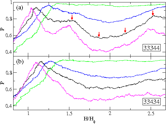
P, the fraction of occupied pins, vs H/Hϕ. (a) The 3342 array at Fp = 0.2, 0.3, 0.5, and 0.8, from bottom right to top right. Arrows pointing to various locations on the Fp=0.3 curve indicate field levels where we show the corresponding real-space vortex configurations in figure 7. (b) The 32434 array at Fp=0.2, 0.3, 0.5, and 0.8, from bottom right to top right.

3.1.2  Pinning occupancy

Another metric which captures features of the vortex states not apparent in magnetization measurements is the fraction of occupied pinning sites P, which we plot as a function of H/Hϕ for both array types in figure 6. For field levels somewhat above first matching field H/Hϕ=1.0, vortices tend to freely enter the sample through the gaps between pins. Since the magnetization M is a measure of the resistance of the sample to flux entry, figure 3 shows that M is small and relatively featureless except at special field values such as H/Hϕ=1.5 or 2.5 where an ordered state forms that collectively resists vortex entry. In contrast, the pinning occupancy P provides more detailed information about the vortex configurations.
There is a peak in P just above H/Hϕ = 1.0 corresponding to the first matching field where most of the pinning sites are occupied. This peak shifts to larger H/Hϕ as Fp increases since the pins at the edges of the sample are the first to be occupied, and for large enough Fp they are able to cage and trap interstitial vortices before the pins at the center of the sample become occupied. For weaker pinning, Fp ≤ 0.5, P peaks near H/Hϕ=1.0 but then decreases with increasing field, reaching another plateau or peak value near H/Hϕ = 1.5, as illustrated for Fp=0.3 in figure 6(a). As H/Hϕ increases further, P drops substantially when vortices start to push their way into triangular plaquettes, causing the vortices at the neighboring pinning sites to depin. Near H/Hϕ=2.0, P passes through a minimum; the overall vortex configuration at H/Hϕ = 2.0 is disordered and there is no peak in M at this field. At H/Hϕ = 2.0 the system could in principle form an ordered state intermediate to the ideal H/Hϕ=1.5 and 2.5 states, with all of the square plaquettes occupied as well as every other triangular plaquette; however, this state does not form. Instead, we find that as the field is increased from the ordered H/Hϕ = 1.5 state where only the square plaquettes are occupied, some pinned vortices are pushed out of the pinning sites when additional vortices occupy the triangular plaquettes. As a result, the pin occupancy actually decreases with increasing field, as shown in figure 6(a). Above H/Hϕ=1.5, P recovers and increases to a peak at the ordered H/Hϕ = 2.5 state, where every square and every triangular plaquette contains an interstitial vortex as illustrated in figure 5(d,e). The field level for this state can be understood from figure 2(a), where we see that a basis for the 3342 tiling has 2 pinning sites, 2 triangular plaquettes, and 1 square plaquette; if all these are singly occupied, we obtain a field level of 5/2 = 2.5.
Fig7.png
Figure 7: Real space images of vortex configurations for the 3342 array at Fp=0.3 as the field H/Hϕ is increased from 1.5 to 2.5, showing lines of interstitial vortices buckling and then reforming. Open circles: pinning sites; filled dots: vortices; thick lines: guides to the eye running along rows of plaquettes and connecting their centers, which are preferred locations for interstitial vortices when all surrounding pinning sites are occupied. (a) H/Hϕ = 1.535; (b) 1.865; (c) 2.185; (d) 2.524. The field levels shown correspond to the red arrows in figure 6(a).
In figure 7 we visualize the transition from H/Hϕ = 1.5 to H/Hϕ = 2.5 in real space for weak pinning Fp=0.3. After the first matching field is reached and the pinning sites become occupied, interstitial vortices enter the sample between the square tiles in neat horizontal lines. This continues until every square tile in a row contains one interstitial vortex, giving the H/Hϕ=1.5 state shown in figure 7(a). When further vortices attempt to enter, the lines of interstitials buckle, as shown in figure 7(b,c); in this process, many pinned vortices are dislodged, and the triangular plaquettes become filled in an irregular manner. As the sample approaches the ordered H/Hϕ=2.5 state, the lines of interstitial vortices re-form along the square plaquettes, and the triangular plaquettes now also fill with lines of interstitials which zig-zag due to the alternating orientation of the triangles. This is illustrated in figure 7(d).
For stronger pinning Fp > 0.5, the pinned vortices do not depin when the triangular plaquettes start to become occupied around H/Hϕ=2.0, as shown for Fp=0.8 in figure 6(a); thus, the buckling phenomenon observed for weaker pinning does not occur in this case. However, the vortex configurations around H/Hϕ=2.0 are still disordered even for strong pinning, as the triangles do not fill in an orderly manner.
Fig8.png
Figure 8: (a) P4, the fraction of vortices with a coordination number of 4, vs H/Hϕ for the 3342 array in a system with np = 2.0/λ2 and Fp = 0.2 (blue), 0.5 (red) and 1.0 (green). Here a peak (marked with an arrow) occurs near H/Hϕ = 0.5 for the weakest pinning. (b) P4 vs H/Hϕ for the 32434 array at np=2.0/λ2 and Fp = 0.2 (blue), 0.5 (red) and 1.0 (green); the peak from panel (a) is absent. (c) A subsection of the Fp = 0.2 system in the 3342 sample from panel (a) at H/Hϕ=0.5. Empty circles: unoccupied pinning sites; filled circles: occupied pinning sites; white squares and triangles: unoccupied square and triangular plaquettes; filled squares and triangles: square and triangular plaquettes that each contain one vortex. A thick heavy line is drawn between pairs of occupied pinning sites to highlight the herringbone ordering.

3.2  Submatching states

We also find vortex ordering at some submatching fields for the 3342 pinning array. This is more clearly visible in an array with higher density np = 2.0/λ2 and small Fp. In figure 8(a) we plot P4, the fraction of vortices with a coordination number of four, versus H/Hϕ for samples with 3342 pinning arrays with Fp=1.0, 0.5, and 0.2. We obtain the coordination number zi of each vortex using a Voronoi construction of the vortex positions, and take Pn=Nv−1i=1Nvδ(nzi). For Fp = 0.2 there is a peak in P4 just above H/Hϕ = 0.5, marked with an arrow in figure 8(a), which corresponds to an ordered vortex sub-matching configuration. This configuration is illustrated in figure 8(c), where we show the locations of the vortices and pinning sites and add a thick line between pairs of occupied pinning sites to make the ordering more visible. Here, every other pinning site captures a vortex and there is an effective dimerization of the occupied pinning sites along the edges of the triangular plaquettes. The dimers are tilted 30° from the y axis in one row and −30° from the y axis in the next row, giving a herringbone ordering of the type previously studied for dimer molecules adsorbed on triangular substrates [34]. As the pinning strength increases, the dimer ordering disappears when the vortex-vortex repulsion is no longer strong enough to maintain empty pins in between dimers; these simply fill once a vortex encounters them. For the 32434 array there is no herringbone ordering, as shown by the absence of a peak in P4 in figure 8(b).
Fig9.png
Figure 9: M vs H/Hϕ for the 32434 array from figure 1(c) for np=1.0/λ2. (a) Fp = 0.1 (black), 0.2 (red), and 0.3 (green). (b) The same for Fp = 0.5 (blue), 0.8 (cyan) and 1.0 (violet).

4  Snub Square (32434) Tiling

We next consider the the snub square tilling or 32434 pinning array illustrated in figure 1(c). In figure 9(a) we plot M vs H/Hϕ for this array with Fp = 0.1, 0.2, and 0.3, while samples with Fp=0.5, 0.8, and 1.0 are shown in figure 9(b). Here a matching peak occurs at H/Hϕ = 1.0 but there are no other clearly defined peaks at the higher fillings. For the stronger pinning sample with Fp=1.0, the first matching peak is obscured by the initial rise of M as shown in figure 9(b). Since there are few additional features in M, we use alternative measurements to show that a variety of partially ordered vortex states can occur in this system. In particular, we consider the fraction of n-fold coordinated vortices Pn, with n=4, 5, 6, 7, and 8.
Fig10.png
Figure 10: Pn vs H/Hϕ for the 32434 array at Fp = 1.0, with P4 (red), P5 (green), P6 (blue), P7 (violet) and P8 (cyan). (a) All vortices in the system. (b) Pinned vortices only. (c) Unpinned vortices only. Below H/Hϕ=1.25 (blank region in panel (c)), there are too few unpinned vortices to give a clear signal.
Fig11.png
Figure 11: Plaquette occupancy in representative strips of the samples for the 32434 array with Fp=1.0, at field levels corresponding to peaks in figure 10(c). The full width of the pinned region is shown. The coloring scheme is illustrated in figure 4. (a) H/Hϕ = 1.65, (b) 1.79, (c) 2.08, (d) 2.33, and (e) 2.56.
In figure 10(a) we plot Pn with n=4 through 8 versus H/Hϕ for all the vortices in a 32434 sample with strong pinning Fp = 1.0. The ordered states in this system can be more easily distinguished by separately measuring Pn for the pinned vortices only, shown in figure 10(b), and for the interstitial or unpinned vortices only, shown in figure 10(c). In particular, in figure 10(c) we find successive peaks in P4,5,6,7,8 for the interstitial vortices. Since there are few to no interstitial vortices for H/Hϕ < 1.25, we do not show Pn for this field range in figure 10(c). The first peak in Pn for the interstitial vortices appears in P4 just above H/Hϕ = 1.5 in figure 10(c). Here, most of the pinning sites are occupied and the interstitial vortices primarily sit in the square plaquettes, as indicated in the plaquette occupancy plot in figure 11(a) for H/Hϕ = 1.65. An interstitial vortex in a square plaquette has four nearest neighbors, which are the pinned vortices at the edges of the plaquette. As the field increases, interstitial vortices begin to occupy isolated triangular plaquettes, providing an additional nearest neighbor for the interstitial vortices in the nearby square plaquettes. This produces a peak in P5 at H/Hϕ = 1.79 in figure 10(c), where nearly all of the filled square plaquettes have one neighboring filled triangular plaquette as shown in figure 11(b). At H/Hϕ = 2.08, there is a peak in P6 in figure 10(c), and the corresponding configuration in figure 11(c) shows that many of the square plaquettes now have two neighboring filled triangular plaquettes. A peak in P7 appears at H/Hϕ = 2.33 in figure 10(c), and the configuration in figure 11(d) has many square plaquettes with three neighboring filled triangular plaquettes, as well as a few doubly occupied square plaquettes. Finally, at H/Hϕ = 2.56 there is a peak in P8 in figure 10(c). The corresponding configurations in figure 11(e) indicate that most of the plaquettes are now filled, with some empty triangular plaquettes and some doubly occupied square plaquettes.
We can understand the field levels at which the peaks in Pn occur by referring to figure 2(b), where we illustrate both the pinning site basis and the plaquette basis which generate the 32434 tiling. In a ground state configuration at H/Hϕ = 1.0, there are four vortices occupying the four pins comprising the basis, with no interstitial vortices. For the state where each square plaquette is occupied by one interstitial vortex, there are a total of 6 vortices and 4 pins per basis, so the field for this state is H/Hϕ = 6/4 = 1.5. Each of the interstitial vortices sitting in a square plaquette has 4 nearest neighbors, the pinned vortices at the corners of the square. As H/Hϕ increases further, the triangular plaquettes become occupied one by one, with each new triangular plaquette interstitial providing an additional nearest neighbor for a nearby square plaquette interstitial vortex. This process gives a total of 7, 8, 9, or 10 vortices per basis corresponding to fields of H/Hϕ = 1.75, 2.0, 2.25, and 2.5, respectively. Thus, the peaks in P4, P5, P6, P7, and P8 for the unpinned vortices in figure 10(c) arise simply from the coordination numbers of the interstitial vortices occupying the square plaquettes. The actual peaks from the simulation shown in figure 10(c) occur at H/Hϕ = 1.65, 1.79, 2.08, 2.33, and 2.56, which are close to the ideal field values. The small shift in the actual values is due to the flux gradient and also to the occasional double occupancy of square plaquettes found in figure 11(d,e). The peaks in Pn for the pinned vortices shown in figure 10(b) follow immediately from the behavior of the interstitial vortices described above. We note in particular that P5 becomes nearly one at H/Hϕ = 2.5, since almost all the triangular and square plaquettes are occupied as shown in figure 11(e). Since each pinning site is surrounded by 5 plaquettes, the nearest neighbors of each pinned vortex are surrounded by 5 interstitial vortices at this filling.

5  Smaller Pinning Densities

Fig12.png
Figure 12: M vs H/Hϕ for samples with np=0.5/λ2 and Fp = 0.3. (a) In the 3342 array, there are additional peaks at H/Hϕ = 3.5 and 4.0. Insets: the ordered vortex arrangements that appear at these additional peaks, indicated by arrows. Open circles: pinning sites; filled circles: vortices. (b) In the 32434 array, there is a peak at H/Hϕ = 3.75; the inset shows the ordered vortex arrangement that forms at this field. Open circles: pinning sites; filled circles: vortices.
For the case of a pinning density of np = 0.5/λ2 and smaller Fp we can readily observe matching peaks up to H/Hϕ = 5.0. In figure 12(a) we plot M vs H/Hϕ for the 3342 array at Fp = 0.3 and in figure 12(b) we show the same quantity for the 32434 pinning array. In the 3342 array, we find the same peaks shown in figure 3 at H/Hϕ = 1.0, 1.5, and 2.5, and we observe additional peaks just below H/Hϕ = 3.5 and 4.0. In the insets of figure 12(a) we plot the vortex and pinning site locations at the two new peaks at H/Hϕ=3.5 and 4.0. Here, all of the pinning sites are occupied and an ordered crystalline arrangement of vortices occurs. By directly counting the number of vortices per pinning site in the ordered part of the sample, we confirm that these are the 3.5 and 4.0 fillings. For the 32434 array, figure 12(b) shows a peak in M for H/Hϕ = 3.75 corresponding to the ordered vortex array illustrated in the inset.

6  Summary

We have investigated ordering and pinning of vortices interacting with Archimedean pinning arrays. The arrays are constructed using the vertices of Archimedean tilings of squares and triangles, and we specifically examine the elongated triangular tiling and the snub square tiling. For the elongated triangular or 3342 array, we find that beyond the first matching field, the interstitial vortices first fill the square plaquettes and subsequently fill the triangular plaquettes, producing pronounced peaks in the magnetization at noninteger matching fields along with an absence of peaks at certain higher integer matching fields. The competition between filling the more confined triangular plaquettes with single vortices or doubly occupying the larger square plaquettes can lead to a decrease in the fraction of occupied pins as the field is increased, and can produce disordered vortex states at certain integer matching fields. We also find novel vortex orderings at submatching fillings, such as herringbone configurations for weak pinning. For the snub square or 32434 array above the first matching field, we find that by analyzing the plaquette fillings we can correctly predict the appearance of a sequence of partially ordered states, where interstitial vortices first occupy square plaquettes and then fill the triangular plaquettes. At higher fields we observe additional commensuration effects at noninteger matching fields which correspond to ordered vortex structures. Our results can be tested for experiments on Archimedean tilling pinning arrays in superconductors as well as for colloids interacting with optical trap arrays with similar geometries.

7  Acknowledgments

This work was carried out under the auspices of the NNSA of the U.S. DoE at LANL under Contract No. DE-AC52-06NA25396.

References

[1]
Fiory A T, Hebard A F and Somekh S 1978 Appl. Phys. Lett. 32 73
[2]
Baert M, Metlushko V V, Jonckheere R, Moshchalkov V V, and Bruynseraede Y 1995 Phys. Rev. Lett. 74 3269
[3]
Metlushko V, Welp U, Crabtree G W, Osgood R, Bader S D, DeLong L E, Zhang Z, Brueck S R J, Ilic B, Chung K and Hesketh P J 1999 Phys. Rev. B 60 R12585
[4]
Martín J I, Vélez M, Nogués J and Schuller I K 1997 Phys. Rev. Lett. 79 1929
[5]
Welp U, Xiao Z L, Jiang J S, Vlasko-Vlasov V K, Bader S D, Crabtree G W, Liang J, Chik H and Xu J M (2002) Phys. Rev. B 66 212507
[6]
Goldberg S, Segev Y, Myasoedov Y, Gutman I, Avraham N, Rappaport M, Zeldov E, Tamegai T, Hicks C W and Moler K A (2009) Phys. Rev. B 79 064523
[7]
Thakur A D, Ooi S, Chockalingam S P, Jesudasan J, Raychaudhuri P and Hirata K (2009) Appl. Phys. Lett. 94 262501
[8]
Swiecicki I, Ulysse C, Wolf T, Bernard R, Bergeal N, Briatico J, Faini G, Lesueur J and Villegas J E (2012) Phys. Rev. B 85 224502
[9]
Harada K, Kamimura O, Kasai H, Matsuda T, Tonomura A and V.V. Moshchalkov V V (1996) Science 274 1167
[10]
Reichhardt C, Olson C J and Nori F (1998) Phys. Rev. B 57 7937
[11]
Berdiyorov G R, Milosevic M V and Peeters F M (2006) Phys. Rev. Lett. 96 207001
[12]
Karapetrov G, Fedor J, Iavarone M, Rosenmann D and Kwok W-K (2005) Phys. Rev. Lett. 95 167002
[13]
Baert M, Metlushko V V, Jonckheere R, Moshchalkov V V and Bruynseraede Y (1995) Europhys. Lett. 29 157
[14]
Reichhardt C and Grønbech-Jensen N (2001) Phys. Rev. B 63 054510
[15]
Field S B, James S S, Barentine J, Metlushko V, Crabtree G, Shtrikman H, Ilic B and Brueck S R J (2002) Phys. Rev. Lett. 88 067003
[16]
Grigorenko A N, Bending S J, Van Bael M J, Lange M, Moshchalkov V V, Fangohr H and de Groot P A J (2003) Phys. Rev. Lett. 90 237001
[17]
Ooi S, Mochiku T and Hirata K (2009) Physica C 469 1113
[18]
Martín J I, Vélez M, Hoffmann A, Schuller I K and Vicent J L (1999) Phys. Rev. Lett. 83 1022
[19]
Reichhardt C, Zimányi G T and Grønbech-Jensen N (2001) Phys. Rev. B 64 014501
[20]
Morgan D J and Ketterson J B (1998) Phys. Rev. Lett. 80 3614
[21]
Wu T C, Wang J C, Horng L, Wu J C and Yang T J (2005) J. Appl. Phys. 97 10B102
[22]
Reichhardt C and Olson Reichhardt C J (2007) Phys. Rev. B 76 064523
[23]
Cao R, Horng L, Wu T C, Wu J C and Yang T J (2009) J. Phys.: Condens. Matter 21 075705
[24]
Latimer M L, Berdiyorov G R, Xiao Z L, Kwok W K and Peeters F M (2012) Phys. Rev. B 85 012505
[25]
Reichhardt C and Olson Reichhardt C J (2007) Phys. Rev. B 76 094512
[26]
Kemmler M, Bothner D, Ilin K, Siegel M, Kleiner R and Koelle D (2009) Phys. Rev. B 79 184509
[27]
Libál A, Olson Reichhardt C J and Reichhardt C (2009) Phys. Rev. Lett. 102 237004
[28]
Silhanek A V, Van Look L, Jonckheere R, Zhu B Y, Raedts S and Moshchalkov V V (2005) Phys. Rev. B 72 014507
[29]
Horng L, Cao R, Wu T-C, Yang S, Wang S-H, Wu J-C and Yang T-J (2013) J. Appl. Phys. 113 17E118
[30]
Ray C, Reichhardt C and Olson Reichhardt C J, unpublished.
[31]
Reichhardt C, Olson C J, Groth J, Field S and Nori F (1995) Phys. Rev. B 52 10441
[32]
Reichhardt C, Groth J, Olson C J, Field S B and Nori F (1996) Phys. Rev. B 54 16108
[33]
Ray D, Olson Reichhardt C J, Jankó B and Reichhardt C (2013) Phys. Rev. Lett. 110 267001
[34]
Nicol E J, Kallin C and Berlinsky A J (1988) Phys. Rev. B 38 556
[35]
Grünbaum B and Shephard G C Tilings and Patterns (W.H.Freeman, New York, 1987), Ch. 2.
[36]
Bean C P (1962) Phys. Rev. Lett. 8 250; (1964) Rev. Mod. Phys. 36 31


File translated from TEX by TTHgold, version 4.00.
Back to Home