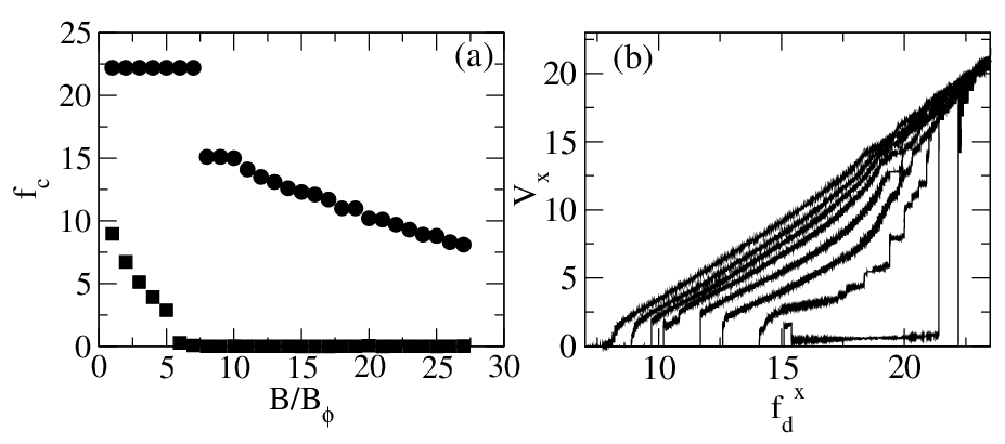
Physical Review B 73, 184519 (2006)

Vortex configurations and dynamics in elliptical pinning sites for high matching fields

C.J. Olson Reichhardt1, A. Libál1,2, and C. Reichhardt1

1Theoretical Division and Center for Nonlinear Studies, Los Alamos National Laboratory, Los Alamos, New Mexico 87545, USA
2Department of Physics, University of Notre Dame, Notre Dame, Indiana 46556, USA

(Received 31 December 2005; revised manuscript received 27 March 2006; published 17 May 2006)

Using numerical simulations we study the configurations, dynamics, and thermal depinning properties of vortex lattices interacting with elliptical pinning sites at integer matching fields with as many as 27 vortices per pin. Our pinning model is based on a recently produced experimental system [G. Karapetrov et al., Phys. Rev. Lett. 95, 167002 (2005)], and the vortex configurations we obtain match well with experimental vortex images from the same system. We find that the strong pinning sites capture more than one vortex each, and that the saturation number of vortices residing in a pin increases with applied field due to the pressure from the surrounding vortices. At high matching fields, the vortices in the interstitial regions form a disordered triangular lattice. We measure the depinning thresholds for both the x and y directions, and find distinctive dynamical responses along with highly anisotropic thresholds. For thermal depinning of the vortex configurations under zero applied current, we find multi-step thermal depinning transitions in which the interstitial vortices begin to diffuse at a much lower temperature than the pinned vortices. We associate this with signatures in the specific heat.
I. INTRODUCTION
II. SIMULATION
III. MATCHING FIELDS
IV. TRANSPORT
A. x direction depinning
B. y direction depinning
V. THERMAL EFFECTS
A. Diffusion and thermal depinning
B. Specific heat
VI. CONCLUSION
References


I.  INTRODUCTION

The immobilization of superconducting vortices at pinning sites is a critical area of study for device applications, since the dissipation that occurs when the vortices move under an applied current sets a limitation on the effectiveness of the superconductors for lossless transport. Any superconductor contains naturally occurring pinning which may take the form of nonsuperconducting inclusions, twin boundaries, or other types of defects. Over the past few decades, there has been a tremendous amount of progress in the fabrication of artificial nanoengineered pinning, and particularly lattices of pins. Due to the possibility of commensuration effects between the vortex lattice and the pinning lattice, the artificial pinning can be tremendously more effective at immobilizing the vortices and enhancing the maximum critical current than the naturally occurring disorder in a sample. Significant effort has been focused on developing and studying different types of periodic pinning, beginning with one-dimensional pinning created through thickness modulation of the superconducting film [1]. This was soon followed by the fabrication of two-dimensional arrays of holes [2,3,4,5].
Large holes can confine more than one flux quantum each [6,7]. Multiple vortices inside a single hole coalesce into a single multiquanta vortex, since there is no superconducting material to support distinct cores for each vortex. In contrast, in blind holes, which do not pass completely through the superconducting material, individual vortex cores retain their identity within the hole. Multiple occupation by single quantum vortices in large blind holes was imaged experimentally using a Bitter decoration technique [8] and later studied in simulation [9].
Continuing advances in nanolithography focused attention on the production of small, closely spaced holes that could each capture a single vortex. Combined with this, significant advances in imaging techniques have contributed to our understanding of the interaction between vortices and the periodic pinning. In particular, if the applied magnetic field exceeds the matching field at which the number of vortices present equals the number of pinning sites, then in the case of small holes, the extra vortices above the matching field cannot occupy the holes but must instead sit at interstitial locations in the superconducting material surrounding the holes. These interstitial vortices are weakly pinned via the repulsion from vortices trapped at pinning sites, and their configurations have been imaged using electron-beam microscopy techniques [10], scanning Hall probe microscopy [11,12,13] and scanning μSQUID devices [14]. The interstitial vortex arrangements are sensitive to the structure of the periodic pinning, and a wide range of different types of artificial pinning lattices have been tested experimentally [15,16,17,18], including both symmetric pinning arrays as well as asymmetric arrays such as rectangular arrangements of holes [19,20]. The weak pinning of the interstitial vortices can produce asymmetric critical currents [21,22,23,24].
Simulations of vortices in periodic arrays of singly occupied pins give good agreement with experimental observations and indicate the importance of the interstitial vortices in determining the dynamical response of the system [25,26,27,28]. This is particularly important in understanding the field dependence of the behavior of nanopatterned superconductors. Vortices are strongly pinned at the matching field when the number of vortices equals the number of artificial pins, but the effectiveness of the pinning is dramatically reduced whenever defects in the form of interstitials or vacancies are introduced by shifting the applied field away from its matching value. The result is experimentally observable as oscillations in critical current [29] or resistivity [30,31,32], as well as through separate depinning transitions for interstitial vortices [33,34,35,36]. Due to the fact that the pinning of interstitial vortices is weak, pins which capture multiple vortices are much more effective at increasing the critical current over a wider range of field [37]. There is, however, a trade off between saturation number of the pin and size of the nanoarrays; for example, in an imaging experiment for relatively large dots, as many as 280 vortices were captured by each artificial pin [38].
In the interest of combining small size with greater pinning effectiveness, recent work has shifted away from simple circular holes or antidots to asymmetric pinning sites. Asymmetry can be introduced by placing symmetric pins in asymmetric unit cells containing two pins each [39,40]; alternatively, the pins themselves may be made into asymmetric shapes, such as triangles [41,42] or rectangles [43]. Arrangements of rectangular pins are of particular interest since they may be used as the basis for vortex logic devices, in which each elongated pin can hold a single bit of information [44,45].
A new fabrication technique has recently been developed to create well controlled elongated pinning sites in a sample with an atomically flat surface [46,47]. This permits direct imaging of the vortex positions using scanning spectroscopy methods. Due to the extremely high resolution of this imaging technique, vortex configurations can be observed at fields well above matching, showing interesting effects such as the formation of a disordered triangular vortex lattice in the region between pinning sites. Obtaining an image with a scanning technique is a time-consuming process, so dynamical information about the vortices is not available from the experiments of Refs. [46,47]. It would be interesting to explore the dynamical behavior of the vortices under applied currents or finite temperatures at high matching fields. Existing simulations have been confined to low matching fields, with studies reaching at most the ninth matching field [27], and higher matching fields have never been considered. The particular pinning geometry used in Ref. [46] also has unique aspects which have not been explored previously.
In this work, we study the static and dynamic behaviors of vortices interacting with elongated pinning sites of the type created in Ref. [46] for matching fields as high as 27 vortices per pinning site. We explore the dynamic response of the vortices to applied currents, and find strongly asymmetric depinning forces. We also study the thermal depinning of the vortex configurations and find interesting two-stage thermal depinning behavior in which the interstitial vortices begin to diffuse at much lower temperatures than the pinned vortices. The particular model of the pinning that we use has not been considered before and gives good agreement with the vortex configurations obtained in experiment. We also study much higher matching fields than have been simulated previously. The dynamic vortex responses that we observe are related to the particular symmetries present at each matching field.

II.  SIMULATION

We model a two-dimensional system of Nv vortices in a superconducting crystal containing Np artificial pinning sites. We assume periodic boundary conditions in the x and y directions. The overdamped equation of motion for an individual vortex i is
η dri

dt
= fivv + fTi + fpi + fdi
(1)
The damping constant η = ϕ02d/2πξ2ρN in a crystal of thickness d. Here, ϕ0=h/2e is the flux quantum, ξ is the superconducting coherence length, and ρN is the normal state resistivity of the material. The vortex-vortex interaction force is
fivv = Nv

ji 
f0K1
rij

λ

^
r
 

ij 
,
(2)
where K1 is the modified Bessel function appropriate for stiff three-dimensional vortex lines. λ is the London penetration depth, f002/(2πμ0λ3), and rij is the distance between vortices i and j. We measure time in units of τ = η/f0. For a NbSe2 crystal 0.1 mm thick, we take η = 2.36×10⁻¹¹ Ns/m, f0=6.78×10⁻⁵ N/m, and τ = 0.35 μs. The thermal force fTi arises from random Langevin kicks with the properties 〈fTi〉 = 0 and 〈fiT(t)fjT(t)〉 = 2ηkBT δ(ttij. The conversion from physical temperature to simulation units is given by
fT= 1

d
  ⎛


kB T

δτ
 
.
(3)
Using δτ = 0.01, a temperature of 4.2K corresponds to fT=4.12×10⁻⁷ f0. Thus, for our measurements of transport characteristics, we take fT=0.
The quenched disorder fip is modeled as composite pinning sites constructed to match the experimental geometry. The sample contains parabolic troughs 0.5λ wide that run in the y direction and are spaced 2.5λ apart in the x direction, corresponding to 0.5μm in NbSe2. Each trough is decorated with parabolic traps that confine only in the y direction, which define the locations of the pinning sites shown in the experimental images. These traps are 1.5λ long in the y direction and equal to the trough width in the x direction. The long troughs represent the fact that the crystal layer in Ref. [46] is extremely thin between the pins in the y direction. This produces an energetically favorable location for a vortex. Within the pinning sites, the order parameter is completely suppressed by the gold in the actual experimental sample, and the vortices inside the pinning site would form a macrovortex state which is, however, not circular due to the pinning geometry. In our model, macrovortex formation is not permitted, but the configuration of vortices inside a given pin approximates the noncircular current configuration expected to occur in the experimental geometry. We use pinning strengths of 12.0 for the decorating troughs and 90.0 for the channel. This produces a square array of pinning sites each of which is elongated in the y direction, as illustrated in Fig. 1.
Fig1.png
Figure 1: Vortex configurations at the first nine matching fields. Black dots indicate vortex positions and pinning sites are indicated by ellipses. The pinning troughs connecting the pins in the y direction are indicated by lines in (a) and can be identified in the other panels based on the vortex positions. B/Bϕ= (a) 1, (b) 2, (c) 3, (d) 4, (e) 5, (f) 6, (g) 7, (h) 8, and (i) 9.
The Lorentz driving force from an external applied current is given by fd, which may be applied either in the x direction, fd=fdx, or in the y direction, fd=fdy. We measure the corresponding velocity responses in either x, Vx=(1/Nv)〈∑i=1Nvvi·x〉, or y, Vy=(1/Nv)〈∑i=1Nvvi·y〉. The system size is measured in units of λ and the forces in terms of f0. Most of the results presented here are for a sample of size 10λ×10λ containing Np=16 pins. We consider filling fractions up to B/Bϕ=27, corresponding to 432 vortices. At these fields, even though the vortex-vortex interaction is of a short-range form appropriate for a crystalline sample, many vortices fall within the interaction range of a given vortex, and as a result the simulations become computationally intense. It is for this reason that we consider the sample size illustrated in the figures. We have also tested larger samples of size 30λ×30λ containing 144 pinning sites and find substantially identical results.

III.  MATCHING FIELDS

We first consider the vortex arrangements at integer filling fractions B/Bϕ=Nv/Np. For each field, we initialize the sample at a high temperature so that the vortices are diffusing freely, and then slowly decrease the temperature in order to anneal the system toward the T=0 ground state. Figure 1 illustrates the zero temperature vortex configurations at the first nine matching fields for a sample with Np=16 pinning sites. For B/Bϕ=1 to 4, the vortices are confined fully within the pinning sites and form single lines. At B/Bϕ=5, the pinning confinement is not strong enough to capture a fifth vortex inside the pin, so one vortex per unit cell occupies an interstitial position. If the pinning force existed only within the ellipses drawn in the figure, the interstitial vortex would occupy the low energy point at the same y position located halfway between rows of pins, but it would move over by half a pinning lattice constant in order to sit midway between columns of pinning. This does not happen due to the presence of the additional pinning trough introduced in our model. A similar vortex configuration for one interstitial vortex per unit pinning cell is observed in the experiment due to the nonuniform ion beam patterning of the pinning geometry in the x and y directions, and the configuration in Fig. 1(e) matches well with the configuration shown in Fig. 2(b) of Ref. [46]. At B/Bϕ=6, a second interstitial vortex can not fit inside the pinning trough, so it occupies the next most favorable location centered between four pinning sites. The result is the formation of rows of interstitial vortices, and Fig. 1(f) resembles the configuration shown in Fig. 2(c) of Ref. [46]. At B/Bϕ ≥ 6, we begin to observe some disorder in our vortex configurations, and for B/Bϕ=6, a few of the pins have captured five vortices instead of four. This trend continues at higher fillings: the occupation number of the pins does not saturate but slowly increases as the overall higher vortex density outside the pinning site helps to stabilize a larger number of vortices inside the pinning site. A gradual increase in hole saturation number was also observed in the experiments of Ref. [46]. At B/Bϕ=7 the interstitial vortices begin to spread out into the free channel between columns of pinning sites, and this continues at B/Bϕ=8, where all pins now capture five vortices. The interstitial vortex channels in Fig. 1(h) match well with Fig. 2(d) of Ref. [46]. By B/Bϕ=9, some defects occur in the interstitial channels and the vortices start to buckle out along the space between pinning rows in order to form a second interstitial column. Figure 1(i) is in good agreement with the configuration obtained in Fig. 3(a) of Ref. [46].
Fig2.png
Figure 2: Vortex configurations at the second nine matching fields. Black dots indicate vortex positions and pinning sites are indicated by ellipses. B/Bϕ= (a) 10, (b) 11, (c) 12, (d) 13, (e) 14, (f) 15, (g) 16, (h) 17, and (i) 18.
Fig3.png
Figure 3: Vortex configurations at the third nine matching fields. Black dots indicate vortex positions and pinning sites are indicated by ellipses. B/Bϕ= (a) 19, (b) 20, (c) 21, (d) 22, (e) 23, (f) 24, (g) 25, (h) 26, and (i) 27.
Fig4.png
Figure 4: 
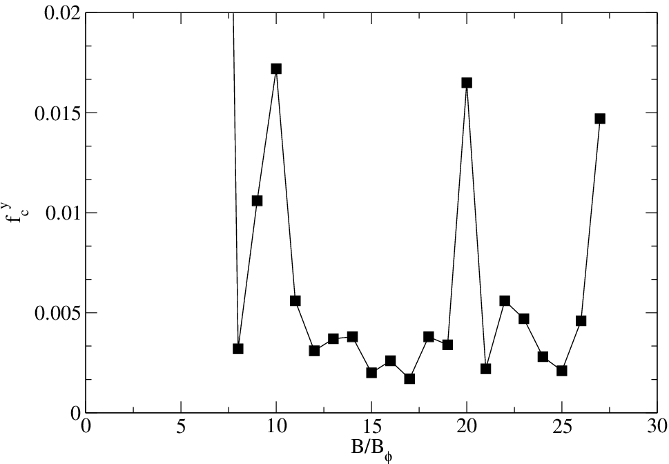
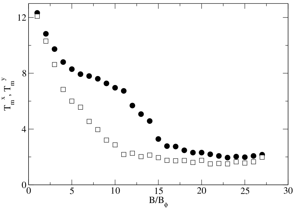
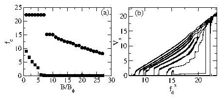
(a) The critical depinning force for two different driving directions at matching fields B/Bϕ=1 to 27. Circles: fcx for driving in the x direction; squares: fcy for driving in the y direction. (b) Representative velocity-force curves for x-direction driving, Vx versus fdx, for B/Bϕ= (from right to left) 1, 9, 11, 14, 17, 20, 22, 24, and 27.
Vortex configurations at the second nine matching fields, B/Bϕ=10 to 18, are illustrated in Fig. 2. For B/Bϕ=10 and 11, we find a gradual buckling transition of the columns of interstitial vortices filling the vertical gaps between the pins. The vortex configuration in the columns gradually changes from one vortex wide at B/Bϕ=10 in Fig. 2(a) to two vortices wide by B/Bϕ=15 in Fig. 2(f). At B/Bϕ=16 in Fig. 2(g) we obtain a configuration that agrees well with Fig. 3(b) of Ref. [46]. The buckling transition begins anew as the field is further increased, and by B/Bϕ=18 in Fig. 2(i) portions of the interstitial channels contain a vortex arrangement three vortices wide. The pinning sites continue to capture larger numbers of vortices as the field increases, and at B/Bϕ=15 and above these configurations also begin to buckle inside the pinning sites. The small portion of the pinning channel between the pins in the y direction also captures more than one vortex starting at B/Bϕ=13.
We illustrate vortex configurations at matching fields much higher than have been simulated previously, through B/Bϕ=27, in Fig. 3. Vortices continue to populate the interstitial region of the channels as the field is further increased, and the vortex occupation number of the pins and of the small trough region connecting the pins continues to slowly increase with B/Bϕ. We do not find perfectly parallel rows of vortices as was indicated schematically in Fig. 3(c) of Ref. [46], but instead observe a marked modulation of the vortex density inside the channel caused by the strong repulsion from the large number of vortices confined within each elongated pin. This is in general agreement with the actual image in Fig. 3(c) of Ref. [46], which compares well with our Fig. 3(e) at B/Bϕ=23. There is still a tendency for the interstitial vortices to form rows parallel with the x axis and passing between pinning rows, which is particularly pronounced at B/Bϕ=20 in Fig. 3(b) and to a lesser degree at B/Bϕ=22 in Fig. 3(c). As we will show below, this row structure affects the depinning properties of the vortex lattice.

IV.  TRANSPORT

We next study the transport properties of the different fillings by applying a transport current in either the x or y direction. Due to the strong anisotropy of the pinning geometry, we find strongly anisotropic depinning thresholds fcx in the x direction and fcy in the y direction. Figure 4(b) illustrates the depinning force at the matching fields for fd=fdx and fd=fdy. The depinning force in the y direction fcy is much smaller than fcx at all matching fields, and fcy drops nearly to zero above B/Bϕ=5 once interstitial vortices begin to appear in the free channel region between the pins. At incommensurate fields, not shown, we expect the depinning force for both x and y directions to be lower than it is at the commensurate fields.

A.  x direction depinning

We find a nearly constant fcx for B/Bϕ ≤ 7, while for B/Bϕ ≥ 8, fcx gradually decreases with B/Bϕ. Representative velocity-force curves for x direction driving are illustrated in Fig. 4(a). The curves for B/Bϕ= 2 through 7 are essentially identical to the curve shown for B/Bϕ=1, with a sharp depinning transition at fdx=22.2 followed by an ohmic response. The transition in fcx at B/Bϕ ≥ 8 occurs due to a change in the depinning mechanism. For B/Bϕ ≤ 7, vortices initially accumulate inside the pins and the pinning troughs upon application of a driving force, as illustrated in Fig. 5(a) for B/Bϕ=7. Depinning occurs when the pinning force of the pinning troughs in the x direction is overcome. When B/Bϕ ≥ 8, not all of the vortices can fit in a single column inside the trough because the confining force of the pinning troughs is insufficient to overcome the vortex-vortex repulsion. Instead, the vortex column buckles in the trough area between pins, as illustrated in Fig. 5(b) for B/Bϕ=9. Depinning initiates at the buckled points, where the vortex-vortex repulsive force is now added to the driving force on a buckled vortex; as a result, the depinning threshold is considerably lower than for B/Bϕ < 8 and decreases with increasing field. At higher fields the buckling in the vortex configurations below depinning shifts from outside the pins to inside the pins, as shown in Fig. 5(c) for B/Bϕ=11, and eventually buckling occurs in both locations, as illustrated in Fig. 5(d) for B/Bϕ=17. At higher fields, all of the vortices are no longer able to fit inside the pinning trough before the depinning threshold is reached, and instead the interstitial vortices pile up against the repulsive barrier formed by the vortices inside the pinning trough, as shown in Fig. 5(e) and (f) for B/Bϕ= 20 and 27. In this regime, the pinning resembles extremely strong twinning barriers.
Fig5.png
Figure 5: Illustration of the vortex configurations just before depinning under application of a driving force in the x direction (to the right in the figure). Black dots indicate vortex positions and pinning sites are indicated by ellipses; the pinning troughs between the pins running in the y direction are not directly indicated in the figure. B/Bϕ= (a) 7, (b) 9, (c) 11, (d) 17, (e) 20, and (f) 27.
At B/Bϕ=9, close to the transition where the initial buckling of the vortex configuration before depinning shifts from the location between the pins to within the pins, we observe a negative dV/dI characteristic as indicated in Fig. 4(a) around fdx=16. Here, after depinning the vortices initially flow between the rows of pinning sites at the location of the buckled points, but as the drive increases, the flow location shifts and the moving vortices instead pass directly through the pinning sites while the vortices in the troughs between the pinning sites remain pinned. At higher drives there is a step up in Vx at the point when all of the vortices depin. This feature is similar to the dynamic phases observed for symmetric periodic pins in Ref. [26]. For fields above B/Bϕ=9, depinning initiates at the pinning sites and not in the troughs between pins. The initial vortex motion passes through the pinning sites, and the vortices in the troughs between pins do not depin until higher drives are applied. At fields of B/Bϕ=17 and higher, when interstitial vortices are always present even just below the depinning transition, the depinning gradually becomes more elastic with increasing field, as indicated by the gradual rounding of the velocity force curves at depinning in Fig. 5.
Fig6.png
Figure 6: Critical depinning force fcy at higher fillings B/Bϕ ≥ 8. The y axis of the figure has been magnified relative to Fig. 4.
Fig7.png
Figure 7: Illustration of the vortex motion just after depinning under application of a driving force in the y direction (to the top in the figure). Black dots indicate vortex positions, pinning sites are indicated by ellipses, and lines indicate trajectories followed by the vortices over a period of time. B/Bϕ= (a) 8, (b) 10, (c) 19, (d) 20, (e) 21, and (f) 27.

B.  y direction depinning

Depinning in the y direction occurs at much lower applied driving forces than depinning in the x direction. In addition, when we zoom in on the small driving force regime, shown in Fig. 6, we observe a nonmonotonic dependence of fcy on field that is caused by differences in the vortex configurations. At fillings B/Bϕ > 7, the y direction depinning forces are similar in scale to the vortex-vortex interaction forces, permitting the system to be sensitive to vortex configuration changes. This is in contrast to the case for x direction depinning where the extremely strong pinning forces dominate the response of the system. The y direction depinning force fcy is enhanced for B/Bϕ=10, 20, and 27, as indicated in Fig. 6. To understand the origin of this enhancement, we plot the vortex trajectories at driving forces just above depinning for representative fields in Fig. 7. At B/Bϕ=8 in Fig. 7(a), the vortices in the interstitial channels form straight columns and can flow directly in the y direction upon depinning. For B/Bϕ=10, the buckling of the interstitial vortex channels into the spaces between the pinning rows disrupts the straight interstitial columns of vortices, and the vortex paths upon depinning in the y direction wind irregularly. A higher driving force must be applied to produce flow through winding channels compared to the straight channels, since depinning can no longer occur via simple propagation of a solitonlike vortex pulse.
As the number of vortices inside the interstitial channel increases, more than one channel of flow can open, as illustrated in Fig. 7(c) for B/Bϕ=19. This multiple channel flow occurs relatively easily and is associated with a low value of fcy. At B/Bϕ=20, where we observed well formed rows of vortices parallel to the x axis in Fig. 3(b), the vortex flow is hindered for depinning in the y direction since the initial depinning paths wind back and forth, as shown in Fig. 7(d). Addition of one more vortex per unit cell distorts the rows of vortices parallel to the x axis and permits a smoother channel flow to occur with lower fcy, as illustrated in Fig. 7(e) for B/Bϕ=21. Finally, we observe an increase in fcy at the highest field we studied, B/Bϕ=27. In this case, the columns of vortex motion at depinning do not mix; instead, the interstitial vortices move through five parallel channels, as shown in Fig. 7(f). Two of the channels contain only a single vortex per unit cell, and these two channels help to effectively jam the flow at lower driving forces. The depinning process at higher fillings resembles studies of vortex depinning in smooth channels [48]; however, in the case considered here, the effective width of the channel is strongly modulated due to the presence of the highly filled strong pinning sites.
Fig8.png
Figure 8: Finite time total diffusion Dt as a function of temperature for representative vortex fillings B/Bϕ= (bottom to top) 1, 3, 5, 8, 10, 13, 17, and 22.

V.  THERMAL EFFECTS

A.  Diffusion and thermal depinning

We next consider the thermal depinning properties of the vortex configurations at zero applied driving force. We measure the total diffusion Dt=〈(r(t1)−r(t0))2〉/δt as a function of temperature by calculating the distance traveled by the vortices during a fixed time period δt=t1t0. For a fixed choice of δt, thermal depinning appears as a noticeable change in the slope of Dt with temperature. Figure 8 shows representative Dt vs T curves for several values of B/Bϕ. The thermal depinning temperature decreases monotonically with B/Bϕ.
Due to the strong anisotropy of the pinning structure, the thermal depinning occurs anisotropically. To measure this, we compute the diffusion in the x and y directions separately, Dx=〈(rx(t1)−rx(t0))2〉/δt and Dy=〈(ry(t1)−ry(t0))2〉/δt. We show representative plots of Dx and Dy for six values of B/Bϕ in Fig. 9. At B/Bϕ=1, in Fig. 9(a), the vortices remain confined within the pins for T < 10, but since the pins are more extended in the y direction than in the x direction, Dy is larger than Dx at low temperatures, indicating that the vortices undergo larger thermal excursions within the pins in the y direction. At B/Bϕ=4, shown in Fig. 9(b), the change of slope in Dy occurs at lower temperatures than the corresponding slope change in Dx. In this case, thermal activation causes a small number of the vortices to jump out of the wells and occupy interstitial sites once T ≈ 6. These vortices remain confined within a particular interstitial channel but are able to diffuse slowly in the y direction from one interstitial site to another, as illustrated in Fig. 10(a). There is no significant x direction diffusion until T ≈ 8, when all of the vortices begin to hop in and out of the pinning sites. When interstitial vortices are present from the beginning, such as at B/Bϕ=7 shown in Fig. 9(c), Dy is significantly larger than Dx over a sizable temperature range. This is indicative of the formation of an interstitial liquid, where vortices diffuse freely in the y direction in one-dimensional channels between the columns of pins, but the x direction vortex diffusion is suppressed. A representative example of the interstitial liquid is plotted in Fig. 10(b) for B/Bϕ=7. A plateau begins to form in Dx for B/Bϕ=10 and above, as illustrated in Fig. 9(d). At these higher fields, the interstitial channel contains more than one column of vortices, and the onset of y direction diffusion within the interstitial channel is accompanied by a fixed amount of x translation due to the formation of ringlike structures in the vortex trajectories, as shown in Fig. 10(c). Dx remains fixed at a constant value while Dy continues to increase with temperature as long as the interstitial liquid exists. Similar behavior occurs for two interstitial vortex channels at B/Bϕ=15, as shown in Fig. 9(e) and Fig. 10(d), as well as for three interstitial vortex channels at B/Bϕ=20, plotted in Fig. 10(e), and for four interstitial vortex channels at B/Bϕ=27, illustrated in Fig. 9(f) and Fig. 10(f).
Fig9.png
Figure 9: Diffusion in x (Dx, bottom curves) and y (Dy, top curves) directions for fillings B/Bϕ= (a) 1, (b) 4, (c) 7, (d) 10, (e) 15, and (f) 27.
Fig10.png
Figure 10: Illustration of vortex motion during the anisotropic thermal depinning process. Ellipses indicate the locations of the pins, black dots represent vortex positions, and lines show the trajectories of the vortices over a fixed period of time. (a) B/Bϕ=4, T=7.05. (b) B/Bϕ=7, T=3.90. (c) B/Bϕ=10, T=2.46. (d) B/Bϕ=15, T=2.34. (e) B/Bϕ=20, T=1.86. (f) B/Bϕ=27, T=2.25.
In Fig. 11 we summarize the behavior of the thermal depinning temperatures in the x and y directions, Tmx and Tmy, as determined from the diffusion. The thermal depinning occurs at high temperatures and is nearly isotropic for B/Bϕ=1, but anisotropy develops rapidly as the field is increased and becomes particularly pronounced once interstitial vortices appear at B/Bϕ=5. The y-direction thermal depinning temperature, Tmy, drops rapidly with field for 5 < B/Bϕ < 10 as the interstitial vortex channel develops, while Tmx changes only slowly with field in this regime. Once the interstitial channels have fully formed and begin to buckle into a configuration that is two or more vortices wide, at B/Bϕ ≥ 10, Tmy levels off and Tmx begins to drop more rapidly as the space between interstitial channel vortices and pinned vortices decreases with field. Above B/Bϕ=15, when the vortex configurations inside the pins begin to buckle, Tmx also levels off at a low value.
Fig11.png
Figure 11: Squares: Thermal depinning temperature in the y direction, Tmy, as measured from Dy. Circles: Thermal depinning temperature in the x direction, Tmx, as measured from Dx.
The thermal depinning process at higher fillings in general proceeds as follows. The first stage is contour depinning, in which the particles diffuse along the columns of pinning and maintain their spacing in columns. Exchange between columns happens at points where the columns are narrow, which generally falls in between pinning sites. As the temperature increases, this channel structure is lost and the system forms a series of liquid channels where all structure is destroyed. The particles inside the pins move freely inside the pins but remain confined. The final stage of thermal depinning occurs when the pinned particles depin and begin to move along the pinning channel at the same time as particles begin to jump in the x direction from the pinning channel into the unpinned channel liquid and vice versa.
Fig12.png
Figure 12: Specific heat Cv for selected fillings B/Bϕ= (a) 2, (b) 5, (c) 9, (d) 11, (e) 14, (f) 16, (g) 20, (h) 25, and (i) 27.

B.  Specific heat

The multiple stages of thermal depinning in the two directions also appear as signatures in the specific heat,
Cv(T)=(〈E(T)2〉− 〈E(T) 〉2)/T2
(4)
obtained from the average energy of the system E(T). To measure Cv, we begin with a T=0 vortex configuration obtained from a slow anneal. We then gradually increase the temperature in increments of ∆T. At each temperature we compute the average energy of the system, E, and average E(T) over 20 to 600 realizations per filling fraction. We performed the largest number of realizations for small values of B/Bϕ. We obtain the specific heat Cv by taking the derivative of E(T). The resulting curves Cv(T) are illustrated for selected fillings in Fig. 12. For B/Bϕ < 5, thermal depinning occurs when the vortices are thermally activated out of the pinning sites. This produces a single step up in Cv at relatively high temperatures near T  ∼ 10, as illustrated in Fig. 12(a) for B/Bϕ=2. Once interstitial vortices appear, as in Fig. 12(b) for B/Bϕ=5, a new signature appears in Cv at a lower temperature T ∼ 6, corresponding to the temperature at which when the interstitial vortices begin to diffuse and form an anisotropic interstitial liquid. The magnitude of this second peak in Cv varies with filling, as shown in Fig. 12(d) through (i), and the peak shifts to lower temperature as B/Bϕ increases, consistent with the decreasing thermal depinning temperature shown in Fig. 11. Due to the presence of the pinning, all of the thermal depinning transitions in this system should be thermally activated crossovers.

VI.  CONCLUSION

In summary, we used numerical simulations to study the configurations, dynamics, and thermal depinning properties of vortex lattices interacting with elliptical pinning sites for both low and high matching fields. The configurations we obtain agree well with experimental vortex images from the system we are modeling, and as in the experiment we find that the saturation vortex number of the individual pins increases with applied field. The depinning thresholds are highly anisotropic, particularly at higher fields, and the vortex configurations upon depinning are very different depending on whether the current is applied along or perpendicular to the pinning channels. The depinning threshold in the x direction occurs at large driving forces and decreases monotonically with B/Bϕ, while the depinning threshold in the y direction occurs at low driving forces and shows nonmonotonic behavior in response to the vortex configurations at each field. We find anisotropic diffusion when the system thermally depins, along with a second structure in the specific heat corresponding to the presence of an anisotropic interstitial vortex liquid at intermediate temperatures.

7  Acknowledgments

We thank G. Karapetrov for useful discussions. This work was supported by the U.S. Department of Energy under Contract No. W-7405-ENG-36.

References

[1]
O. Daldini, P. Martinoli, J.L. Olsen, and G. Berner, Phys. Rev. Lett. 32, 218 (1974).
[2]
A.F. Hebard, A.T. Fiory, and S. Somekh, IEEE Trans. Magn. MAG-13, 589 (1977).
[3]
A.T. Fiory, A.F. Hebard, and S. Somekh, Appl. Phys. Lett. 32, 73 (1978).
[4]
V.V. Metlushko, M. Baert, R. Jonckheere, V.V. Moshchalkov, and Y. Bruynseraede, Solid State Commun. 91, 331 (1994).
[5]
M. Baert, V.V. Metlushko, R. Jonckheere, V.V. Moshchalkov, and Y. Bruynseraede, Phys. Rev. Lett. 74, 3269 (1995).
[6]
V.V. Moshchalkov, M. Baert, V.V. Metlushko, E. Rosseel, M.J. Van Bael, K. Temst, R. Jonckheere, and Y. Bruynseraede, Phys. Rev. B 54, 7385 (1996).
[7]
V.V. Moshchalkov, M. Baert, V.V. Metlushko, E. Rosseel, M.J. Van Bael, K. Temst, Y. Bruynseraede, and R. Jonckheere, Phys. Rev. B 57, 3615 (1998).
[8]
A. Bezryadin, Yu.N. Ovchinnikov, and B. Pannetier, Phys. Rev. B 53, 8553 (1996).
[9]
C. Reichhardt and N. Grønbech-Jensen, Phys. Rev. Lett. 85, 2372 (2000).
[10]
K. Harada, O. Kamimura, H. Kasai, T. Matsuda, A. Tonomura, and V.V. Moshchalkov, Science 274, 1167 (1996).
[11]
A.N. Grigorenko, G.D. Howells, S.J. Bending, J. Bekaert, M.J. Van Bael, L. Van Look, V.V. Moshchalkov, Y. Bruynseraede, G. Borghs, I.I. Kaya, and R.A. Stradling, Phys. Rev. B 63, 052504 (2001).
[12]
M.J. Van Bael, J. Bekaert, K. Temst, L. Van Look, V.V. Moshchalkov, Y. Bruynseraede, G.D. Howells, A.N. Grigorenko, S.J. Bending, and G. Borghs, Phys. Rev. Lett. 86, 155 (2001).
[13]
S.B. Field, S.S. James, J. Barentine, V. Metlushko, G. Crabtree, H. Shtrikman, B. Ilic, and S.R.J. Brueck, Phys. Rev. Lett. 88, 067003 (2002).
[14]
C. Veauvy, K. Hasselbach, and D. Mailly, Phys. Rev. B 70, 214513 (2004).
[15]
J.-Y. Lin, M. Gurvitch, S.K. Tolpygo, A. Bourdillon, S.Y. Hou, and J.M. Phillips, Phys. Rev. B 54, R12717 (1996).
[16]
D.J. Morgan and J.B. Ketterson, Phys. Rev. Lett. 80, 3614 (1998).
[17]
M.J. Van Bael, L. Van Look, K. Temst, M. Lange, J. Bekaert, U. May, G. Güntherodt, V.V. Moshchalkov, and Y. Bruynseraede, Physica C 332, 12 (2000).
[18]
U. Welp, Z.L. Xiao, J.S. Jiang, V.K. Vlasko-Vlasov, S.D. Bader, G.W. Crabtree, J. Liang, H. Chik, and J.M. Xu, Phys. Rev. B 66, 212507 (2002).
[19]
J.I. Martín, M. Vélez, A. Hoffmann, I.K. Schuller, and J.L. Vicent, Phys. Rev. Lett. 83, 1022 (1999).
[20]
O.M. Stoll, M.I. Montero, J. Guimpel, J.J. Akerman, and I.K. Schuller, Phys. Rev. B 65, 104518 (2002).
[21]
C. Reichhardt, G.T. Zimányi, and N. Grønbech-Jensen, Phys. Rev. B 64, 014501 (2001).
[22]
M. Velez, D. Jaque, J.I. Martín, M.I. Montero, I.K. Schuller, and J.L. Vicent, Phys. Rev. B 65, 104511 (2002).
[23]
M. Pannetier, R.J. Wijngaarden, I. Fløan, J. Rector, B. Dam, R. Griessen, P. Lahl, and R. Wördenweber, Phys. Rev. B 67, 212501 (2003).
[24]
M.S. Welling, R.J. Wijngaarden, C.M. Aegerter, R. Wördenweber, and P. Lahl, Physica C 404, 410 (2004).
[25]
C. Reichhardt, J. Groth, C.J. Olson, S.B. Field, and F. Nori, Phys. Rev. B 54, 16108 (1996).
[26]
C. Reichhardt, C.J. Olson, and F. Nori, Phys. Rev. Lett. 78, 2648 (1997).
[27]
C. Reichhardt, C.J. Olson, and F. Nori, Phys. Rev. B 57, 7937 (1998).
[28]
C. Reichhardt, C.J. Olson, and F. Nori, Phys. Rev. B 58, 6534 (1998).
[29]
A. Castellanos, R. Wördenweber, G. Ockenfuss, A.v.d. Hart, and K. Keck, Appl. Phys. Lett. 71, 962 (1997).
[30]
J.I. Martín, M. Vélez, J. Nogués, and I.K. Schuller, Phys. Rev. Lett. 79, 1929 (1997).
[31]
Y. Jaccard, J.I. Martín, M.-C. Cyrille, M. Vélez, J.L. Vicent, and I.K. Schuller, Phys. Rev. B 58, 8232 (1998).
[32]
J.I. Martín, M. Vélez, A. Hoffmann, I.K. Schuller, and J.L. Vicent, Phys. Rev. B 62, 9110 (2000).
[33]
E. Rosseel, M. Van Bael, M. Baert, R. Jonckheere, V.V. Moshchalkov, and Y. Bruynseraede, Phys. Rev. B 53, R2983 (1996).
[34]
V.V. Metlushko, L.E. DeLong, M. Baert, E. Rosseel, M.J. Van Bael, K. Temst, V.V. Moshchalkov, and Y. Bruynseraede, Europhys. Lett. 41, 333 (1998).
[35]
V. Metlushko, U. Welp, G.W. Crabtree, R. Osgood, S.D. Bader, L.E. DeLong, Z. Zhang, S.R.J. Brueck, B. Ilic, K. Chung, and P.J. Hesketh, Phys. Rev. B 60, R12585 (1999).
[36]
L. Van Look, E. Rosseel, M.J. Van Bael, K. Temst, V.V. Moshchalkov, and Y. Bruynseraede, Phys. Rev. B 60, R6998 (1999).
[37]
C. Reichhardt, G.T. Zimányi, R.T. Scalettar, A. Hoffmann, and I.K. Schuller, Phys. Rev. B 64, 052503 (2001).
[38]
R. Surdeanu, R.J. Wijngaarden, R. Griessen, J. Einfeld, and R. Wördenweber, Europhys. Lett. 54, 682 (2001).
[39]
B.Y. Zhu, L. Van Look, V.V. Moshchalkov, B.R. Zhao, and Z.X. Zhao, Phys. Rev. B 64, 012504 (2001).
[40]
J. Van de Vondel, C.C. de Souza Silva, B.Y. Zhu, M. Morelle, and V.V. Moshchalkov, Phys. Rev. Lett. 94, 057003 (2005).
[41]
J.E. Villegas, E.M. Gonzalez, M.P. Gonzalez, J.V. Anguita, and J.L. Vicent, Phys. Rev. B 71, 024519 (2005).
[42]
C.J. Olson Reichhardt and C. Reichhardt, Physica C 432, 125 (2005).
[43]
L. Van Look, B.Y. Zhu, R. Jonckheere, B.R. Zhao, Z.X. Zhao, and V.V. Moshchalkov, Phys. Rev. B 66, 214511 (2002).
[44]
M.B. Hastings, C.J. Olson Reichhardt, and C. Reichhardt, Phys. Rev. Lett. 90, 247004 (2003).
[45]
C.J. Olson Reichhardt, C. Reichhardt, M.B. Hastings, and B. Jankó, Physica C 404, 266 (2004).
[46]
G. Karapetrov, J. Fedor, M. Iavarone, D. Rosenmann, and W.-K. Kwok, Phys. Rev. Lett. 95, 167002 (2005).
[47]
G. Karapetrov, J. Fedor, M. Iavarone, M.T. Marshall, and R. Divan, Appl. Phys. Lett. 87, 162515 (2005).
[48]
N. Kokubo, R. Besseling, V.M. Vinokur, and P.H. Kes, Phys. Rev. Lett. 88, 247004 (2002); N. Kokubo, R. Besseling, and P.H. Kes, Phys. Rev. B 69, 064504 (2004).


File translated from TEX by TTHgold, version 4.00.

Back to Home