 Figure 3:
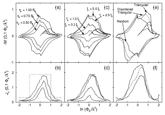
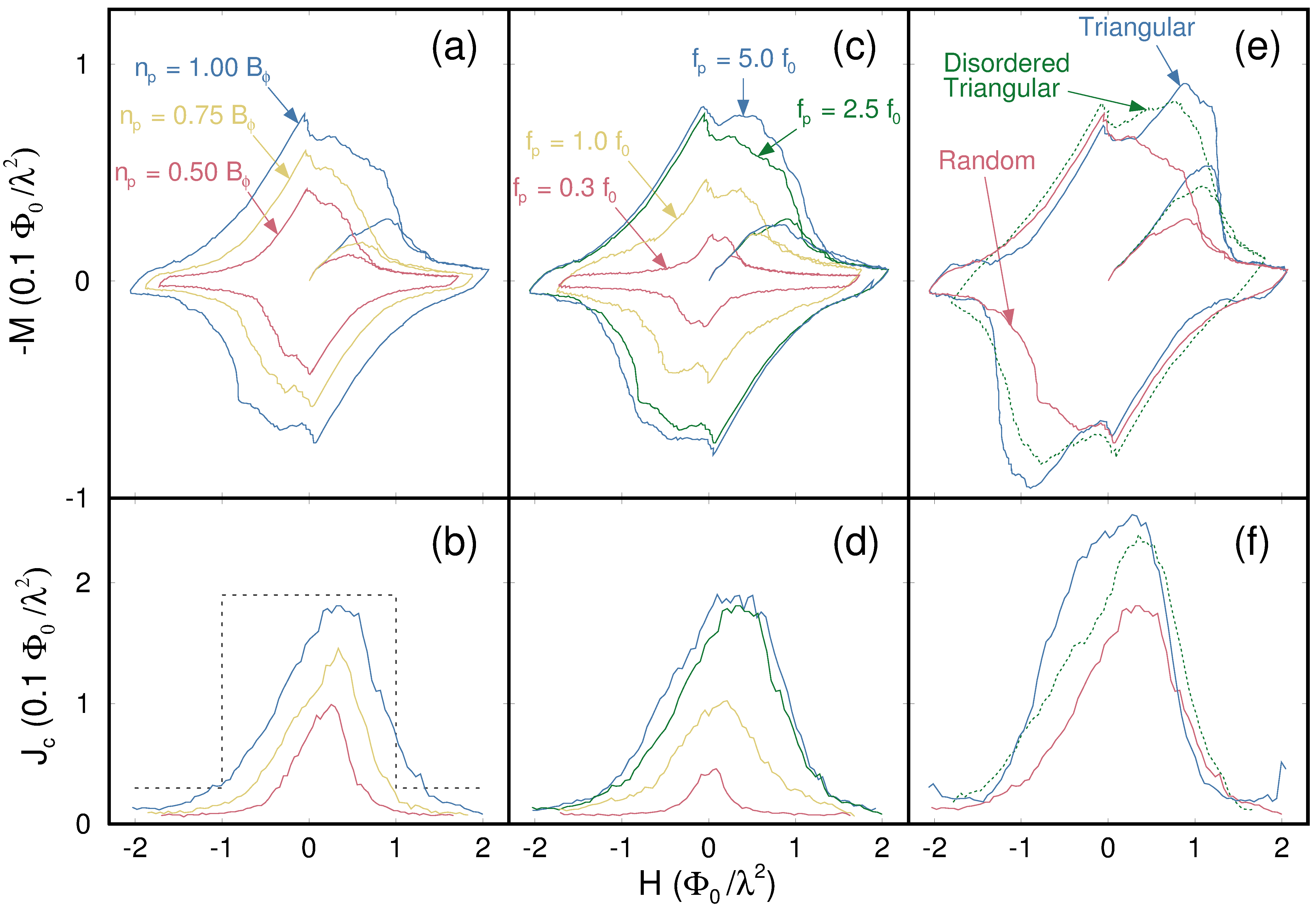
Magnetization loops (top panels) and the corresponding
critical currents (bottom panels) for several samples.
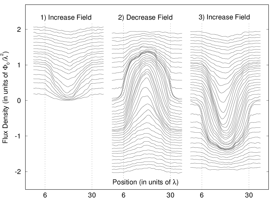
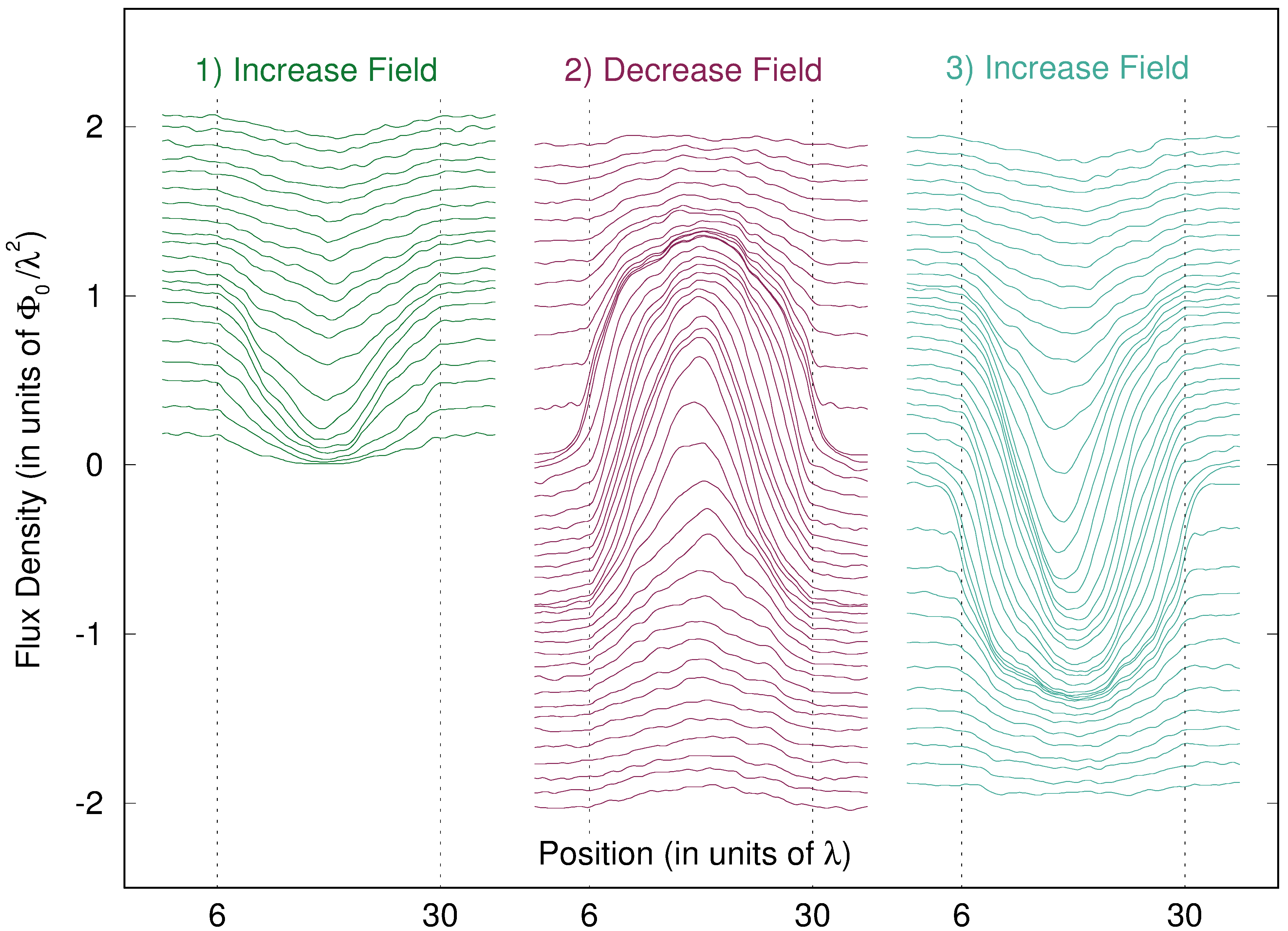
The Jc(B)s are taken directly from the B(x) during "ramp-down"
(e.g., stage (2) in Fig. 1).
In (a,b) fp is held fixed at 2.5f0 and
the density of pinning sites np is varied:
Bϕ/Φ0 = 0.50/λ2, 0.75/λ2, 1.0/λ2.
In (c,d) np remains fixed (Bϕ = 1.0 Φ0 /λ2)
and the pinning strength fp is changed.
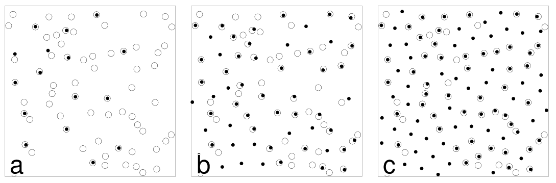
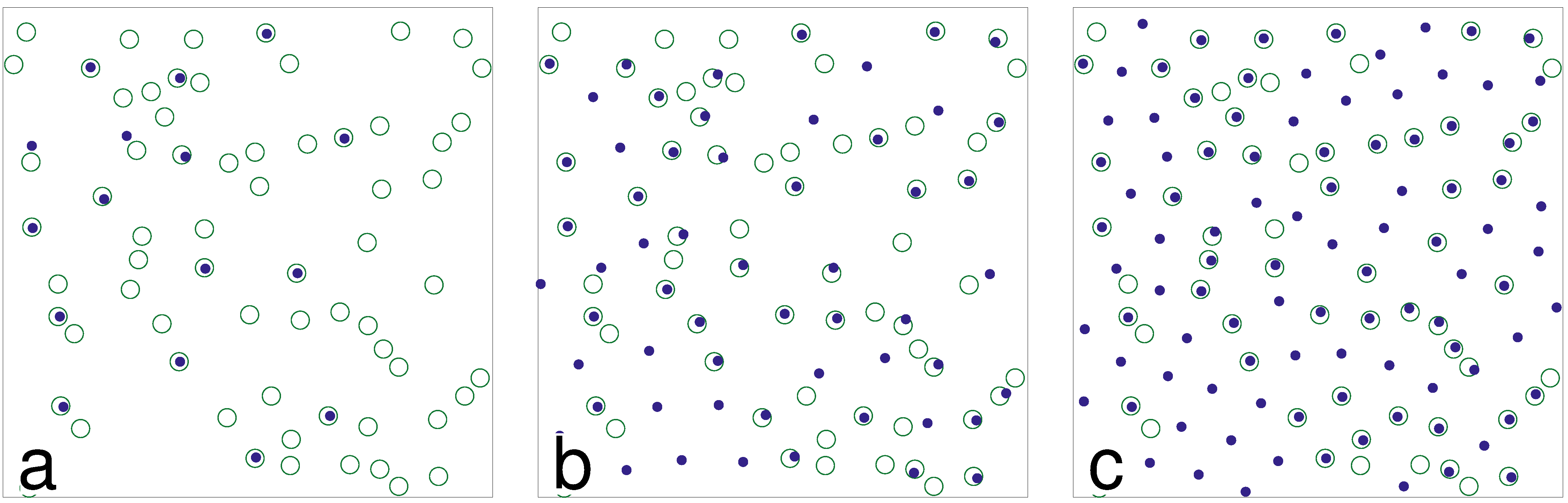
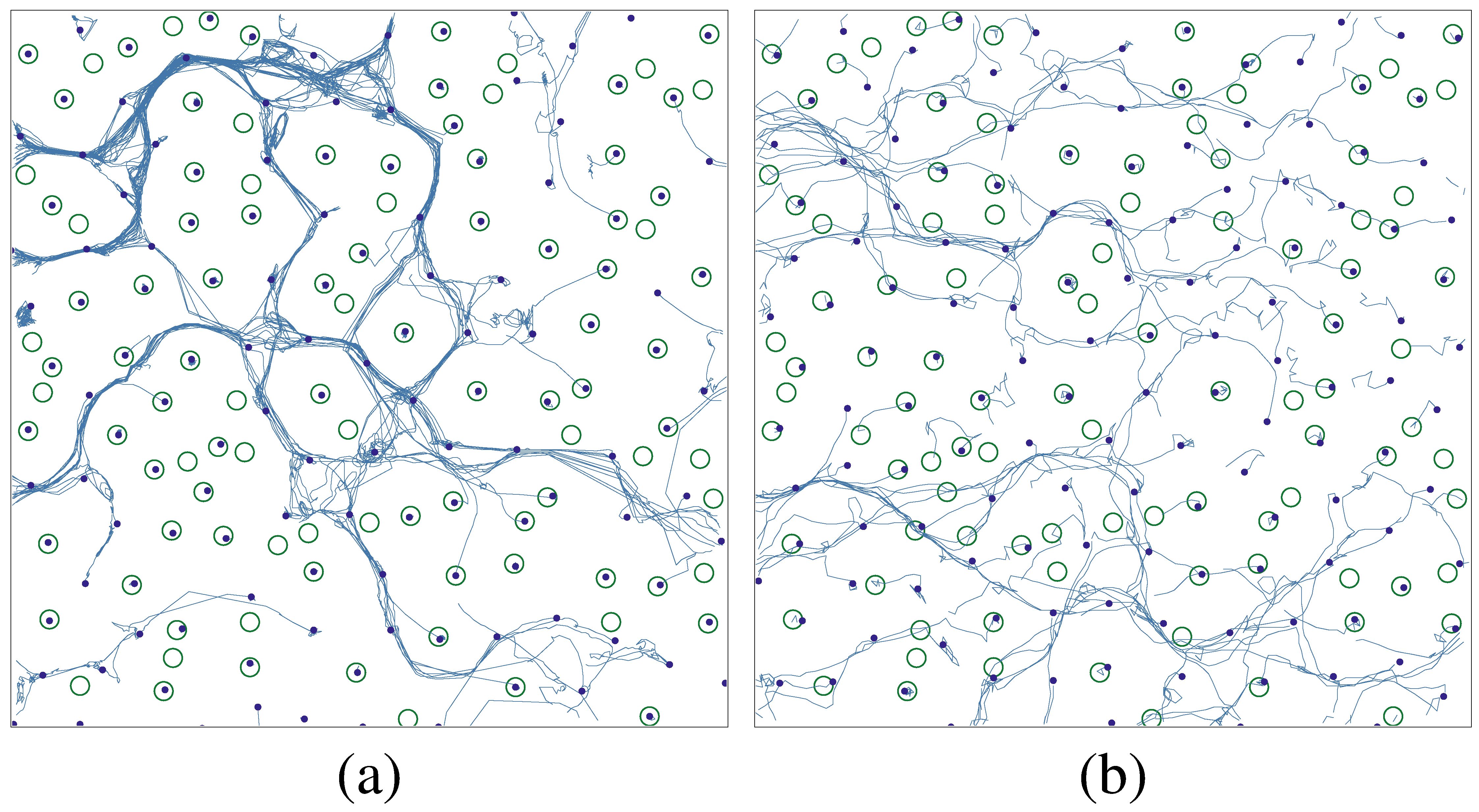
In (e,f) Bϕ = 1.0 Φ0 /λ2, fp = 2.5f0, and the
location of the pinning sites is varied.
(f) shows the significant enhancement of Jc(B) that results
from defects placed in a regular triangular array, as opposed to
random placement.
These results show that even a distorted triangular array of pinning
sites significantly enhances Jc(B) over the case with a random
location of pinning sites.
Color figure
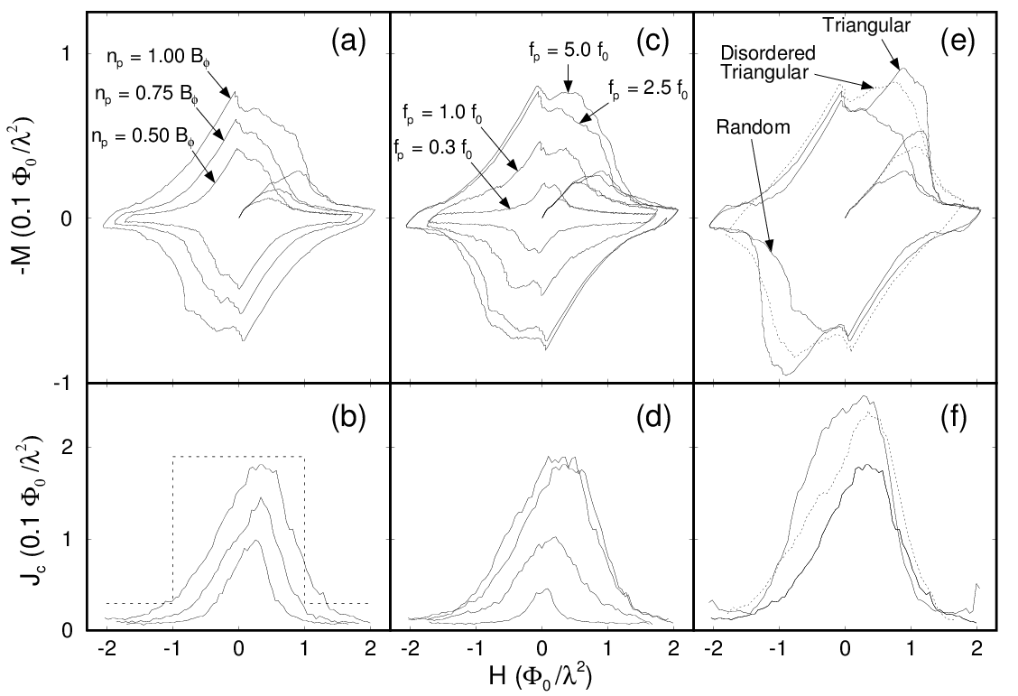
Figure 3:
Magnetization loops (top panels) and the corresponding
critical currents (bottom panels) for several samples.
The Jc(B)s are taken directly from the B(x) during "ramp-down"
(e.g., stage (2) in Fig. 1).
In (a,b) fp is held fixed at 2.5f0 and
the density of pinning sites np is varied:
Bϕ/Φ0 = 0.50/λ2, 0.75/λ2, 1.0/λ2.
In (c,d) np remains fixed (Bϕ = 1.0 Φ0 /λ2)
and the pinning strength fp is changed.
In (e,f) Bϕ = 1.0 Φ0 /λ2, fp = 2.5f0, and the
location of the pinning sites is varied.
(f) shows the significant enhancement of Jc(B) that results
from defects placed in a regular triangular array, as opposed to
random placement.
These results show that even a distorted triangular array of pinning
sites significantly enhances Jc(B) over the case with a random
location of pinning sites.
Color figure
|