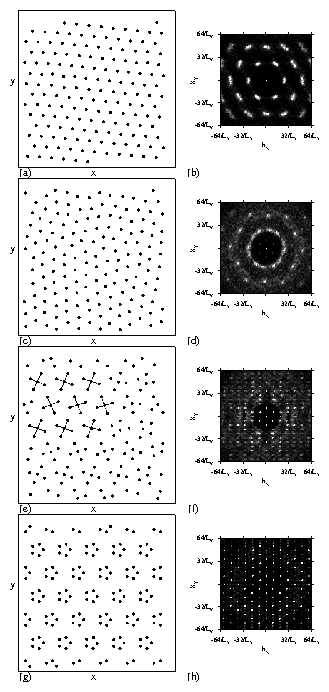
Physical Review E 85, 051401 (2012)

Statics and Dynamics of Yukawa Cluster Crystals on Ordered Substrates

C. Reichhardt and C. J. Olson Reichhardt

Theoretical Division, Los Alamos National Laboratory, Los Alamos, New Mexico 87545, USA

(Received 22 February 2012; published 2 May 2012)

We examine the statics and dynamics of particles with repulsive Yukawa interactions in the presence of a two-dimensional triangular substrate for fillings of up to twelve particles per potential minimum. We term the ordered states Yukawa cluster crystals and show that they are distinct from the colloidal molecular crystal states found at low fillings. As a function of substrate and interaction strength at fixed particle density we find a series of novel crystalline states that we characterize using the structure factor. For fillings greater than four, shell and ring structures form at each potential minimum and can exhibit sample-wide orientational order. A disordered state can appear between ordered states as the substrate strength varies. Under an external drive, the onsets of different orderings produce clear changes in the critical depinning force, including a peak effect phenomenon that has generally only previously been observed in systems with random substrates. We also find a rich variety of dynamic ordering transitions that can be observed via changes in the structure factor and features in the velocity-force curves. The dynamical states encompass a variety of moving structures including one-dimensional stripes, smectic ordering, polycrystalline states, triangular lattices, and symmetry locking states. Despite the complexity of the system, we identify several generic features of the dynamical phase transitions which we map out in a series of phase diagrams. Our results have implications for the structure and depinning of colloids on periodic substrates, vortices in superconductors and Bose-Einstein condensates, Wigner crystals, and dusty plasmas.
I. INTRODUCTION
II. SIMULATION
III. CONFIGURATIONS AND DYNAMICS FOR f = 3, 4, AND 5
IV. CONFIGURATIONS AND DYNAMICS FOR 6 ≤ f ≤ 10
V. HIGHER ORDER FILLINGS AND DISCUSSION
VI. SUMMARY
References


I.  INTRODUCTION

The creation of new types of crystalline or partially ordered states and the dynamics of assemblies of interacting particles have attracted much attention both in terms of the basic science of self-assembly and dynamic pattern formation as well as for applications utilizing self-assembly processes. One of the most extensively studied systems exhibiting this behavior is assemblies of colloidal particles, where the equilibrium structures can be tuned by changing the directionality of the colloid-colloid interactions [1,2]. Since it can be difficult to control and tune the exact form of the interaction, another approach is to use colloids with well defined interactions that are placed on some type of ordered substrate. Optical trapping techniques are one of the most common methods of creating periodic substrates for colloids [3]. Studies of colloidal ordering and melting for one dimensional (1D) periodic substrate arrays have revealed ordered colloidal crystalline structures as well as smectic type structures where the colloids are crystalline in one direction and liquidlike in the other [4,5,6,7,8,9,10,11,12]. These experiments show that the substrate strength strongly influences the type of colloidal structure that forms and that as the substrate strength increases, the resulting enhancement of fluctuations can induce a transition from crystalline to smectic order [4,8,6]. Numerous different colloidal crystalline structures can also appear on 1D substrate arrays of fixed periodicity when the colloid density is varied [7,9].
More recent studies addressed colloidal ordering on two-dimensional (2D) periodic substrates [13,14,15,16,17]. In these systems, the filling factor f is defined as the number of colloids per substrate minimum. For integer fillings f=n, the colloids in each minimum can form an effective rigid n-mer, such as a dimer or trimer [16,17,18,19,20,21,22]. The n-mers have an orientational degree of freedom, and depending on the effective interaction between neighboring n-mers, all the n-mers may align into a ferromagnetically ordered state, sit perpendicularly to their neighbors in an antiferromagnetically ordered state, or form other orientationally ordered states. For square and triangular substrate arrays, n-mer states have been studied up to n = 4 [16,19,20,21]; however, it is not known what structures would form at higher fillings when the simple picture of rigid n-mers no longer applies. Studies of the ordering of bidisperse colloidal assemblies with two different charges on 2D periodic substrates produced novel ordered phases, while a pattern switching could be induced by application of an external field [22]. Similar pattern switching also occurs for colloids with monodisperse charges under external driving [23]. The colloidal n-mer states have been termed "colloidal molecular crystals," and for conditions under which they loose their orientational ordering, they are referred to as "colloidal plastic crystals." Colloidal molecular crystals appear for integer fillings f=n. At fractional fillings such as f=3/2, 5/2, or 7/2, it is possible for ordered composite states to form containing two coexisting species of n-mers; however, for other fractional fillings, the system is frustrated and the n-mer states are disordered [24]. Other studies have shown that novel orderings appear when the 2D substrate array has quasicrystalline order [25].
Once colloidal crystals have formed on a substrate, the driven dynamics can be explored by applying an external driving field to the sample. A variety of dynamical locking phases can occur in which the colloids preferentially flow along symmetry directions of the substrate [26]. As the filling fraction f is varied, a series of peaks in the critical force needed to depin the colloids occurs at integer values of f indicating the existence of commensurability effects [27]. Recent experiments with strongly interacting colloids on two periodic arrays show that kink-type dynamics can occur near f=1 [28]. It would be interesting to explore higher fillings where new types of dynamics could emerge [29].
Many of the same types of phenomena found in colloidal molecular crystals can also be realized for other systems that can be modeled as interacting particles in the presence of a 2D periodic substrate. For example, the antiferromagnetic ordering of dimer colloidal molecular crystals on a square substrate was reproduced using vortices in Bose-Einstein condensates confined by optical traps with two vortices per trap [30] as well as with vortices trapped by large pinning sites in type-II superconductors [31,32,33]. Experimental and numerical studies of molecular ordering on periodic substrates show similar orderings [34]. Other systems where similar states could be realized include classical electrons or dusty plasmas with some form of substrate as well as crystalline cold atoms on optical lattices.
To our knowledge, previous studies of Yukawa interacting colloidal molecular crystals have focused only on systems with up to four colloids per trap. For the case of three colloids per trap, only a limited number of studies have considered the dynamics, and even in this limit there are several new features that we describe for the first time in this work. We show that at high fillings, the rigid n-mer picture breaks down and new cluster and ring states form. Several general features of the statics and dynamics emerge at these larger fillings which are independent of the specific filling.
One of the key findings in our work is the development of orientationally ordered shell structures at higher fillings for the 2D arrays. The development of particle shell structures was studied previously for repulsive particles in isolated individual traps, in systems that include classical charges [35], Wigner islands [36], dusty plasmas [37], colloids [38,39,40,41,42], charged balls in traps [43], and vortices in confined geometries [44,45]. The shell ordering in these systems can be altered by the shape or type of trap as well as by competing attractive and repulsive interactions between the particles [46,47]. In our system, the particles within each shell can exhibit an additional ordering due to interactions with particles in the neighboring traps. We show that as a function of substrate strength, a rich variety of colloidal cluster crystals can be created depending on the filling, and that certain shell structures are more stable than others. The number of particles in the shells and the number of shells depend on the substrate strength, and in certain cases the particles form ring structures instead of shells. We also find reentrant ordered phases as a function of substrate strength. For weak and strong substrates, the system is ordered; however, for substrates of intermediate strength, the system is generally disordered. We find that the depinning threshold can show distinct changes at the boundaries between these different phases as a function of substrate strength, and remarkably, we find that in some cases it is possible for the depinning force to decrease with increasing substrate strength. The velocity-force curves contain clear signatures of the different phases corresponding to different modes of depinning.

II.  SIMULATION

We consider a 2D system with periodic boundary conditions in the x and y directions. The sample contains Nc particles interacting with a triangular sinusoidal substrate containing Ns potential minima. We focus on the case where the number of colloids Nc is an integer multiple of Ns such that f=Nc/Ns = n, where f is the filling factor and n is an integer. A single particle i responds to forces according to the following overdamped equation of motion:
d R

dt
= Fcci + Fsi + Fext + FTi.
(1)
The particle-particle interaction force Fcci = −∑NcjiV(Rij) and the particle interactions are of a Yukawa form, V(Rij) = E0exp(−κRij)/Rij, where E0 = Z2*/4πϵϵ0a0, ϵ is the solvent dielectric constant, Z* is the effective charge, 1/κ is the screening length, a0 is the unit of length which is of order a micron, and Rij = |RiRj|. We model the substrate as a triangular lattice,
Fsi = 3

k=1 
Asin
bk

a0

[cos(θk)
^
x
 
− sin(θk)
^
y
 
]
(2)
where bk = xcos(θk) − ysin(θk) + a0/2, θ1 = π/6, θ2 = π/2, and θ3 = 5π/6. A is the amplitude of the substrate potential and we consider systems with Ns=120 minima. The initial colloid positions are obtained by simulated annealing, where the colloids start in a high temperature molten state and are gradually cooled to a finite temperature or to T = 0. We have also considered other initialization procedures, including placing a commensurate number of colloids in each substrate minima and letting the system relax. This procedure gives very similar initial states as the simulated annealing, especially for strong substrates; however, for weaker substrates the configuration obtained through simulated annealing is generally more disordered, as we discuss in more detail later. After annealing, we investigate the transport properties by applying an external drive Fext = FDx. We increment FD from FD=0 to some final value in steps of δFD, and we wait 106 simulation time steps between increments to avoid transient effects. The depinning threshold is obtained by measuring the average colloid velocity V = N−1cNci (d Ri/dt) ·x. The value of δFD is modified according to the strength of the substrate. For weaker substrates we use smaller values of δFD in order to obtain an accurate depinning threshold.

III.  CONFIGURATIONS AND DYNAMICS FOR f = 3, 4, AND 5

We first consider the cases f = 3, 4, and 5. Earlier numerical studies addressed the statics and dynamics for f = 2 and 3 and showed that for strong triangular substrates, f = 2 produced a herringbone state that transitioned under an applied drive into an aligned ferromagnetic state where the particles move in 1D channels [27]. For weaker substrates a triangular lattice formed and the depinning was elastic, while for intermediate substrate strengths the depinning was plastic and the herringbone state depinned into a fluctuating state that reordered at higher drives. There was a strong increase in the critical depinning force between the elastic and plastic depinning regimes similar to the peak effect phenomenon found at the transition between elastic and plastic depinning for vortices in type-II superconductors. For f = 3 the pinned state was always triangular and for weak substrates the particles depinned into either a moving crystal or a moving smectic state. At these low fillings it was also shown that for weak substrates the critical depinning force FcA2, as expected for elastic depinning, while for strong substrates, FcA, as expected for single particle depinning.
Fig1.png
Figure 1: (a, b) The particle locations (black dots) for a triangular substrate at a filling of f = 3 for different substrate strengths of (a) A = 1.0 and (b) A=3.0. In (b) the trimer states that form at each trap are aligned. (c) The structure factor S(k) corresponding to panel (a) at A=1.0. (d) S(k) corresponding to panel (b) at A=3.0 shows long range order and some features at larger k values corresponding to the smaller real space length scale of the trimers.
We now consider several features at f = 3 that were not reported in the earlier studies, including the velocity-force curves and an additional dynamical phase. Figures 1(a) and 1(b) show the particle configurations at f = 3 for A = 1.0 and A=3.0, respectively, while Figs. 1(c) and 1(d) show the corresponding structure factor S(k). For A = 1.0 in Fig. 1(a,c), a triangular lattice forms with one dominant length scale that is the distance between the particles. For A = 3.0 in Fig. 1(b,d), each substrate minimum clearly captures three particles and the structure factor has the signature of two length scales. There is a well defined hexagonal pattern of maxima in S(k) surrounding the origin in Fig. 1(d) that was not present in Fig. 1(c) which is associated with the longer length scale of the substrate minima locations. The hexagonal void arrangement at larger k values in Fig. 1(d) is associated with the smaller length scale of the trimer colloid arrangement within each substrate minimum. In general, as A increases further, the structure of the lattice remains the same as shown in Fig. 1(c,d) except that the trimers gradually reduce in size.
Fig2.png
Figure 2: The average velocity V vs external drive FD for the f = 3 system in Fig. 1 for A = 1, 2, 3, 4, 5, and 6, from left to right. For A = 4.0 the three different phases are labeled for the pinned (P), random flow (R), and moving smectic (MS) phases. For the A = 2.0 curve there is no random phase but two different elastic flow phases EF1 and EF2 occur which are labeled with lines.
Fig3.png
Figure 3: (a) Particle positions (dots) and trajectories (lines) over a fixed time interval for the random phase at FD=0.9 and A = 4.0 for the f=3 sample from Fig. 2. The trajectories are rapidly changing with time and mixing of the particles occurs. (c) The corresponding S(k) shows sixfold peaks at small k due to the overall triangular ordering of the particles on the substrate as well as a ring structure at larger k due to the liquidlike nature of the particle positions. (b) Particle positions (dots) and trajectories (lines) over a fixed time interval in the moving smectic phase at FD=1.5 for the same sample, where the particles follow well-defined winding quasi-1D paths. (d) The corresponding S(k) shows more ordering, including more pronounced peaks along ky that are consistent with a smectic phase.
In Fig. 2 we plot the average particle velocity V versus the external drive FD for A = 1, 2, 3, 4, 5, and 6. For the A = 4.0 curve we have labeled the different dynamical phases. The pinned phase (P) transitions into a rapidly fluctuating phase we term the random phase (R). The random phase is characterized by rapid mixing of the particles, as illustrated in Fig. 3(a) for A = 4.0 at FD=0.9, where the particle trajectories show significant excursions in the direction transverse to the drive and are continuously changing with time. In Fig. 3(b), the corresponding S(k) taken from a snapshot of the particle positions in the random phase shows features of an anisotropic liquid. There is triangular ordering in S(k) at smaller k values due to the underlying triangular substrate; however, the higher order peaks of Fig. 1(d) that indicated long range order in the pinned state are replaced in Fig. 3(b) by a ring structure characteristic of a liquid. We also find a larger number of peaks along ky compared to kx due to the anisotropy induced by the x-direction drive. For higher drives the system transitions into a state with no transverse diffusion, as illustrated in Fig. 3(b,d) for a sample with A=4.0 at FD = 1.5. In this state, which we term the moving smectic (MS) phase, the motion is confined to winding quasi-1D flows as shown in Fig. 3(b). The plot of S(k) in Fig. 3(d) indicates that the MS state has stronger partial ordering than the random phase but that there is still a tendency for the system to be more ordered along the ky direction.
The R to MS transition is correlated with a decrease in V with increasing FD, producing a negative dV/dFD signature known as negative differential conductivity (NDC). Simulations and experiments on superconducting vortices moving over periodic pinning sites have revealed NDC at transitions from random or turbulent flows to ordered 1D flows [48]. The NDC in the vortex system is much more pronounced than the NDC we observe in Fig. 2, and this is likely due to the difference in the type of substrate used in the two systems. For the vortex system, artificially fabricated pinning sites produce a short range muffin-tin potential that permits some vortices to sit completely outside of the pinning sites in the flat interstitial regions. In the random phase, a large number of vortices move through the interstitial areas and do not interact directly with the pins, but at the transition to 1D flow, these vortices suddenly fall into flowing channels that pass through the pinning sites, abruptly increasing the effective amount of drag exerted by the pinning sites on the vortices. In the sinusoidal triangular substrate we consider here, there are no interstitial regions and the moving particles are always experiencing some drag from the pinning. Additionally, in the vortex system NDC was only associated with fillings just above f=1, the first matching field [48], while in Fig. 2 we find no NDC until f ≥ 3. We note that the NDC for the triangular substrate is much more robust than NDC in the vortex system since it appears for a much wider range of fillings, including incommensurate fillings. In a recent vortex experiment [49] NDC did not occur until f > 2.5; however, this effect could not be reproduced in vortex simulations using only muffin-tin type pinning potentials. This could mean that for the particular system considered in Ref. [49], despite the fact that the pinning sites are localized, longer range interactions between the pins or distortions of the substrate may have caused the substrate to behave more like the sinusoidal type of substrate we consider here rather than like a muffin-tin potential.
Fig4.png
Figure 4: Particle positions (dots) and trajectories (lines) over a fixed time interval in the elastic flow phases from the f=3 sample in Fig. 2 at A = 2.0. (a) In phase EF1 at FD=0.25, the particles form a triangular lattice and flow through winding channels but there is no particle mixing. (b) In phase EF2 at FD=0.5, the trajectories become straight. The transition between these two phases appears as a kink in V near FD=0.32 in Fig. 2.
For A > 4.0 we find the same three phases described for A=4.0, with the transitions between phases shifting to higher FD with increasing A. In Fig. 2 we identify two distinct phases observed for a weaker substrate with A = 2.0. Here the random phase is absent and the system depins elastically, with no sharp jump in V at depinning as found for A > 2.0 when the flow above depinning is plastic. Even though the depinning transition for A=2.0 is elastic, we still find transitions between distinct dynamical phases that can be identified through signatures in the velocity-force curve. In Fig. 2 we mark the two elastic flow phases EF1 and EF2 that appear on either side of a discontinuity in dV/dFD centered at FD=0.32. In both phases the particle lattice is triangular and has an S(k) similar to that shown in Fig. 1(b). The EF1 and EF2 phases also appear for A=3.0 with the kink in V shifted up to higher FD. In Fig. 4(a) we plot the particle trajectories in phase EF1 for the A=2.0 system. The triangular particle lattice moves in a zig-zag pattern in order to avoid passing over the potential maxima of the triangular substrate. At higher drives the particles no longer avoid the potential maxima and enter phase EF2 where they move in the direction of drive, as illustrated in Fig. 4(b).
Fig5.png
Figure 5: (a,c,e) The particle configurations and (b,d,f) corresponding S(k) for samples with f = 4. (a,b) At A = 1.0 the particles form a triangular lattice. (c,d) At A = 8.0 a quadrimer state forms. The quadrimers have a ferromagnetic alignment. (e,f) At A = 11.0 the quadrimer state has no orientational ordering, producing ring structures in S(k).
For f = 4, when the substrate is weak a triangular lattice of particles forms, as illustrated in Fig. 5(a,b) for a sample with A=1.0. Weak substrates still affect the lattice by breaking rotational symmetry and causing the particle lattice to preferentially orient in a direction determined by the filling factor. At f=4, one of the symmetry axes of the particle lattice is aligned with the x axis as in Fig. 5(a), while in Fig. 1(a) at f=3 it was aligned with the y axis. As the substrate strength increases for f=4, quadrimer arrangements of the particles form in each substrate minimum, and the orientation of neighboring quadrimers varies with A. For A = 8.0, Fig. 5(c) shows that all the quadrimers are aligned in the same direction. The corresponding S(k) in Fig. 5(d) shows sixfold peaks at small k from the triangular substrate, while at larger k a fourfold void structure appears due to the square ordering of each quadrimer. At A = 11 in Fig. 5(e), the individual quadrimers remain intact but their long range ferromagnetic orientational ordering is lost, producing a ring structure in S(k) as shown in Fig. 5(f). We have tried several different methods of preparing the initial configuration for f=4 and A=11.0 but have not found a ferromagnetically ordered state.
The orientational ordering of dimer and trimer states was previously shown to arise due to quadrupole or higher pole moment interactions between neighboring n-mers. For quadrimers, it is likely that the higher pole moments play a more important role. If the pole moment favors ferromagnetic alignment, than as A increases the size of the quadrimer decreases, reducing the pole moment responsible for the orientational ordering. Previous studies found that as the substrate strength increases, the temperature at which dimers and trimers lose their orientational ordering drops due to the decreasing effective pole moment. We note that the configurations in Fig. 5 are all obtained at T = 0.0. When we anneal the system from a high temperature and slowly decrease the temperature to zero, we still obtain the same states illustrated in Fig. 5, suggesting that the energy of the ferromagnetic state must be only slightly smaller than that of the rotationally disordered state. As A increases, the picture of rigid quadrimers begins to break down, as shown in Fig. 5(e) where the quadrimers become slightly distorted. This could further decrease the contributions of different pole moments to the orientational ordering or may even lead to competing interactions between neighboring quadrimers, resulting in a ground state with ordering produced by very long range interactions, as found in certain spin ice systems. For A > 11.0 we find states similar to those shown in Fig. 5(e,f) with increasing distortion in the square ordering, until for high enough A the distortion becomes strong enough to permit some particles to sit at the center of a substrate minimum. The dynamic phases for f=4 are similar to those illustrated in Fig. 2 for the f=3 system, with elastic depinning for low A crossing over to plastic depinning at higher A, followed by a dynamical reordering transition at higher FD.
Fig6.png
Figure 6: 
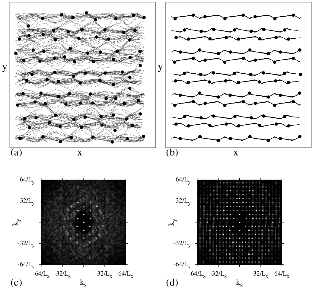
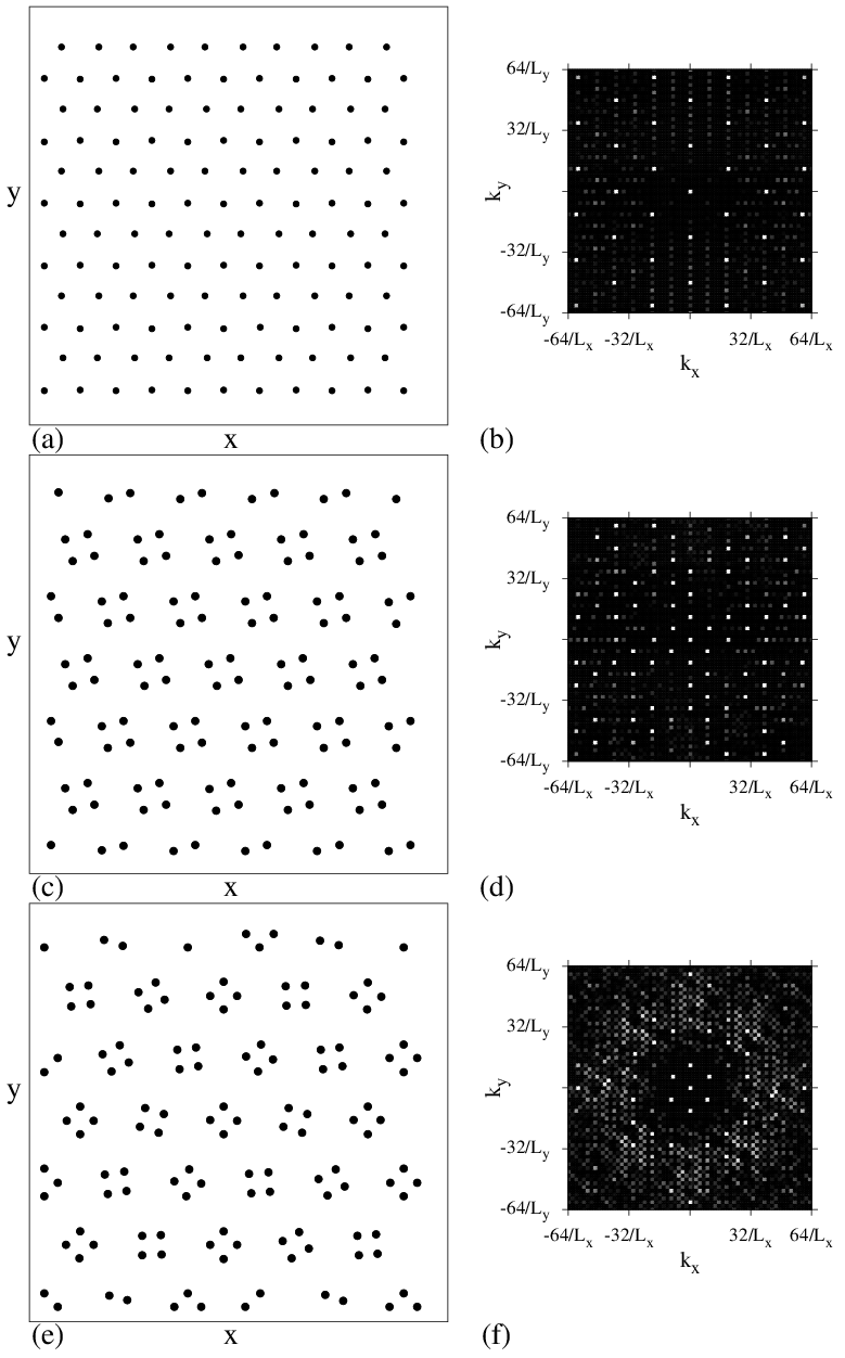
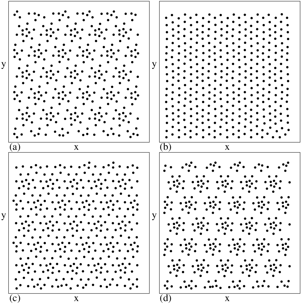
(a,c,e,g) The particle configurations and (b,d,f,h) corresponding S(k) for samples with f = 5. (a,b) At A = 0.5 the particles have triangular ordering that is not commensurate with the substrate, as indicated by the smearing of the peaks in S(k). (c,d) At A = 1.75 the system is disordered. 
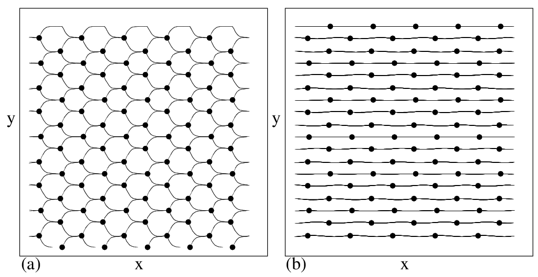
(e,f) At A = 4.1 the system forms what we term a jack state with one particle located at the center of each potential minimum surrounded by four outer particles in a square configuration. In large regions the squares form a herringbone structure, as indicated by the dashed lines; however, some localized disorder is present in the sample. (g,h) At A=11.0, an aligned pentagon state with long range orientational order forms. For A > 11.0 the same structure persists but the pentagons shrink in size.
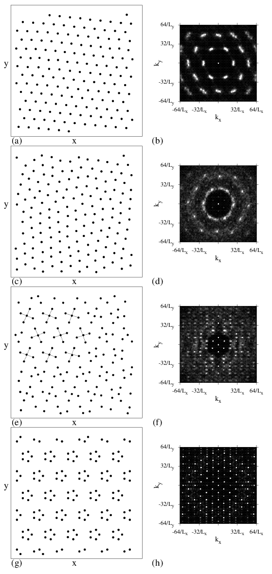
For f = 5 at FD=0, as a function of A we find disordered phases interspersed among ordered phases. This is also the first filling at which the n-mer assumption breaks down and a shell structure of the particles in each substrate minimum begins to form, in contrast to the case of isolated trapped clusters of repulsively interacting particles, which first develop equilibrium shell structure at f=6 [35,37,43,50,51,52,53] but have a metastable state with one particle in the center for f=5 [54]. In Fig. 6(a) for A=0.5 at f=5, a triangular lattice containing a small tilt distortion forms. The smearing of the corresponding S(k) in Fig. 6(b) indicates that for weak substrates at this filling, the particle lattice is not commensurate with the substrate. At A = 1.75, shown in Fig. 1(c,d), the lattice is disordered as indicated by the ring pattern in S(k). When we vary the initialization protocol, we always observe a disordered lattice for 0.9 ≤ A ≤ 2.0. For 2.0 < A < 7.0 the system orders again as shown in Fig. 6(e,f) for A = 5.0. Each substrate minimum contains what we term a jack pattern consisting of one particle located at the center of the minimum surrounded by four particles in a square arrangement. As indicated by the dashed lines in Fig. 6(e), the jacks are tilted at +20° or −20° to the x axis in every other row, producing a herringbone structure. The ordering is not complete as there are local regions where the jack structure breaks down, producing some smearing in S(k) as plotted in Fig. 6(f). The structure can be viewed as the beginning of a shell ordering where, in each substrate minimum, the first shell contains a single particle and the next shell contains four particles. For A > 7.0 the interactions between particles in neighboring substrate minima are reduced and the pentagon ground state structure expected for particles in an isolated trap emerges. The pentagons exhibit ferromagnetic order and are all aligned in the same direction, as illustrated in Fig. 6(g,h) for A=11.0. For increasing A the pentagons become smaller; however, we observe no further change in the structure.
Fig7.png
Figure 7: The velocity V vs force FD curves for samples with f = 5. (a) At A = 2.15 we observe a pinned phase (P), a random phase (R), and a moving crystal phase (MC). (b) At A = 4.1 the system depins into a moving channel phase (C) illustrated in Fig. 8(a). This is followed by the R phase and the moving smectic phase (MS). (c) At A = 7.2 the C phase is absent and the system transitions directly from the R phase to the MS phase.
Fig8.png
Figure 8: Particle positions (dots) and trajectories (lines) over a fixed time interval for the f=5 sample. (a) The moving channel (C) phase at A = 4.1 and FD=0.05. (b) The moving smectic (MS) phase at A = 7.2 and FD=1.1.
We can relate the different pinned structures at f=5 to features in the velocity force curves and to dynamic phases. For A < 1.5 there is an elastic depinning into a moving triangular lattice. For 1.5 ≤ A < 2.4 the disordered phase depins into a fluctuating random phase similar to that observed for f = 3, and at higher drives the system can reorder into a moving crystal (MC) phase. In Fig. 7(a) we plot V versus FD for a sample with A = 2.15. The random flow phase is characterized by large fluctuations, and is followed by a sharp transition near FD = 0.034 into a MC phase with small fluctuations. The transition between these two phases can also be detected by analyzing the noise fluctuations of the velocity response. In the random phase the fluctuations are characterized by a broad band noise signal with 1/fα characteristics where α = 1.5 to 2.0, while in the MC phase there is a narrow band signal with a characteristic frequency that increases with increasing FD, similar to what has been observed for dynamically reordered phases of superconducting vortices moving over periodic substrates [48]. For 2.5 < A < 3.3 we find no dynamical reordering and the particle arrangement remains disordered up to the highest drives we considered; however, it is possible that a transition into a moving ordered state could occur at very high drives. For 3.1 < A < 6.1, where the pinned system is in the ordered jack state, the depinning is elastic and the particles depin into the ordered winding channel flow phase (C) illustrated in Fig. 8(a). As FD increases, there is a crossover to a random phase followed by another transition at high drives into a moving smectic phase (MS) of the type shown in Fig. 8(b). The velocity signatures associated with these transitions appear in Fig. 7(b) for a sample with A=4.1. The C phase is associated with small velocity fluctuations and is followed first by the strongly fluctuating R phase and then by the MS phase at higher FD. For A ≥ 6.0 the C phase is lost and the sample depins from the ordered pentagon state into a random flow state, as illustrated in Fig. 7(c) for a sample with A=7.2. This is followed by the formation of a moving smectic state at higher FD. As A increases, the extent of both the pinned region and the random fluctuating state increases.
Fig9.png
Figure 9: (a) The dynamical phase diagram FD vs A for a sample with f = 5. Regions where the P, C, MC, R, and MS phases occur are marked. (b) The depinning curve Fc from panel (a) plotted on a log-log scale. Dashed lines mark the transitions between the pinned triangular crystal (PC), pinned disordered or pinned glass (PG), pinned jack (PJ), and pinned pentagon (PP) states. (c) The critical depinning force Fc vs A for f = 1, 3, 4, and 5, from top to bottom. Upper dashed line: a linear fit FcA. Lower dashed line: a fit to FcA2. These curves indicate that, in general, the system exhibits collective depinning behavior.
By conducting a series of simulations, we map the dynamic phase diagram shown in Fig. 9(a). The disordered R phase separates the moving crystal and moving smectic phases. There is also a domelike region where the winding channel C phase occurs. In Fig. 9(b) we plot the depinning line on a log-log scale with dashed lines marking the regions where the pinned phases illustrated in Fig. 6 occur. For A < 0.9, the depinning force Fc monotonically increases with increasing A. There is a small decrease in Fc at the onset of the pinned disordered or pinned glass (PG) phase, followed by a plateau in Fc. Near A = 3.0, Fc begins to increase rapidly with increasing A in the pinned jack state, while in the pinned pentagon state Fc still increases with increasing A but with a reduced slope. The behavior of Fc near the onset of the pinned disordered phase is somewhat unusual since it indicates that even though the substrate strength is increasing, the depinning force does not increase. When the system is disordered, there are numerous dislocations present in the particle structure that produce weak spots which flow first at the depinning transition. In contrast, in the depinning of a crystalline state, there are no weak spots since the lattice structure is the same everywhere. This behavior is the opposite of the so-called peak effect phenomenon found for vortices in type-II superconductors, where a sudden increase in Fc occurs when the vortex lattice becomes disordered. The peak effect is generally believed to arise due to the softening of the vortex lattice when dislocations are present. In the softer lattice, the vortices can more freely move to adjust to a random pinning potential and maximize the pinning force. In our system, the pinning potential is not random, so the crystalline states are more strongly pinned than the disordered states. This has been demonstrated clearly in studies of commensurate-incommensurate transitions for both vortices and colloids in periodic substrates, where crystalline states form at integer values of f. Near but not at commensuration, numerous defects appear in the commensurate lattice, and these defects cause a reduction in Fc. As a result, Fc passes through a series of peaks at integer values of f as the filling fraction is varied. In the system we are considering here, the f = 5 state is unusual since even through the system is at an integer filling, we find a regime where the pinned state is noncrystalline. This is in contrast to the lower integer fillings f=1, 2, 3, and 4, where all the pinned states are ordered. This disordering effect and the plateau or drop in Fc at intermediate substrate strengths in the disordered pinned regions is a general feature of f ≥ 5 systems at integer fillings, and both features becomes more prominent for higher fillings. It may appear from Fig. 9(b) that the plateau in Fc occurs in the disordered region and not in the pinned jack state; however, the plateau persists into a window of the pinned jack state since the PJ state contains some defects.
In Fig. 9(c) we plot Fc vs A for samples with f = 1, 3, 4, and 5. The dynamics and configurations of the f = 2 system were described in detail in previous work [27]. For f = 1 we find that FcA, as indicated by the upper dashed line. This is expected in the limit of single particle depinning and indicates that particle-particle interactions are unimportant at depinning for this filling. For the higher fillings f > 1, we instead find FcA2 as indicated by the lower dashed line. This is characteristic of collective depinning transitions, where the interactions among the particles within each minimum play an important role in the depinning process. In the limit of very strong substrates, the depinning generally occurs when one particle is pushed near the saddle point of the substrate by the other particles in the potential minimum. This single particle suddenly escapes and triggers a cascade of escape events in the rest of the system. At intermediate substrate strengths, the higher order fillings all generally show a change in the slope of Fc versus A associated with a change in the n-mer structure.

IV.  CONFIGURATIONS AND DYNAMICS FOR 6 ≤ f ≤ 10

Fig10.png
Figure 10: Fc versus A. (a) At f = 6, a sharp increase in Fc occurs at the transition from a pinned triangular lattice to a disordered state. Dashed lines indicate regions where different pinned phases appear. Triangular: triangular lattice; Disordered: disordered state; Pentagon/Triangular: a monomer at the center of each well surrounded by five particles arranged in a pentagon; Hexagon: a hexagonal ring in each substrate minimum. (b) At f = 7, the triangular to disordered transition is associated with a small dip and a plateau in Fc with increasing A. Dashed lines indicate the regions where different pinned states appear. Triangular: triangular lattice; Disordered: disordered state; Pentagon/Dimer: a composite pentagon-dimer arrangement in each minimum; Hexagon/Monomer: a composite hexagon-monomer arrangement in each minimum; Ring: a single ring of particles in each minimum found at large A.
Fig11.png
Figure 11: The particle positions after annealing for a sample with f = 6. In panels (c,d,e), dashed lines indicate the orientation of the pentagons in selected traps. (a) At A = 1.0 and FD=0 a triangular state forms. (b) At A = 2.75 and FD=0 a disordered state occurs. (c) At A = 6.0 and FD=0 there is a pentagon/monomer state with no orientational order. (d) At A = 12.0 and FD=0 we find an aligned pentagon/monomer state. (e) At A = 12.0 and FD=0.45, just below the depinning transition, the pentagon/monomer state is polarized by the applied drive. (f) At A=17.0 and FD=0, a hexagonal ring state with orientational order forms. Dashed lines indicate the two hexagon alignments in representative traps. (g) S(k) for the disordered phase in panel (b). (h) S(k) for the hexagonal ring state in panel (f).
In Fig. 10(a) we plot Fc versus A for a sample with f = 6. A large jump in Fc occurs at A=2.5 at the transition from a pinned triangular lattice, illustrated in Fig. 11(a), to a disordered pinned state, illustrated in Fig. 11(b). For 2.5 < 5.5, the system becomes disordered, as shown in Fig. 11(b) for A = 2.75, and has a ringlike S(k) signature, shown in Fig. 11(g). In the disordered region the system depins into a plastic random flow state, while for A < 2.5 the system depins elastically into a MC state. At this filling, Fc is depressed in the triangular state since it is not possible for all the particles to simultaneously be in a triangular lattice and sit at substrate minima locations, so that some particles are instead located on substrate maxima. When the substrate strength increases enough, the particles are forced off of the substrate maxima and the system disorders, allowing more particles to be located closer to substrate minima. For 5.5 < A < 15, a shell structure emerges. The system forms a pentagonal/triangular lattice composite in which one particle sits at each substrate minimum and is surrounded by five particles in a pentagon arrangement, as illustrated in Fig. 11(c) for A = 6.0. In this case the ordering is not ferromagnetic and the tilt of the pentagons varies from site to site; however, for A > 8.0 the pentagon-monomer states become aligned, as shown in Fig. 11(d) for A = 10. An applied drive can induce a polarization of the pentagons in the driving direction, as illustrated in Fig. 11(e) for A = 12.0 under an x direction drive just before depinning. For A > 15 a ring state forms in which the center of the substrate minimum is empty and the particles form a hexagon. The rings are not all aligned; instead, two orientations coexist in the sample as shown in Fig. 11(f). This produces twelve-fold modulations in the structure factor as illustrated in Fig. 11(h). As A increases further, the ring structure persists but decreases in diameter. In general we find ring structures rather than shell structures for f ≥ 6 at large A. The different phases are highlighted in Fig. 10(a).
Fig12.png
Figure 12: The particle positions after annealing for a sample with f = 7. (a) The disordered state at A = 4.0. (b)At A = 12.0 a pentagon/dimer composite appears in which the dimers are partially aligned. Dashed lines indicate two different pentagon/dimer orientations. (c) At A = 20.0 a hexagon/monomer composite forms. Dashed lines indicate two different hexagon orientations. (d) At A=25.0 a ring structure appears with seven particles per ring.
Figure 10(b) shows that a similar set of pinned phases forms in a sample with f = 7. There is still a triangular lattice for small A; however, at A=3.75 when the system enters the disordered phase, Fc shows a small decrease followed by a plateau up to the end of the disordered phase at A=7.0. For f=7 the triangular lattice is more commensurate with the substrate and thus better pinned than the triangular lattice at low A in the f=6 system. In the disordered phase, illustrated in Fig. 12(a) for A=4.0, S(k) contains a ringlike structure similar to that in Fig. 11(g). For 7.0 < A < 16 the system forms a shell structure with an outer pentagon and two dimerized inner particles, as shown in Fig. 12(b) for A = 12.0. The pentagon/dimer structures are only locally aligned, leading to smearing in the corresponding S(k). Figure 12(c) illustrates the configuration at A = 20.0 where an array of hexagons appears with a monomer at the center of each hexagon. The hexagons have one of two possible orientations, similar to the f=6 hexagon state shown in Fig. 11(f). For A = 25 shown in Fig. 12(d), the shell ordering is replaced by a ring structure where each ring has seven particles and the ring radius decreases with increasing A. As also found for the f = 6 case, it is possible for an external drive to orient the structures close to depinning.
The dynamical phases for f = 6 and f=7 are very similar to those observed at f = 5. The system depins elastically at small A in the triangular ordering regime and depins plastically in the disordered pinned regime. A disordered flow regime extends to divergingly large drives for regions of A where a disordered pinned phase is present. For values of A above the disordered pinned phase, the strongly driven system dynamically orders into a moving smectic phase, and the driving force at which this transition occurs increases with increasing A. For the higher fillings of f=6 and f=7, there are some additional features in the VFD curves at high A that did not appear at f=5. For example, in the fluctuating phase, the system shows a coexistence regime with some particles that remain pinned while other particles move along 1D channels or troughs without rearranging the pinned particles. This feature becomes more noticeable at higher f.
Fig13.png
Figure 13: The particle positions after annealing for a sample with f = 8. In (a,b), dashed circles indicate the centers of the substrate minima. (a) At A = 2.0 a triangular lattice forms that is rotated by 19.1° with respect to the underlying substrate. The dashed line indicates the direction along which 8 particles fit between consecutive substrate minima. (b) At A = 5.0, dimerization of a subset of the particles occurs and the dimers are aligned approximately −41° from the x axis. The dashed line indicates the lattice alignment direction, and a representative hexagon surrounding one dimer is shown. (c) At A = 20.0, seven particles surround a single monomer in each minimum. (d) At A = 26.0 a ring state appears with eight particles per ring.
For f = 8 there are several new features in the dynamic phases due to the fact that there is no intermediate disordered pinned phase. This results from a matching of the registry of the f=8 lattice with the underlying substrate. At A=2.0 in Fig. 13(a), the particles form a triangular lattice that is slightly anisotropic and rotated by 19.1° with respect to the underlying substrate. This orientation permits as many particles as possible to sit close to substrate minima, and as indicated by the dashed line in Fig. 13(a), along one particle lattice symmetry direction, there are eight particles filling the space between consecutive substrate minima. This arrangement differs from the disordered lattice found at the eighth matching field in a sample with a muffin-tin potential [55]. As A increases, each substrate minimum traps two particles that dimerize and are surrounded by six other particles, as illustrated in Fig. 13(b). The dimers are rotationally ordered, and the overall particle lattice is rotated by 40.89° with respect to the substrate, as indicated by the dashed line in Fig. 13(b). Orientationally ordered dimers did not form for f=5, 6, or 7. For A > 17.0 the dimer state is lost and replaced by a monomer at each substrate minimum surrounded by an outer shell of seven particles, as shown in Fig. 13(c) for A=20.0, and for A > 25.0 a ring state with eight particles per ring occurs, as illustrated in Fig. 13(d) for A=26.0.
Fig14.png
Figure 14: The dynamical phase diagram FD vs A for a sample with f=8. The pinned (P) phases include: a triangular lattice (Triangular), a triangular lattice containing dimers (Triangular/Dimer), heptagons surrounding monomers (Heptagon/Monomer), and a ring state (Ring). There is a large increase in Fc at the onset of the dimerized state. The transition flow region is labeled Tr. The MC, MS, and R flow phases are also marked.
Fig15.png
Figure 15: Main panel: Vx (upper curve) and Vy (lower curve) vs FD for a sample with f = 8 at A = 5.0. P: pinned phase; Tr: transverse flow phase; R: random flow phase with motion oriented along the x direction only. There is a sharp transition between the Tr and R flow phases. Inset: Particle positions (dots) and trajectories (lines) over a fixed time interval for the same sample in the transverse flow phase just above depinning at FD=0.0125. Dashed circles indicate the centers of the substrate minima. The particles do not flow with the applied drive along the x-direction but instead travel at −40.89° to the x axis along one of the principal axes of the particle lattice.
The lack of disorder for f=8 is clearly shown in the dynamical phase diagram in Fig. 14. There are no disordered pinned phases, and the random flow phase (R) does not extend out to large FD but is instead bounded on the high FD side by the MS flow state. For A ≤ 2.0, the triangular lattice depins elastically in the direction of drive into an MC state. There is a sharp increase in Fc at the onset of the dimerized state, and the MC flow is replaced by MS flow at higher drives. For 4 ≤ A < 6.0, the system depins transverse to the driving direction along one of the symmetry directions of the particle lattice at −40.89° from the x axis, as illustrated in the inset of Fig. 15. As FD increases, there is a sharp transition out of the transverse flow regime into a random flow phase with an average velocity oriented in the driving direction, as shown in the main panel of Fig. 15 where we plot 〈Vx〉 and 〈Vy〉 versus FD. In the transverse flow regime for 0.012 < FD < 0.0175, 〈Vy〉 is negative and 〈Vx〉 is positive, and both |〈Vx〉| and 〈Vy〉 increase linearly with increasing drive until, at FD=0.0175, 〈Vy〉 drops to zero and 〈Vx〉 jumps up at the transition to the random flow regime. Note that the orientation of the pinned lattice is degenerate, so for samples prepared with different random seeds, the particles would flow along −40.89° in half the cases and along +40.89° in the other half of the cases. The transverse flow regime forms an intermediate state between the pinned and random flow regimes. Flows where the particles do not move in the direction of drive but at an angle to the drive have previously been reported for colloids on triangular substrates at a filling of f = 2.0 [56]. In that study, the drive was rotated 90° relative to the substrate symmetry direction from the case considered here. Dimerization of all the particles in the system created an orientational degree of freedom that determined the flow direction of the colloids just above depinning. Numerical studies of vortices in type-II superconductors with kagome and honeycomb pinning arrays also produced similar flows at angles to the driving direction in cases where two vortices were located in the center of the kagome or honeycomb plaquettes, forming dimer states [57].
Fig16.png
Figure 16: (a-f) The particle positions after annealing. (a) For f = 9 at A = 2.0, a triangular lattice forms. (b) For f = 9 at A = 7.0, each substrate minimum contains a linear trimer state aligned along the x direction surrounded by dimer states, as indicated by the dashed lines. (c) For f = 9 at A = 15.0, triangular trimers sit at each substrate minimum surrounded by a hexagon of six particles. (d) For f = 10 at A = 1.0, a partially ordered triangular state occurs. (e) For f = 10 at A = 12.0, aligned quadrimers form at each substrate minimum surrounded by six particles. (f) For f = 10 at A = 15.0, aligned triangular trimers appear that are surrounded by seven particles. (g) Fc vs A for f = 9 (upper curve) and f = 10 (lower curve).
In samples with f=9, triangular configurations appear at low A, as shown in Fig. 16(a) for A=2.0. This is the same configuration found at the ninth matching field for vortices in triangular pinning arrays in Ref. [55]. As A increases, the particles align with the x axis in an unusual new structure illustrated in Fig. 16(b) for A=7.0. The system breaks into dimer and linear trimer states. Each substrate minimum contains a linear trimer flanked by two dimers, all oriented in the x direction, while between adjacent minima there are elongated dimers oriented in the y direction. For A = 15.0, Fig. 16(c) shows that a superlattice of aligned triangular trimers appears at each substrate minimum, surrounded by an outer shell of six particles forming a hexagon. As A increases further, we find a transition to a state with a monomer at each substrate minimum surrounded by an eight-particle shell, followed by a ring state at high A (not shown). For the parameters we considered, we never observed a state with two dimerized particles at the centers of the substrate minima surrounded by seven outer shell particles. Either this state appears only for an extremely narrow range of A, or it is simply too high in energy to form at all. In general we find that at the higher fillings, certain shell combinations are not observed. These are often, but not always, associated with incommensurate structures such as odd-even shells like the dimer-heptamer structure for f=9.
For f=10 at A = 1.0, Fig. 16(d) indicates that a partially ordered triangular lattice appears. This is a floating disordered solid that is only very weakly pinned by the substrate. At A=1.5, the system transitions to a pinned disordered solid or pinned glass state (not shown), where the last vestiges of triangular ordering are lost. For A ≈ 7, the particles begin to develop an incipient quadrimer structure around each substrate minimum. The quadrimers are still very extended and the lattice is only partially localized by the substrate minima. At A=9.0, the quadrimers become well localized within the minima and the state illustrated in Fig. 16(e) for A=12.0 emerges, with aligned quadrimers surrounded by hexagons. At A=15.0, aligned triangular trimers sit at each substrate minimum as illustrated in Fig. 16(f). This is similar to the state shown in Fig. 16(c) except each trimer is surrounded by seven particles in the outer ring instead of six. A similar set of orderings as those found for f=9 occurs for f=10 as A increases until a ring state forms at high A. In Fig. 16(g) we plot Fc versus A for f=9 and f=10. For f = 9, the triangular lattice in Fig. 16(a) transitions into the aligned linear trimer state in Fig. 16(b) at A=7.0, and there is a kink in Fc associated with this transition. For f = 10, the low-A, partially ordered lattice illustrated in Fig. 16(d) has a very low Fc since it is still floating above the substrate. A rapid increase in Fc at A=1.5 is correlated with the transition to a pinned disordered solid. Fc gradually increases as the quadrimer structure gradually organizes, until at A=9, when the quadrimers become well localized within the substrate maxima into the state shown in Fig. 16(e), Fc kinks upward again. Near A=20 there is another upward kink in Fc at the formation of the ring state, which depin as if they have no orientational degree of freedom.

V.  HIGHER ORDER FILLINGS AND DISCUSSION

For higher order fillings f > 10, we generally observe the same features described for the f > 5 fillings, so we believe that we have identified the generic features that arise in this type of system. For higher fillings it is likely that instead of only two shells of particles, three or more particle shell structures will form. The orientational ordering of particles trapped in adjacent substrate minima is also likely to become more fragile as the number of shells increases and the outer shell becomes more and more circular. Thermal effects on multiple shell structures are beyond the scope of this work; however, we expect that the shell structures would have multiple disordering transitions as a function of temperature that are distinct from the transitions observed at lower fillings in colloidal molecular crystals [16,24]. Another factor that could influence the ordering is the shape of the substrate minima. Here we considered a sinusoidal substrate; however, with optical trapping, other forms of substrates could be created which may favor or disfavor certain shell structures from forming.
Fig17.png
Figure 17: The particle configurations after annealing for high filling fractions, showing orientationally ordered states. (a) For f = 11 at A = 14.0, each substrate minimum contains an inner shell of five particles and an outer shell of six particles. (b) For f = 12 at A = 1.0, a triangular lattice appears. (c) For f = 12 at A = 10.0, there are four particles in the inner shells surrounded by eight particles. (d) For f = 12 at A = 20, there are five particles in the inner shells surrounded by seven particles.
In Fig. 17 we show some representative features of higher filling states. At f=11 and A=14.0 in Fig. 17(a), an aligned pentagonal inner ring forms at each substrate minimum with an outer hexagonal ring. For f=12, a triangular lattice appears for A=1.0 as illustrated in Fig. 17(b), an oriented structure with four particles in the inner shell and nine in the outer shell forms at A=10.0 as shown in Fig. 17(c), and at A = 20.0 there are five particles in the inner shell and seven in the outer shell as seen in Fig. 17(d).
All of the results in this paper are for a drive applied along the x axis, which is one of the major symmetry axes of the underlying triangular substrate. The same dynamical phases, rotated appropriately, would appear for drives applied at ±60° to the x axis along the other major symmetry axes of the substrate. Arbitrary driving angles will in general produce different dynamical phases or at least shift the locations of the phase boundaries due to locking effects between the driven lattice and the substrate. Anisotropic response to x and y driving was reported for interstitial vortices moving over a triangular pinning array in [58], while locking behavior of a single particle driven through a triangular lattice is described in [59]. A study of the locking effects and additional dynamical phases that are likely to occur as the orientation of the driving force with respect to the substrate is varied will be the subject of a future study.
A rich variety of transitions, some continuous and some discontinuous, between different ordered or disordered phases occur in this system. Transitions that could be continuous based on symmetry considerations include those from a triangular lattice into trimer and quadrimer states for f=3 and f=4, respectively, as well as the transition into the oriented pentamer state for f=5 and into the oriented pentagon/monomer state for f=6. The elastic depinning transitions of triangular lattices for any filling are likely continuous, while depinning into a randomly flowing state, such as for the A=4 curve in Fig. 2 for f=3, occurs abruptly and is likely a discontinuous transition. Transitions from random flow states to moving smectic or moving crystal states, such as those shown in Figs. 2 and 7 for f=3 and f=5, are also generally abrupt and likely discontinuous. Future work will address in detail the order of the different static and dynamic transitions described here.

VI.  SUMMARY

We have examined the static configurations and driven dynamics of particles interacting with a repulsive Yukawa potential, such as colloids, in the presence of a triangular substrate for varied integer fillings of up to twelve particles per substrate minimum. Under static conditions, we observe a rich variety of crystalline structures for fillings that have not been previously reported for this model. We show that for fillings f > 4, shell structures can form in the substrate minima with well-defined numbers of particles in the inner and outer shells. These shell clusters can exhibit orientational ordering across the sample. As we vary the substrate strength for a fixed filling level, we find that a series of different particle lattices occur with different numbers of particles in the shells and different amounts of orientational ordering. In the limit of strong substrates we observe a ring lattice. Several fillings exhibit disordered particle configurations; however, these fillings can show a reentrant ordering behavior as the substrate strength is increased. Under an applied drive, the different particle orderings alter the critical depinning force, producing either a strong increase in the depinning force or a plateau and even decrease in the depinning force at structural transitions induced by increasing the substrate strength. We also find a remarkably rich variety of dynamical phases that can be correlated with the structure of the static pinned configuration. As the drive increases, we find moving crystalline states and moving smectic states as well as disordered flow states. Our results are relevant to colloids on periodic substrates, vortices in nanostructured superconductors, and other commensurate-incommensurate systems, including aspects of friction and nonequilibrium transport.

  Acknowledgments

This work was carried out under the auspices of the NNSA of the U.S. DoE at LANL under Contract No. DE-AC52-06NA25396.

References

[1]
A.V. Tkachenko, Phys. Rev. Lett. 89, 148303 (2002); P.L. Biancaniello, A.J. Kim, and J.C. Crocker, ibid 94, 058302 (2005); M.E. Leunissen, R. Dreyfus, F.C. Cheong, D.G. Grier, R. Sha, N.C. Seeman, and P.M. Chaikin, Nature Mater. 8, 590 (2009).
[2]
G. Malescio and G. Pellicane, Nature Mater. 2, 97 (2003); M. Rechtsman, F. Stillinger, and S. Torquato, Phys. Rev. E 73, 011406 (2006); M.A. Glaser, G.M. Grason, R.D. Kamien, A. Kosmrlj, C.D. Santangelo, and P. Ziherl, EPL 78, 46004 (2007).
[3]
A. Ashkin and J.M. Dziedic, Appl. Phys. Lett. 19, 283 (1971).
[4]
A. Chowdhury, B.J. Ackerson, and N.A. Clark, Phys. Rev. Lett. 55, 833 (1985).
[5]
J. Chakrabarti, H.R. Krishnamurthy, A.K. Sood, and S. Sengupta, Phys. Rev. Lett. 75, 2232 (1995).
[6]
Q.-H. Wei, C. Bechinger, D. Rudhardt, and P. Leiderer, Phys. Rev. Lett. 81, 2606 (1998).
[7]
L. Radzihovsky, E. Frey, and D.R. Nelson, Phys. Rev. E 63, 031503 (2001).
[8]
C. Bechinger, M. Brunner, and P. Leiderer, Phys. Rev. Lett. 86, 930 (2001).
[9]
J. Baumgartl, M. Brunner, and C. Bechinger, Phys. Rev. Lett. 93, 168301 (2004).
[10]
K. Franzrahe and P. Nielaba, Phys. Rev. E 76, 061503 (2007); ibid 79, 051505 (2009).
[11]
M. Schmiedeberg, J. Roth, and H. Stark, Phys. Rev. Lett. 97, 158304 (2006).
[12]
C. Reichhardt and C.J. Olson Reichhardt, Phys. Rev. E 72, 032401 (2005).
[13]
E.R. Dufresne and D.G. Grier, Rev. Sci. Instrum. 69, 1974 (1998).
[14]
K. Dholakia, G.C. Spalding, and M. MacDonald, Phys. World 15, 31 (2002).
[15]
P.T. Korda, G.C. Spalding, and D.G. Grier, Phys. Rev. B 66, 024504 (2002).
[16]
C. Reichhardt and C.J. Olson, Phys. Rev. Lett. 88, 248301 (2002).
[17]
M. Brunner and C. Bechinger, Phys. Rev. Lett. 88, 248302 (2002).
[18]
M. Mikulis, C.J. Olson Reichhardt, C. Reichhardt, R.T. Scalettar, and G.T Zimányi, J. Phys.: Condens. Mat. 16, 7909 (2004).
[19]
R. Agra, F. van Wijland, and E. Trizac, Phys. Rev. Lett. 93, 018304 (2004).
[20]
A. Sarlah, E. Frey, and T. Franosch, Phys. Rev. E 75, 021402 (2007).
[21]
S. El Shawish, J. Dobnikar, and E. Trizac, Soft Matter 4, 1491 (2008).
[22]
S. El Shawish, J. Dobnikar, and E. Trizac, Phys. Rev. E 83, 041403 (2011).
[23]
C. Reichhardt, and C.J. Olson Reichhardt, Phys. Rev. E 80, 022401 (2009).
[24]
C.J. Olson Reichhardt and C.  Reichhardt, J. Phys. A: Math. Gen. 36, 5841 (2003); C. Reichhardt and C.J. Olson Reichhardt, Phys. Rev. E 71, 062403 (2005).
[25]
J. Mikhael, J. Roth, L. Helden, and C. Bechinger, Nature (London) 454, 501 (2008); M. Schmiedeberg and H. Stark, Phys. Rev. Lett 101, 218302 (2008).
[26]
P.T. Korda, M.B. Taylor, and D.G. Grier, Phys. Rev. Lett. 89, 128301 (2002); M.P. MacDonald, G.C. Spalding, and K. Dholakia, Nature (London) 426, 421 (2003); A.M. Lacasta, J.M. Sancho, A.H. Romero, and K. Lindenberg, Phys. Rev. Lett. 94, 160601 (2005); M. Balvin, E. Sohn, T. Iracki, G. Drazer, and J. Frechette, Phys. Rev. Lett. 103, 078301 (2009).
[27]
C. Reichhardt and C.J. Olson Reichhardt, Phys. Rev. E 79, 061403 (2009).
[28]
G. Coupier, M. Saint Jean, and C. Guthmann, Phys. Rev. B 75, 224103 (2007).
[29]
T. Bohlein, J. Mikhael, and C. Bechinger, Nature Mater. 11, 126 (2012).
[30]
H. Pu, L.O. Baksmaty, S. Yi, and N.P. Bigelow, Phys. Rev. Lett. 94, 190401 (2005).
[31]
C. Reichhardt and N. Grønbech-Jensen, Phys. Rev. Lett. 85, 2372 (2000); C. Reichhardt and C.J. Olson Reichhardt, Phys. Rev. B 76, 064523 (2007); G.R. Berdiyorov, M.V. Milosevic, and F.M. Peeters, New J. Phys. 11, 013025 (2009).
[32]
H. Yetis, Eur. Phys. J. B 83, 93 (2011).
[33]
J.S. Neal, M.V. Milosevic, S.J. Bending, A. Potenza, L. San Emeterio, and C.H. Marrows, Phys. Rev. Lett. 99, 127001 (2007).
[34]
B.A. Hermann, C. Rohr, M. Balbás Gambra, A. Malecki, M.S. Malarek, E. Frey, and T. Franosch, Phys. Rev. B 82, 165451 (2010); C. Rohr, M.B. Gambra, K. Gruber, C. Hohl, M.S. Malarek, L.J. Scherer, E.C. Constable, T. Franosch, and B.A. Hermann, Chem. Commun. 47, 1800 (2011).
[35]
V.M. Bedanov and F.M. Peeters, Phys. Rev. B 49, 2667 (1994).
[36]
A.A. Koulakov and B.I. Shklovskii, Phys. Rev. B 57, 2352 (1998).
[37]
W.T. Juan, Z.H. Huang, J.W. Hsu, Y.J. Lai, and L. I, Phys. Rev. E 58, R6947 (1998).
[38]
R. Bubeck, C. Bechinger, S. Neser, and P. Leiderer, Phys. Rev. Lett. 82, 3364 (1999).
[39]
I.V. Schweigert, V.A. Schweigert, and F.M. Peeters, Phys. Rev. Lett. 84, 4381 (2000).
[40]
M. Kong, B. Partoens, A. Matulis, and F.M. Peeters, Phys. Rev. E 69, 036412 (2004).
[41]
W.P. Ferreira, F.M. Peeters, and G.A. Farias, Phys. Rev. E 72, 041502 (2005).
[42]
J.A. Drocco, C.J. Olson Reichhardt, C. Reichhardt, and B. Jankó, Phys. Rev. E 68, 060401 (2003); W. Yang, K. Nelissen, M.H. Kong, Y.T. Li, and Y.M. Tian, Eur. Phys. J. B 83, 499 (2011).
[43]
M. Saint Jean, C. Even, and C. Guthmann, Europhys. Lett. 55, 45 (2001).
[44]
I.V. Grigorieva, W. Escoffier, J. Richardson, L.Y. Vinnikov, S. Dubonos, and V. Oboznov, Phys. Rev. Lett. 96, 077005 (2006); V.R. Misko, B. Xu, and F.M. Peeters, Phys. Rev. B 76, 024516 (2007); N. Kokubo, S. Okayasu, A. Kanda, and B. Shinozaki, Phys. Rev. B 82, 014501 (2010).
[45]
H.J. Zhao, V.R. Misko, F.M. Peeters, V. Oboznov, S.V. Dubonos, and I.V. Grigorieva, Phys. Rev. B 78, 104517 (2008); M.M. Doria, A.R. de C. Romaguera, and F.M. Peeters, Phys. Rev. B 81, 104529 (2010); B. Xu, M.V. Milosevic, S-H. Lin, F.M. Peeters, and B. Jankó, Phys. Rev. Lett 107, 057002 (2011).
[46]
F.F. Munarin, W.P. Ferreira, G.A. Farias, and F.M. Peeters, Phys. Rev. E 78, 031405 (2008).
[47]
Y.H. Liu, L.Y. Chew, and M.Y. Yu, Phys. Rev. E 78, 066405 (2008).
[48]
C. Reichhardt, C.J. Olson, and F. Nori, Phys. Rev. Lett 78, 2648 (1997); J.Gutierrez, A.V. Silhanek, J. Van de Vondel, W. Gillijns, and V.V. Moshchalkov, Phys. Rev. B 80, 140514(R) (2009).
[49]
S. Avci, Z.L. Xiao, J. Hua, A. Imre, R. Divan, J. Pearson, U. Welp, W.K. Kwok, and G.W. Crabtree, Appl. Phys. Lett. 97, 042511 (2010).
[50]
F. Bolton and U. Rössler, Superlatt. Microstruct. 13, 139 (1993).
[51]
A.I. Buzdin and J.P. Brison, Phys. Lett. A 196, 267 (1994).
[52]
Y.-J. Lai and L. I, Phys. Rev. E 60, 4743 (1999).
[53]
B.A. Grzybowski, H.A. Stone, and G.M. Whitesides, Nature 405, 1033 (2000).
[54]
L.J. Campbell and R.M. Ziff, Phys. Rev. B 20, 1886 (1979).
[55]
C. Reichhardt, C.J. Olson, and F. Nori, Phys. Rev. B 57, 7937 (1998).
[56]
C. Reichhardt and C.J. Olson Reichhardt, Europhys. Lett. 68, 303 (2004).
[57]
C. Reichhardt and C.J. Olson Reichhardt, Phys. Rev. Lett. 100, 167002 (2008).
[58]
C. Reichhardt and C.J. Olson Reichhardt, Phys. Rev. B 79, 134501 (2009).
[59]
C. Reichhardt and C.J. Olson Reichhardt, Phys. Rev. E 69, 041405 (2004).


File translated from TEX by TTHgold, version 4.00.

Back to Home