Physica C 533, 148 (2017)

Pinning, Flux Diodes and Ratchets for Vortices Interacting with Conformal Pinning Arrays

C.J. Olson Reichhardta,*, Y. L. Wangb,c, Z. L. Xiaoc,d, W. K. Kwokc, D. Raya, C. Reichhardta, B. Jankób

aTheoretical Division and Center for Nonlinear Studies, Los Alamos National Laboratory, Los Alamos, NM 87545, USA
bDepartment of Physics, University of Notre Dame, Notre Dame, IN 46556, USA
cMaterials Science Division, Argonne National Laboratory, Argonne, IL 60439, USA
dDepartment of Physics, Northern Illinois University, DeKalb, IL 60115, USA
ARTICLE INFO
Article history:
Received 10 January 2016
Accepted 30 May 2016
Available online 31 May 2016

Keywords:
Superconducting vortex
Conformal pinning
Ratchet

ABSTRACT
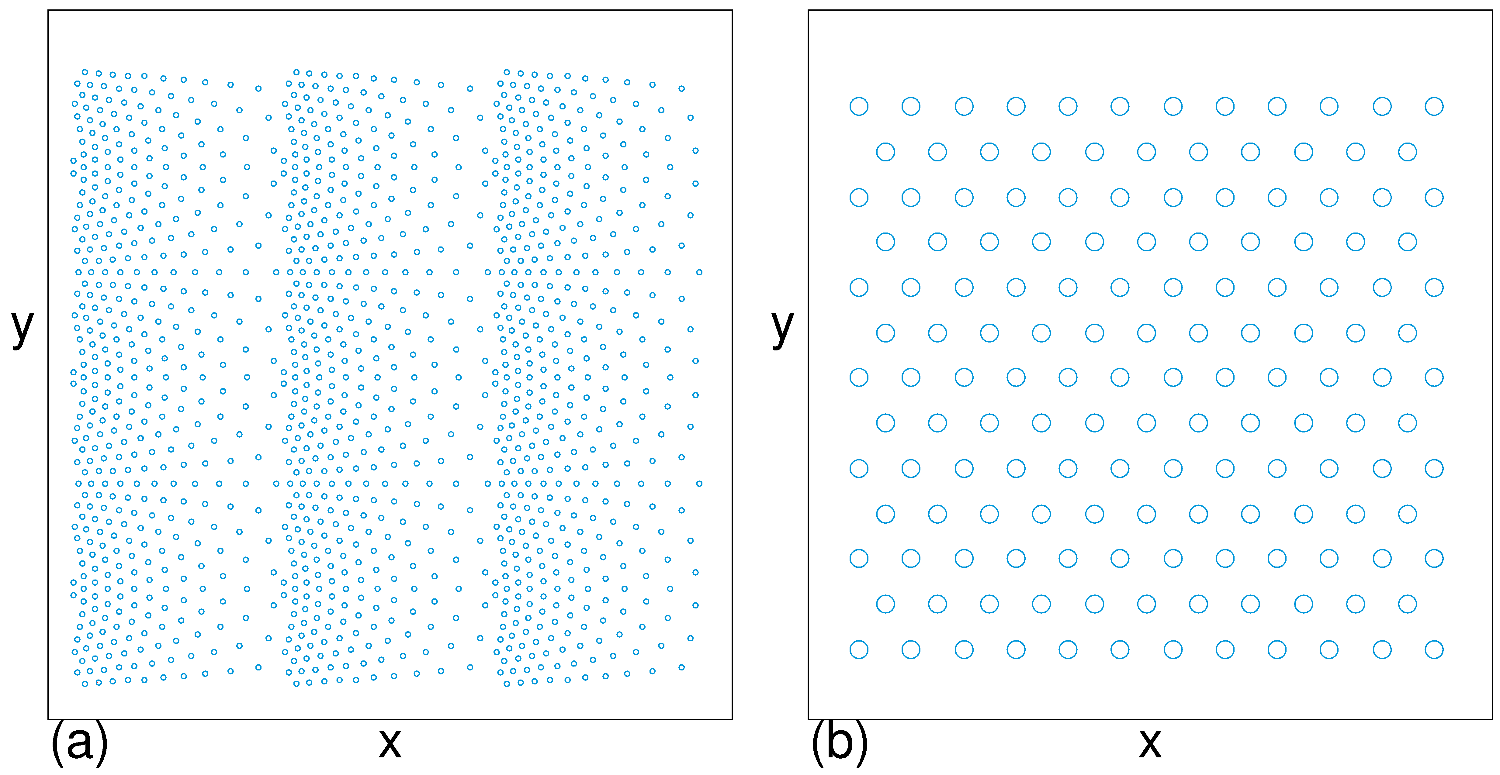
A conformal pinning array can be created by conformally transforming a uniform triangular pinning lattice to produces a new structure in which the six-fold ordering of the original lattice is conserved but where there is a spatial gradient in the density of pinning sites. Here we examine several aspects of vortices interacting with conformal pinning arrays and how they can be used to create a flux flow diode effect for driving vortices in different directions across the arrays. 
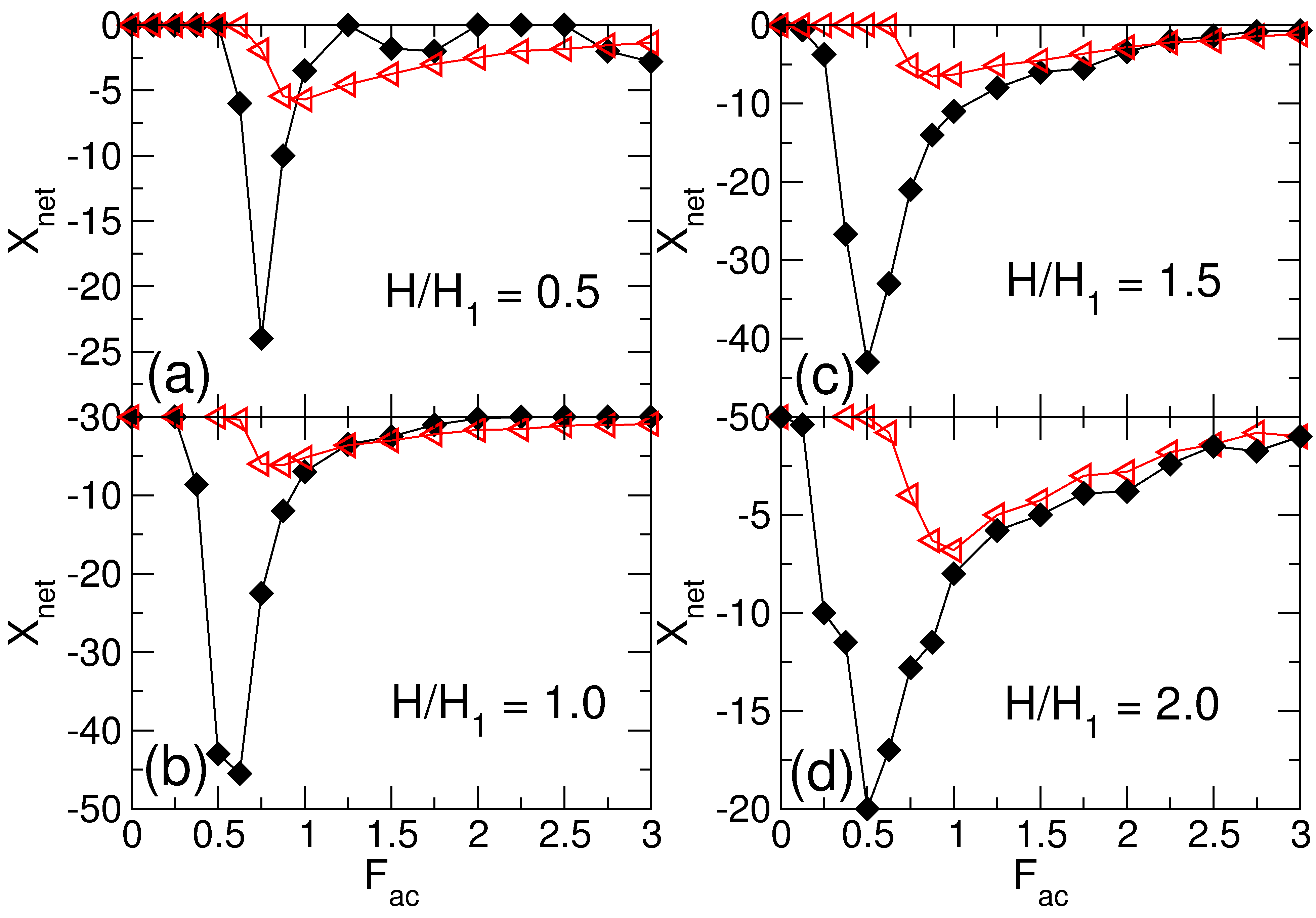
Under the application of an ac drive, a pronounced vortex ratchet effect occurs where the vortices flow in the easy direction of the array asymmetry. When the ac drive is applied perpendicular to the asymmetry direction of the array, it is possible to realize a transverse vortex ratchet effect where there is a generation of a dc flow of vortices perpendicular to the ac drive due to the creation of a noise correlation ratchet by the plastic motion of the vortices. 
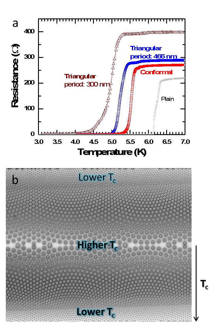
We also examine vortex transport simulations in experiments and compare the pinning effectiveness of conformal arrays to uniform triangular pinning arrays. 
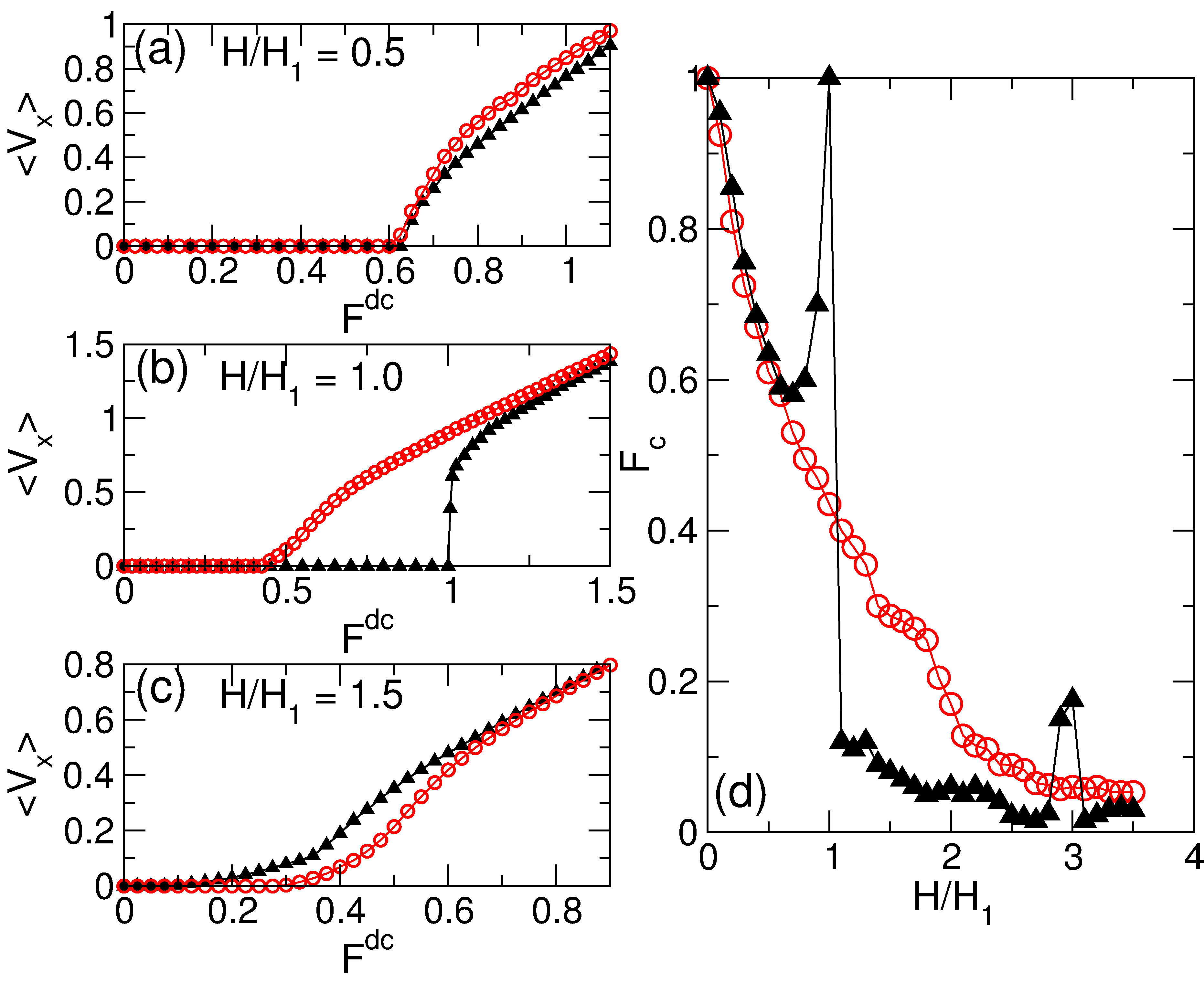
We find that a triangular array generally pins the vortices more effectively at the first matching field and below, while the conformal array is more effective at higher fields where interstitial vortex flow occurs.


1. Introduction
2. Simulations
3. Diode effect
4. Longitudinal and transverse ratchets
5. Pinning effects
6. Sample fabrication
7. Experimental results
8. Conclusion
References

1.  Introduction

Due to advances in nano-fabrication techniques it is possible to create a variety of vortex pinning array geometries in type-II superconductors. These include square [1,2,3,4,5,6], triangular [7,8,9], rectangular [10,11,12], honeycomb [13,14], spin ice [15,16], quasiperiodic [17,18,19,20] and other geometries [21,22]. In these systems a rich variety of novel vortex crystalline states can form, and there can be transitions between commensurate and incommensurate states as a function of vortex density. Another motivation to create such arrays is to identify optimal pinning arrangements that can produce the highest critical currents or allow for controlled vortex motion for fluxonic devices.
Recently a new type of pinning geometry was proposed called a conformal crystal [23,24]. It is constructed by applying a conformal transformation to a uniform triangular array of points to obtain a new structure in which the six-fold triangular ordering is preserved but where there is a spatial gradient in the density of pinning sites [25]. Such arrays potentially have interesting properties for enhancing pinning since vortex-vortex interactions naturally favor a triangular ordering, while an increasing magnetic field causes the vortices to naturally adopt a density or Bean gradient [26,27]. There are conditions where the conformal array is not as optimal as uniform triangular arrays, such as at integer matching fields where the gradient in the conformal arrays can prevent formation of a completely commensurate state. Initial simulations showed that conformal pinning arrays produced enhanced pinning compared to uniform random arrays, random arrays with a gradient, and periodic pinning arrays at non-matching fields, particularly at fields where there are more vortices than pinning sites [23,24]. Experiments indicated that the triangular pinning arrays produced stronger pinning than the conformal arrays below the first matching field, while the conformal pinning array generated stronger pinning at higher fields [28]. Other experiments also found enhanced pinning by conformal arrays [29], and there have also been other studies of pinning arrays with spatial gradients [30,31]. In further simulations where a series of conformal arrays were placed back to back as illustrated in Fig. 1, a pronounced vortex ratchet effect occurs when an ac drive is applied in the direction of the asymmetry of the array [32]. The ratchet effect in the conformal arrays is substantially stronger than that for random gradient arrays and square arrays with a one-dimensional (1D) spatial gradient that have the same number of pinning sites [32].
Fig1.png
Figure 1: Simulation pinning geometries (a) Three conformal crystal pinning arrays placed so as to produce a density asymmetry along the x-direction. (b) An example of a uniform triangular pinning array.
Here we highlight several aspects of vortex dynamics and pinning in conformal arrays. We show that a flux motion diode effect can occur in which the pinning is more effective for driving along one direction of the array. The conformal arrays also exhibit a strong anisotropy and have a much higher depinning force for motion along the asymmetry or x direction than for motion perpendicular to the asymmetry of the array. We demonstrate that a longitudinal rocking ratchet effect occurs when an ac drive is applied along the asymmetry direction, and that a novel transverse vortex ratchet effect can occur when the ac drive is applied perpendicular to the asymmetry. The transverse ratchet effect, which is weaker than the longitudinal ratchet effect, is an example of a noise correlation ratchet, rather than a rocking ratchet which occurs for the longitudinal driving. We show that the effectiveness of the pinning is stronger for uniform triangular arrays at low fields when interstitial vortices are absent, while the pinning is more effective in conformal arrays when interstitial vortices are present.

2.  Simulations

We consider a two-dimensional sample with periodic boundary conditions in the x and y-directions, and apply the external magnetic field H in the z) direction. In our current driven simulations, the initial vortex positions are obtained by simulated annealing. The vortex dynamics are governed by the following overdamped equation of motion:
η d Ri

dt
= Fvvi + Fvpi + Fdc + Facx,y .
(1)
Here η is the damping constant. The repulsive vortex-vortex interaction is Fvvi = ∑jiF0K1(Rij/λ)Rij, where K1 is a modified Bessel function, Ri is the location of vortex i, λ is the London penetration depth, Rij = |RiRj|, Rij = (RiRj)/Rij, F0 = ϕ20/(2πμ0λ3), ϕ0 is the flux quantum, and μ0 is the permittivity.
The system contains Np non-overlapping pinning sites each modeled as a parabolic potential with a range of Rp = 0.25λ. The pinning force has the form F i = (FpR(p)ik/rp)Θ((rpR(p)ik)/λ)R(p)ik, where Θ is the Heaviside step function, Fp is the maximum pinning force, Rk(p) is the location of pinning site k, Rik(p) = |RiRk(p)|, and Rik(p) = (RiRk(p))/Rik(p). All forces are measured in units of F0 and lengths in units of λ.
The creation of the conformal pinning geometry is described in [23,24]. Fig. 1(a) shows the pinning geometry with 3 back-to-back conformal arrays with a periodicity of 12λ. Fig. 1(b) shows a representative triangular pinning array; the array we simulate contains the same number of pinning sites as the conformal geometry in Fig. 1(a). The term Fdc represents a dc driving force, and we measure the dc velocity per vortex 〈V〉. The ac driving force term is Facx,y = Fx,yacsin(ωT)(x,y), where Fx,yac is the ac amplitude. We consider both Fxac where the ac drive is applied in the x direction parallel to the array asymmetry, as well as Fyac where the ac drive is applied in the y direction perpendicular to the array asymmetry, and measure longitudinal and transverse vortex ratchet effects. To quantify the ratchet effects, we measure the sum of the displacements in the direction of the asymmetry of the array, Xnet = N−1vNvi=1(xi(t) − xi(t0)), where xi(t) is the position of vortex i at time t and xi(t0) is the initial position of the vortex when the ac driving is first applied. We measure the value of Xnet after 25 ac drive cycles to avoid any transient effects.

3.  Diode effect

Fig2.png
Figure 2: (a-c) The average vortex velocity |〈Vx〉| in the conformal array from Fig. 1(a) with Fp = 1.0 for driving in the −x direction (open squares) and in the +x direction (filled circles). (a) At H/H1 = 0.5, the transport curves are asymmetric. (b) At H/H1 = 1.0 the asymmetry is larger. (c) At H/H1 = 1.5 the asymmetry is still present. (d) The velocity in the y-direction 〈Vy〉 for driving in the +y direction of the conformal array (triangles), plotted with 〈Vx〉 for driving in the +x direction (filled circules) at H/H1 = 1.0, showing anisotropic transport and a crossing of the velocity force curves.
In Fig. 2(a,b,c) we plot the absolute value of |〈Vx〉| versus Fdc for the conformal array in Fig. 1(a) with Fp = 1.0 at different fields H/H1, where H1 is the first matching field. The squares denote dc driving in the negative x or easy flow direction, and circles denote dc driving in the positive x or hard direction of the array. For H/H1 < 0.2 there is no difference in the depinning threshold for driving in either direction. At these low fields, the system is in the single vortex limit, and since Fp is symmetric for an individual pinning site, the depinning is also symmetric in this limit. At H/H1 = 0.5 in Fig. 2(a), there is an asymmetry in the transport and the vortices depin at a lower value of Fdc for driving in the −x-direction. At H/H1 = 1.0 in Fig. 2(b), this depinning asymmetry is enhanced, and within the moving phases the vortex velocities are lower for driving in the +x direction. This aymmetry gradually disappears for higher Fdc > Fp. The asymmetry persists up to higher values of H/H1 as shown in Fig. 2(c) at H/H1 = 1.5. The diode effect we observe arises due to collective vortex interactions. It differs from other previously reported diode effects for vortices interacting with asymmetric substrates such as quasi-1D saw-tooth potentials, where the pinning forces have an intrinsic asymmetry so that a diode effect appears even in the single vortex limit [33,34].
The conformal arrays also exhibit anisotropic transport for driving along different directions. In Fig. 2(d) we plot 〈Vy〉 versus Fdc for a dc drive applied in the +y-direction for the system in Fig. 1(a) at H/H1 = 1.0, along with 〈Vx〉 for driving in the +x direction. The +y depinning force is significantly lower than the +x depinning force; however, a crossing of the velocity-force curves occurs near Fdc = 0.5, above which the average vortex velocity for y-direction driving becomes lower than that for x-direction driving. The lower +y depinning threshold arises because vortices can more easily depin in the low pinning density regions of the sample. As Fdc increases for +y driving, the widths of the regions in which vortex motion is occurring increases until Fdc > 1.0, when all the vortices are moving. In contrast, for +x driving, the vortices cannot move until they are able to pass through the most densely pinned regions of the sample, so that there is a transition from no vortices moving to all vortices moving, which produces a higher net average velocity.

4.  Longitudinal and transverse ratchets

The asymmetry of the conformal arrays makes it possible to realize a ratchet effect by applying an ac driving force along the direction of the array asymmetry to produce a net dc motion of vortices. Previous vortex ratchet studies focused on cases in which the pinning substrates or individual pining sites have an intrinsic asymmetry, such as a quasi-1D sawtooth potential [33,34,35], funnel geometries [36,37], arrays of triangular pinning sites [38,39,40], and other geometries with asymmetrically shaped pinning sites [41,42,43]. Vortex ratchets have also been studied in systems with random pinning gradients [44] as well as periodic lattices with 1D gradients [45]; however the ratchet effects for the conformal arrays are generally more pronounced than for these systems [32].
Fig3.png
Figure 3: Xnet, the particle displacements in the x-direction after 25 ac drive cycles, for the conformal array at Fp = 1.0 for ac driving in the x-direction (filled diamonds) and ac driving in the y-direction (open triangles), showing both the longitudinal and transverse ratchet effect, at H/H1 = (a) 0.5, (b) 1.0 (c), 1.5 and (d) 2.0.
In Fig. 3(a) we plot the net vortex displacements Xnet after 25 ac drive cycles versus ac drive amplitude for the conformal system with driving in the x− or y− direction for Fp = 1.0 and H/H1 = 0.5. The net displacement is in the −x or easy flow direction of the substrate. For the longitudinal drive there is a maximum in the ratchet efficiency near Fxac = 0.7 where the vortices move an average of Xnet=25λ. For Fxac > 1.0 the ratchet effect persists but gradually disappears at the highest drives. When the ac drive is applied in the y-direction, Fig. 3(a) shows that there is still a net drift of vortices in the −x-direction, indicating the appearance of a transverse ratchet effect in which an ac drive produces a net dc motion of particles in the direction perpendicular to the drive. Transverse ratchets have been studied for vortices interacting with triangular shaped pinning sites, where the vortices are geometrically deflected by the pinning site asymmetry [39,46]. In the conformal array, the pinning sites are symmetric, so the transverse ratchet effect arises from a different process. Under a y-direction ac drive, the vortices undergo plastic motion through the conformal array, so that in a co-moving frame the vortices experience fluctuations in both the x- and y-directions. Previous studies have shown that plastically flowing vortices exhibit strong non-Gaussian or colored noise fluctuations [47,48] which, unlike white noise, are time correlated. It is known that if a particle is placed in an asymmetric substrate and exposed to time-correlated fluctuations, it will behave as a noise ratchet [49]. In the vortex system, the fluctuations do not arise directly from a fluctuating noise term in the equations of motion, but instead originate in the collective dynamics generated by the plastic flow of the vortices. Previous studies of interacting particles in a quasi-1D sawtooth substrate with added random quenched disorder showed that the system can exhibit a transverse drift when a dc drive is applied in the direction perpendicular to the substrate asymmetry [50]. The transverse ratchet is generally weaker than the longitudinal ratchet; however, there are regimes in which the transverse ratchet effect is comparable to or even stronger than the longitudinal ratchet effect. In Fig. 3(b) we show that at H/H1 = 1.0, the magnitude of the longitudinal ratchet is larger than at the lower field of H/H1 = 0.5. The transverse ratchet becomes more effective than the longitudinal ratchet for Fac > 1.5. At H/H1 = 1.5 in Fig. 3(c) both ratchets effects are present, and in general, the maximum efficiency of the longitudinal ratchet decreases with increasing H/H1 while the transverse ratchet efficiency remains almost constant, as shown in Fig. 3(d) at H/H1 = 2.0.

5.  Pinning effects

Fig4.png
Figure 4: (a,b,c) 〈Vx〉 vs Fdc for driving in the +x direction in the conformal array (open circles) and a triangular array (filled triangles) with the same number of pinning sites at H/H1= (a) 0.5, (b) 1.0, and (c) 1.5. (d) The depinning force Fc vs H/H1 for driving in the +x direction in the conformal array (open circles) and triangular array (filled triangles).
We next compare the dc depinning of the conformal array to that of a uniform triangular array of the type shown Fig. 1(b) with the same number of pinning sites at Fp = 1.0. Previous computational studies focued on the case of flux gradient driven dynamics, where the pinning efficiency was determined by measuring the width of the magnetization hysteresis loops [23,24]. Here we study vortex transport with a current driven simulation in which there is no induced flux gradient, and we still find strong differences in the vortex depining for the two cases. At low fields of H/H1 ≤ 0.5, the system behaves in the single vortex limit and the depinning threshold force Fc is the same for the triangular and conformal arrays, as shown in Fig. 4(a) where we plot 〈Vx〉 versus Fdc for driving in the positive x direction for both arrays at H/H1=0.5. For 0.5 < H/H1 ≤ 1.0, Fc is higher for the triangular pinning array as shown in Fig. 4(b) at H/H1=1.0. Close to H/H1 = 1.0, the vortices in the triangular pinning array form a commensurate structure in which every pinning site is occupied so that the vortex-vortex interactions effectively cancel and the depinning threshold is Fc = Fp, while in conformal array only a portion of the pinning sites are occupied due to the pining gradient so that the depinning force is less than half of that of the triangular pinning array. For H/H1 > 1.0, interstitial vortices appear in the triangular pinning array and cause a sharp drop in the depinning threshold, while Fc for the conformal array remains nearly unchanged and is now higher than that of the triangular array, as illustrated in Fig. 4(c) at H/H1 = 1.5. In Fig. 4(d) we plot Fc versus H/H1 for the conformal and triangular arrays. Fc is higher for the triangular array around the matching peaks of H/H1 = 1.0 and H/H1=3.0. For H/H1 > 1.0 there is a rapid drop in Fc for the triangular array, and Fc does not increase again until an ordered commensurate state forms at H/H1 = 3.0 [3]. We note that the triangular array has only a weak peak in Fc at H/H1 = 2.0, where the vortices form a honeycomb state rather than a more stable triangular lattice [3]. For higher values of Fp, the differences between the two systems is reduced as the vortex-vortex interactions become less important and the system transitions to the single vortex pinning regime. In addition, the drop in Fc for the triangular arrays shifts to higher values of H/H1 when the pinning sites are strong enough or large enough to allow for double or multiple vortex occupancy.

6.  Sample fabrication

Fig5.png
Figure 5: Patterning-induced degradation of superconducting critical temperature. (a) R-T curves of focused-ion-beam (FIB) patterned MoGe films with various hole patterns (two triangular arrays and a conformal array) and that of a reference plain film. The hole sizes in the various patterns are all around 100 nm. The spacing of the two triangular arrays are 300 nm and 466 nm, respectively. The Tc is suppressed in the patterned sections as compared to the unpatterned plain film and further decreases with shorter hole-hole spacing. The conformal hole array has equivalent average hole density with the triangular hole array with 466 nm hole-hole spacing and it shows higher Tc than the triangular array due to the low density of holes in the center part of the film. (b) Non-uniformly distributed Tc in conformal hole array.
In fabricating samples for measurement, we observe that Tc of the sample is usually suppressed due to processing-induced sample degradation. Figure 5(a) shows the R-T curves of a plain MoGe film, two focus-iron-beam (FIB) patterned MoGe films containing a triangular array of holes with different hole-hole spacings, and one FIB patterned MoGe film with a conformal array of holes having an equivalent average hole density as one of the triangular arrays. All three patterned films have lower Tc values than the unpatterned film, indicating processing-induced degradation of superconductivity. Furthermore, the film with a hole-hole spacing of 300nm has a lower Tc than that with a hole-hole spacing of 460 nm. That is, when holes are patterned with a process that can obviously degrade the sample, the sample with a higher density of holes will have a lower Tc. For a non-uniform pinning geometry, such as the conformal pinning array, the Tc of the sample is spatially inhomogeneous because the hole-hole spacings vary across the sample. That is, the region with a higher local density of pinning sites has smaller Tc, as shown in Fig. 4(b). The Tc determined from the transport measurements gives values from the current channels that have the highest Tc, resulting in an over-estimate of the true Tc.
Samples with different pinning geometries usually have different Tc values due to the patterning-induced sample degradation, which confounds the comparison of different pinning landscapes. One commonly used method for comparing the results from samples with different Tc is to compare data obtained at the same reduced temperature T/Tc. Due to the non-uniformly distributed Tc in non-uniform pinning geometries, however, the reduced temperature T/Tc determined by the transport method is nearly meaningless. Thus, when studying non-uniformly distributed pinning geometries, it is important to adopt a sample fabrication method that limits the damage only to the holes and that does not alter the Tc of the rest of the sample.
These Tc suppressing effects are frequently observed in FIB patterned samples and samples fabricated using direct liftoff method. Our sample patterning method of using E-beam lithography followed by reactive ion etching does not suppress the Tc of the films [28]. The film is protected by an E-beam resist mask during the etching process and there is no damage to the film except for the area of the hole, which not only enables us to measure and compare the results at the same temperature but also produce holes with a strong pinning potential.

7.  Experimental results

Fig6.png
Figure 6: Pinning performances of a conformal pinscape and a triangular pinscape. (a) Critical currents of three sections on the same MoGe micro-bridge with one section patterned with a triangular array of holes (hole-hole spacing: 446 nm), one section patterned with a conformal array of holes (containing an equivalent average density of holes as the triangular array) and one un-patterned reference section. (b) I-V curves at magnetic fields of 0.8H1 (left panel) and 3H1 (right panel). The data of the three sections are measured at the same time and temperature. The Tc of the sample is 6.16 K and the measured temperature is 5.6 K (91% Tc).
Figure 6(a) shows the magnetic field dependence of the critical current Ic(H) for three sections on the same micro-bridge of a superconducting MoGe film measured at the same time and temperature (T = 5.6 K). The hole size is about 110 nm which ensures that each hole can only trap one vortex while additional vortices occupy the interstitial spaces between holes. Both of the two patterned sections have significantly enhanced critical currents compared to the unpatterned reference section at all applied magnetic fields, indicating the pinning effectiveness of the fabricated hole-arrays. For the triangular pinning array, the steep drop of the critical current curve once the magnetic field exceeds the first matching value is due to the appearance of interstitial vortices, which can be depinned at a much lower driving force in a regular pinning array with easy vortex flow channels. Above the first matching field, the depinning of the weakly pinned interstitial vortices makes the third and fourth matchings almost indistinguishable. On the other hand, a small peak appears at the fifth matching field due to a caging effect of the interstitial vortices. The Ic(H) curve (red) in Fig. 6(a) for the section with a conformal hole array shows a smooth decay in the critical current with increasing magnetic field. The gradually changing hole density produces localized commensuration at a series of local matching fields, which smears out the bulk matching field features. Although these multiple matching length scales can result in pinning enhancement over a wide range of magnetic field, the incommensuration between the conformal array and an Abrikosov triangular lattice leads to an increase in the vortex-vortex interaction energy in the vortex matter, thus reducing the critical current compared to the triangular hole array, which is perfectly commensurate with the Abrikosov triangular lattice at magnetic fields lower than the first matching field. Once interstitial vortices appear above the first matching field, however, the conformal hole array outperforms its triangular array counterpart in pinning efficiency. The pinning performance of different pinning arrays can also be observed in the I-V curves shown in Fig. 6(b). At the low field H/H1=0.8, the zero resistance state persists to a higher current for the triangular pinning array, while at the high field H/H3=3, the conformal pinning array maintains zero resistance over a larger current range.
Fig7.png
Figure 7: Comparison of critical currents. Ratios of the critical currents for the sections with conformal (Ic(Con)) and triangular (Ic(Tri)) hole arrays of three samples with different hole spacing b (average), hole diameters/sizes d and hole types (through or blind). Sample I: b=777 nm, d=220 nm, through holes; Sample II: b=466 nm, d=110 nm, through holes; Sample III: b=466 nm; d=110 nm, blind holes.
We compare the pinning effect of the conformal and triangular hole arrays of three different samples in Fig. 7 by plotting the magnetic field dependence of the ratios of their critical currents. Sample I and Sample II contain through holes with strong pinning strength for each individual hole. They have different hole sizes. Sample I has bigger holes (220 nm in diameter), each of which can trap up to two vortices at the measured temperature. In this sample the performance of the conformal pinning array surpasses that of the triangular pinning array at fields above the second matching field. Sample II has smaller holes (110 nm in diameter), each of which can trap at most one vortex, so the performance of the conformal pinning array surpasses that of the triangular pinning array above the first matching field. Sample III also has small holes that are 110 nm in diameter, but instead of through holes, sample III has blind holes with a much weaker pinning strength for each individual hole. The performance of the conformal pinning array also surpasses that of the triangular pinning array above the first matching field. Due to the weaker pinning strength of the holes, the advantage of the conformal pinning array in sample III at high fields is not as obvious as in sample II. In all three samples, the critical currents of the sections containing conformal hole arrays are lower than those of the sections with holes arranged in a triangular lattice at low magnetic fields (H < 2H1 for Sample I, H < H1 for Samples II and III) where all vortices are pinned in the triangular lattice of holes. At high magnetic fields the conformal array enhances the critical currents in all three samples except for Sample III which has blind holes and weak pinning strength. In this case, in a specific field range (around the third matching field in Sample III), the caging effect of the triangular lattice prevails.

8.  Conclusion

We have investigated various aspects of vortex motion and pinning in conformal pinning arrays using both simulations and experiments. For dc driving in the direction the asymmetry of the pinning array we find that there is a diode effect where the effective pinning is higher in the hard direction of the asymmetry of the array. This pinning asymmetry is a collective effect since in the single vortex limit the diode effect is absent as the pinning sites themselves are symmetric. In the presence of an ac drive in the same direction as the asymmetry of the array, a pronounced longitudinal vortex ratchet effect can occur. We also show that when the ac drive is applied perpendicular to the array asymmetry direction, a transverse vortex ratchet occurs in which there is a net dc flow of vortices perpendicular to the ac drive. The longitudinal ratchet is a realization of of a collective rocking ratchet while the transverse ratchet is an example of a noise correlation ratchet. The confomral pinning arrays in general show enhanced pinning over uniform triangular pinning arrays when the external field is large enough that interstitial vortices are present, while at fields where commensurate vortex lattice structures occur, the pining is higher in the triangular pinning arrays.
This work was carried out under the auspices of the NNSA of the U.S. DoE at LANL under Contract No. DE-AC52-06NA25396.

 References

[1]
M. Baert, V.V. Metlushko, R. Jonckheere, V.V. Moshchalkov, and Y. Bruynseraede, Phys. Rev. Lett. 74 (1995) 3269.
[2]
K. Harada, O. Kamimura, H. Kasai, T. Matsuda, A. Tonomura, and V.V. Moshchalkov, Science 274 (1996) 1167.
[3]
C. Reichhardt, C. J. Olson, and F. Nori, Phys. Rev. B 57 (1998) 7937.
[4]
V. Metlushko, U. Welp, G. Crabtree, Z. Zhang, S. Brueck, B. Watkins, L. DeLong, B. Ilic, K. Chung, and P. Hesketh, Phys. Rev. B 59 (1999) 603.
[5]
A.N. Grigorenko, S.J. Bending, M.J. Van Bael, M. Lange, V.V. Moshchalkov, H. Fangohr, and P.A.J. de Groot, Phys. Rev. Lett. 90 (2003) 237001.
[6]
G.R. Berdiyorov, M.V. Milosevic, and F.M. Peeters, Phys. Rev. Lett. 96 (2006) 207001.
[7]
J.I. Martín, M. Vélez, J. Nogués, and I.K. Schuller, Phys. Rev. Lett. 79 (1997) 1929.
[8]
U. Welp, Z.L. Xiao, V. Novosad, and V.K. Vlasko-Vlasov, Phys. Rev. B 71 (2005) 014505.
[9]
S. Goldberg, Y. Segev, Y. Myasoedov, I. Gutman, N. Avraham, M. Rappaport, E. Zeldov, T. Tamegi, C.W. Hicks, and K.A. Moler, Phys. Rev. B 79 (2009) 064523.
[10]
C. Reichhardt, G.T. Zimányi, and N. Grønbech-Jensen, Phys. Rev. B 64 (2001) 014501.
[11]
G. Karapetrov, J. Fedor, M. Iavarone, D. Rosenmann, and W.K. Kwok, Phys. Rev. Lett. 95 (2005) 167002.
[12]
M. Vélez, J.I. Martín, J.E. Villegas, A. Hoffmann, E.M. González, J.L. Vicent, and I.K. Schuller, J. Mag. Mag. Mater. 320 (2008) 2547.
[13]
C. Reichhardt and C. J. Olson Reichhardt, Phys. Rev. B 76 (2007) 064523.
[14]
M.L. Latimer, G.R. Berdiyorov, Z.L. Xiao, W.K. Kwok, and F. M. Peeters, Phys. Rev. B 85 (2012) 012505.
[15]
A. Libál, C. J. Olson Reichhardt, and C. Reichhardt, Phys. Rev. Lett. 102 (2009) 237004.
[16]
M.L. Latimer, G.R. Berdiyorov, Z.L. Xiao, F.M. Peeters, and W.K. Kwok, Phys. Rev. Lett. 111 (2013) 067001.
[17]
V. Misko, S. Savel'ev, and F. Nori, Phys. Rev. Lett. 95 (2005) 177007.
[18]
M. Kemmler, C. Gürlich, A. Sterck, H. Pöhler, M. Neuhaus, M. Siegel, R. Kleiner, and D. Koelle, Phys. Rev. Lett. 97 (2006) 147003.
[19]
A.V. Silhanek, W. Gillijns, V.V. Moshchalkov, B.Y. Zhu, J. Moonens, and L.H.A. Leunissen, Appl. Phys. Lett. 89 (2006) 152507.
[20]
C. Reichhardt and C.J. Olson Reichhardt, Phys. Rev. Lett. 106 (2011) 060603.
[21]
C. Reichhardt and C. J. Olson Reichhardt, Phys. Rev. B 76 (2007) 094512.
[22]
M. Kemmler, D. Bothner, K. Ilin, M. Siegel, R. Kleiner, and D. Koelle, Phys. Rev. B 79 (2009) 184509.
[23]
D. Ray, C. J. Olson Reichhardt, B. Jankó, and C. Reichhardt, Phys. Rev. Lett. 110 (2013) 267001.
[24]
D. Ray, C. Reichhardt, and C. J. Olson Reichhardt, Phys. Rev. B 90 (2014) 094502.
[25]
P. Pieranski, in Phase Transitions in Soft Condensed Matter, edited by T. Riste and D. Sherrington (Plenum, New York, 1989), p. 45; F. Rothen, P. Pieranski, N. Rivier, and A. Joyet, Eur. J. Phys. 14 (1993) 227. F. Rothen and P. Pieranski, Phys. Rev. E 53 (1996) 2828.
[26]
C. P. Bean, Phys. Rev. Lett. 8 (1962) 250; Rev. Mod. Phys. 36 (1964) 31.
[27]
C. Reichhardt, C.J. Olson, J. Groth, S. Field, and F. Nori, Phys. Rev. B 52 (1995) 10441.
[28]
Y.L. Wang, M.L. Latimer, Z.L. Xiao, R. Divan, L.E. Ocola, G.W. Crabtree, and W.K. Kwok, Phys. Rev. B 87 (2013) 220501.
[29]
S. Guenon, Y.J. Rosen, A.C. Basaran, and I.K. Schuller, Appl. Phys. Lett. 102 (2013) 252602.
[30]
V.R. Misko and F. Nori, Phys. Rev. B 85 (2012) 184506.
[31]
M. Motta, F. Colauto, W.A. Ortiz, J. Fritzsche, J. Cuppens, W. Gillijns, V.V. Moshchalkov, T.H. Johansen, A. Sanchez, and A.V. Silhanek, Appl. Phys. Lett. 102 (2013) 212601.
[32]
C. Reichhardt, D. Ray, and C.J. Olson Reichhardt, Phys. Rev. B 91 (2015) 184502.
[33]
C.S. Lee, B. Jankó, I. Derényi, and A.L. Barabási, Nature (London) 400 (1999) 337.
[34]
Q. Lu, C.J. Olson Reichhardt, and C. Reichhardt, Phys. Rev. B 75 (2007) 054502.
[35]
V.A. Shklovskij and O.V. Dobrovolskiy, Phys. Rev. B 84 (2011) 054515.
[36]
J.F. Wambaugh, C. Reichhardt, C.J. Olson, F. Marchesoni, and F. Nori, Phys. Rev. Lett. 83 (1999) 5106.
[37]
N.S. Lin, T.W. Heitmann, K. Yu, B.L.T. Plourde, and V.R. Misko, Phys. Rev. B 84 (2011) 144511
[38]
J.E. Villegas, S. Savel'ev, F. Nori, E.M. Gonzalez, J.V. Anguita, R. Garcia, and J.L. Vicent, Science 302 (2003) 1188.
[39]
C. J. Olson Reichhardt and C. Reichhardt, Physica C 432 (2005) 125.
[40]
A. Palau, C. Monton, V. Rouco, X. Obradors, and T. Puig, Phys. Rev. B 85 (2012) 012502.
[41]
R. Wördenweber, P. Dymashevski, and V.R. Misko, Phys. Rev. B 69 (2004) 184504.
[42]
C.C. de Souza Silva, J. Van de Vondel, M. Morelle, and V.V. Moshchalkov, Nature (London) 440 (2006) 651.
[43]
J. Van de Vondel, V.N. Gladilin, A.V. Silhanek, W. Gillijns, J. Tempere, J.T. Devreese, and V.V. Moshchalkov, Phys. Rev. Lett. 106 (2011) 137003.
[44]
C. J. Olson, C. Reichhardt, B. Jankó, and F. Nori, Phys. Rev. Lett. 87 (2001) 177002.
[45]
T.C. Wu, R. Cao, T.J. Yang, L. Horng, J.C. Wu, and J. Kolacek, Sol. St. Commun. 150 (2010) 280.
[46]
L. Dinis, D. Perez de Lara, E.M. Gonzalez, J.V. Anguita, J.M.R. Parrondo, and J.L. Vicent, New J. Phys. 11 (2009) 073046.
[47]
A.C. Marley, M.J. Higgins, and S. Bhattacharya, Phys. Rev. Lett. 74 (1995) 3029.
[48]
C.J. Olson, C. Reichhardt, and F. Nori, Phys. Rev. Lett. 80 (1998) 2197.
[49]
C.R. Doering, W. Horsthemke, and J. Riordan, Phys. Rev. Lett. 72 (1994) 2984.
[50]
A. Kolton, Phys. Rev. B 75 (2007) 020201.


File translated from TEX by TTHgold, version 4.00.
Back to Home