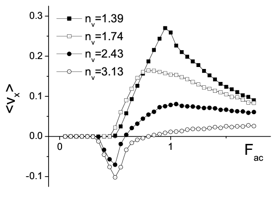
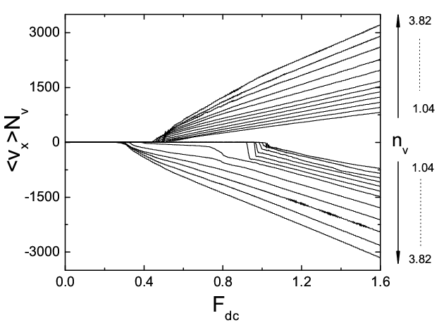
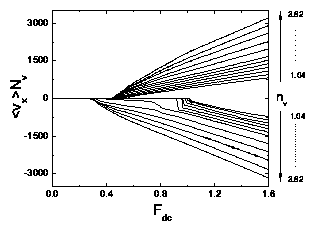
Physical Review B 75, 054502 (2007)

Reversible Vortex Ratchet Effects and Ordering in Superconductors with Simple Asymmetric Potential Arrays

Qiming Lu1,2, C.J. Olson Reichhardt1, and C. Reichhardt1

1 2

1Center for Nonlinear Studies and Theoretical Division, Los Alamos National Laboratory, Los Alamos, New Mexico 87545, USA
2Department of Physics, Applied Physics, and Astronomy, Rensselaer Polytechnic Institute, Troy, New York 12180-3590, USA

(Received 21 September 2006; revised manuscript received 3 December 2006; published 6 February 2007)

We demonstrate using computer simulations that the simplest vortex ratchet system for type-II superconductors with artificial pinning arrays, a simple asymmetric potential array, exhibits the same features as more complicated two-dimensional (2D) vortex ratchets that have been studied in recent experiments. We show that the simple geometry, originally proposed by Lee et al. [Nature 400, 337 (1999)], undergoes multiple reversals in the sign of the ratchet effect as a function of vortex density, substrate strength, and ac drive amplitude, and that the sign of the ratchet effect is related to the type of vortex lattice structure present. Thus, although the ratchet geometry has the appearance of being effectively 1D, the behavior of the ratchet is affected by the 2D structure of the vortex configuration. When the vortex lattice is highly ordered, an ordinary vortex ratchet effect occurs which is similar to the response of an isolated particle in the same ratchet geometry. In regimes where the vortices form a smectic or disordered phase, the vortex-vortex interactions are relevant and we show with force balance arguments that the ratchet effect can reverse in sign. The dc response of this system features a reversible diode effect and a variety of vortex states including triangular, smectic, disordered and square.
I. INTRODUCTION
II. SIMULATION
III. DC DEPINNING AND VORTEX LATTICE STRUCTURES
IV. RATCHET AND REVERSE RATCHET EFFECT
V. SUMMARY
References


I.  INTRODUCTION

When an overdamped particle is placed in an asymmetric potential and an additional ac drive is applied, a net dc drift velocity or rectification can occur which is known as the ratchet effect. Stochastic ratchets can be constructed with Brownian particles, while ordinary ratchets can be created in deterministic systems [1]. Typically, an applied ac drive or periodic flashing of the potential couples with some form of asymmetry in the substrate, breaking the symmetry of the particle motion. Ratchet effects have been studied in the context of molecular motors [1] as well as in the motion of colloidal particles [2], granular materials [3] and cold atoms in optical trap arrays [4].
Vortices in type-II superconductors act as overdamped particles moving in nanostructured potential landscapes. The possibility of realizing a ratchet effect to transport superconducting vortices was originally proposed by Lee et al. [5], who studied vortices interacting with a simple asymmetric or sawtooth substrate potential and an additional external ac drive. This type of asymmetric potential could be fabricated by creating a superconducting sample that has an asymmetric thickness modulation. The external ac drive is provided by either an oscillating external magnetic field or by an applied ac current which produces an oscillating Lorentz force on the vortices. The numerical simulations of Ref. [5] indicated that a net dc motion of vortices could arise upon application of an ac drive, and that the net vortex drift is in the easy direction of the asymmetric substrate, as would be expected for a single particle interacting with such a potential. The original work on vortex ratchets was followed by a series of proposals for alternative vortex ratchets based on 2D asymmetric pinning array geometries, each of which produces similar types of vortex ratchet effects with the net vortex flow in the easy direction of the underlying potential [6,7,8,9,10]. These ratchets operate either through a bottleneck effect [6,9] or by means of an effectively 1D mechanism [7,8,10]. Similar ratchet effects have also been found for superconductors with asymmetric surface barriers [11].
Recently, new types of 2D periodic pinning geometries have been proposed that exhibit not only the regular ratchet effect but also a reverse ratchet effect, in which the net dc vortex motion is in the hard substrate direction [12,13,14,15,16,17]. In some cases, ratchet reversals occur when the vortex-vortex interactions at higher fillings become relevant, resulting in an effective asymmetric potential oriented in the direction opposite to the pinning structure. As a result, some of the vortices move in the hard direction of the pinning substrate, and the net motion is described by either an effectively 1D [14,15,17] or 2D [16] mechanism. Other vortex ratchet systems have multiple sign reversals due to symmetry breaking from multiple circular ac drives [12] or three state pinning potentials [13]. The reverse vortex ratchet effect has been observed in experiments with 2D arrays of triangular pinning sites [15] and other types of 2D arrays [17]. In the work of Silva et al. [17], the periodic pinning array in the experimental sample has a two component unit cell containing a large pinning site with a small pinning site placed to one side. This system exhibits a remarkable field dependent multiple reverse ratchet effect. For the first matching field and higher odd matching fields, a regular ratchet effect occurs, but at even matching fields the ratchet effect changes sign. Simulations indicate that the pinning sites are capturing multiple vortices, and that this can change the direction of the asymmetric effective potential at every matching field, as described by a 1D model. A ratchet effect has also been observed in a Josephson-junction array structure which has spatial asymmetry [18]. Here, a diode effect occurs where the depinning field is higher in the hard direction. A ratchet and reversed ratchet effect are also seen for matching fields less than one.
Fig1.png
Figure 1: Schematic of the simulation geometry. Vortices are subjected to an applied current J=Jy which produces a driving force Fext=Fdcx or Facx, illustrated in the top portion of the figure. The bottom portion of the figure shows the periodic potential U(x) through which the vortices move. The width of the easy direction of the pinning potential is l+ and the width of the hard direction is l, where l+ > l and l++l=a, the pinning lattice constant.
In this work, we perform a detailed investigation of the simplest vortex ratchet system created by an asymmetric periodic modulation, which was originally shown to exhibit only an ordinary ratchet effect [5]. By considering magnetic fields much higher than those used in Ref. [5], where the effectively single vortex regime was studied, we show that this system can also exhibit ratchet sign reversals as a function of vortex density when the vortex interactions become relevant. Unlike the majority of previously studied vortex ratchets, the behavior of this system is determined by the detailed 2D structure of the vortex configuration, and cannot be explained in terms of a simple 1D model. We find that the dc response exhibits a reversible diode effect correlated with the regions where the ratchet effect reverses. The sign of the ratchet effect is shown to be related to the nature of the overall vortex lattice structure. At magnetic field densities where the vortex lattice has a more ordered or crystalline structure, the effective vortex interactions cancel or are reduced by the symmetry of the lattice, and the response is the ordinary ratchet effect as in the case of a single vortex. At fields where the vortex lattice is disordered or has an intrinsic asymmetry, the interactions between individual vortices become relevant and a portion of the vortices move in the easy direction of the pinning potential, resulting in a reversal of the sign of the ratchet effect which can be predicted from force balance arguments. In addition to the ratchet response of this system, we show that a rich variety of distinct vortex phases can be realized as a function of density, including crystalline, smectic, disordered and square phases. Commensuration effects also create oscillations in the critical depinning force which are distinct from those observed for two dimensional periodic pinning arrays.
Fig2.png
Figure 2: The dc non-normalized average velocity 〈VxNv vs Fdc for varied nv and both directions of dc drive. The curves for Fiext=xFdc have 〈VxNv ≥ 0, while the curves for Fiext=−xFdc have 〈VxNv ≤ 0. In order of increasing |〈VxNv|, the curves have nv=1.04/λ2, 1.22/λ2, 1.39/λ2, 1.56/λ2, 1.74/λ2, 1.91/λ2, 2.08/λ2, 2.43/λ2, 2.78/λ2, 3.13/λ2, 3.47/λ2, and 3.82/λ2. For nv < 2.08/λ2, the negative drive critical depinning force is larger than the positive drive critical depinning force, fc > fc+, but for nv ≥ 2.08/λ2, this reverses and fc < fc+.

II.  SIMULATION

We consider a 2D system of size Lx = Ly = 24λ, where λ is the London penetration depth, with periodic boundary conditions in the x and y directions. The sample contains Nv vortices interacting with an asymmetric substrate U(x) of period a=λ, illustrated schematically in Fig. 1. The vortex density nv=Nv/LxLy. A given vortex i obeys the overdamped equation of motion
η d Ri

dt
= Fvvi + Fsi + Fexti + FTi .
(1)
The damping constant η = ϕ02d/2πξ2ρN, where d is the sample thickness, ξ is the coherence length, ρN is the normal-state resistivity, and ϕ0=h/2e is the elementary flux quantum. The vortex-vortex interaction force is
Fvvi = Nv

ji 
f0 K1
rij

λ

^
r
 

ij 
(2)
Here rij=|rirj|, rij=(rirj)/rij, and ri(j) is the position of vortex i (j). Force is measured in units of f0 = ϕ20/2πμ0λ3, and time in units of τ = η/f0. K1(rij/λ) is the modified Bessel function which falls off exponentially for rij > λ. For computational efficiency, the vortex-vortex interaction force is cut off at 6λ. We have previously found that using longer cutoff lengths produces negligible effects [20]. The pinning potential is modeled as a sawtooth as shown in Fig. 1,
Fis=


1

2
Ap
^
x
 
if 0xi mod a < l+
Ap
^
x
 
if l+xi mod a < a.
Here, Ap=1.0f0 and xi=ri ·x. The width of the long or "easy" side of the pinning potential is l+=(2/3)a and the width of the short or "hard" side is l=(1/3)a such that l++l=a. The term Fexti in Eq. 1 is the force from a dc or ac external driving current. For the case of an applied dc drive, Fexti = Fdcx, where Fdc is increased from zero in increments of δFdc = 0.01 every 104 simulation time steps. For the case of an applied ac drive, FextiFacx, where the positive sign is used during the first half of each period τ and the negative sign is used during the second half period, resulting in a square wave centered about zero. The initial vortex configurations are obtained through simulated annealing, where we set Fiext=0 and apply a thermal force with the properties 〈FiT〉 = 0 and 〈FiT(t)FjT(t′)〉 = 2ηkB T δij δ(tt′). The simulated annealing begins at a high temperature FT=5.0 which is well above the melting temperature of the vortex lattice, and then FT is slowly reduced to zero. After annealing, we set FiT=0, apply a dc or ac drive, and measure the average velocity 〈Vx 〉 = 〈(Nv−1)∑i=0Nvvi ·x〉. For dc driving, we identify the critical currents in the positive and negative driving directions, fc+ and fc, which we define as the drive at which |〈Vx〉|=0.1f0.
Fig3.png
Figure 3: The depinning force curves vs nv for the system in Fig. 2 for driving in the negative direction, fc (black circles), and in the positive direction, fc+ (open circles). The diode effect reverses near nv=1.91/λ2 and nv=9.90/λ2. Several oscillations in the depinning force also occur.
Fig4.png
Figure 4: 〈Vx〉 versus Fdc curves for positive driving, Fiext=xFdc (upper dashed line), and negative driving, Fiext=−xFdc (lower solid line). (a) A sample with nv=8.68/λ2 showing a negative diode effect with fc < fc+. (b) A sample with nv=10.42/λ2 showing a positive diode effect with fc > fc+.
Fig5.png
Figure 5: (a) Vortex locations (black dots) and edges of the pinning troughs (black lines) in a 12λ×12λ subsection of a system with nv=1.04/λ2 and no applied drive. A single column of vortices is confined within each trough. (b) Corresponding structure factor S(k) for nv=1.04/λ2. Here and in other plots of S(k), we show a greyscale heightmap of S(kx,ky) with white values higher than dark values, and with the origin of coordinates at the center of the panel. kx is along the vertical axis, and ky is along the horizontal axis. (c) Vortex and pinning trough locations for a system with nv=2.08/λ2 and no applied drive. In some regions, the columns of vortices have buckled and a smectic type of ordering begins to appear. (d) S(k) for nv=2.08/λ2. (e) Vortex and pinning trough locations for a system with nv=3.47/λ2 and no applied drive. Each trough contains two columns of vortices. (f) S(k) for nv=3.47/λ2. A double smectic ordering appears, as indicated by the two prominent lines in S(k).

III.  DC DEPINNING AND VORTEX LATTICE STRUCTURES

We first compare the dc response of the system for driving in the positive (easy) and negative (hard) x direction. The top set of curves in Fig. 2 show 〈VxNv versus Fdc for Fiext=xFdc for samples with Nv ranging from nv=1.04/λ2 to 3.82/λ2. The bottom set of curves show 〈VxNv versus Fdc for the same samples with Fiext=−xFdc. A clear diode effect occurs for nv < 2.08/λ2 when the negative (hard) critical depinning force fc is larger than the positive (easy) critical depinning force fc+. Here, fc/f0 <~1, close to the value of the pinning force in the hard direction, while fc+/f0 ≈ 0.5, nearly the same as the easy direction pinning force. Thus, for nv < 2.08/λ2, the depinning force in each direction is primarily determined by the pinning substrate and the vortex-vortex interactions are only weakly relevant. A pronounced drop in fc from fc/f0 ≈ 1 to fc/f0 ≈ 0.4 occurs above nv=2.08/λ2. For nv > 2.08/λ2, the diode effect is reversed since now fc < fc+.
When nv=2.08/λ2, the negative depinning curve in Fig. 2 shows a clear two step depinning process with an initial depinning near Fdc = 0.45f0 followed by a second jump in 〈Vx〉 near Fdc=0.8f0. At the low first depinning threshold, only a portion of the vortices depin, while at the second threshold near Fdc=0.8f0, the entire lattice depins.
The values of fc+ and fc undergo changes as a function of nv that are difficult to discern in Fig. 2. In Fig. 3 we plot both fc+ and fc versus nv for systems with up to 7000 vortices and nv=12.15/λ2. There is a positive diode effect for nv < 1.91/λ2 when fc > fc+. The diode effect reverses for 1.91/λ2nv ≤ 9.90/λ2, where fc < fc+. A second reversal occurs for nv > 9.90/λ2, when fc+ drops back below fc. The high nv reversal is shown in more detail in Fig. 4, where we plot 〈Vx〉 versus Fdc for two different samples. In Fig. 4(a), at nv=8.68/λ2, fc < fc+ and we find a negative diode effect. The situation is reversed in Fig. 4(b) at nv=10.42/λ2, where fc > fc+ and a positive diode effect occurs.
Fig6.png
Figure 6: (a) Vortex locations (black dots) and edges of the pinning troughs (black lines) in a 12λ×12λ subsection of a system with nv=5.21/λ2 and no applied drive. Each trough captures two columns of vortices. (b) Corresponding S(k) for nv=5.21/λ2 showing evidence of smectic ordering. (c) Vortex and pinning trough locations for nv=6.94/λ2. The vortex configurations are disordered. (d) S(k) for nv=6.94/λ2 has a clear ring structure. (e) Vortex and pinning trough locations for nv=10.42/λ2. The vortices form a tilted square lattice. (f) S(k) for nv=10.42/λ2 shows four-fold peaks.
Fig. 3 indicates that fc+ and fc both undergo oscillations. A simple 1D picture for the vortex structure would predict maxima to appear in the depinning force at the commensurate fields at which an integer number of vortex rows fit inside each pinning trough, given by nv=n22, where n is an integer. We do observe a maximum in both fc+ and fc near nv=4.0/λ2, corresponding to the presence of two ordered commensurate vortex rows per channel. Although fc has a very broad plateau centered around nv=9.0/λ2 which could be interpreted as the n=3 matching field, the inadequacy of a simple 1D picture is indicated by the fact that for fc+, the corresponding maximum falls at the much lower field nv=7.81/λ2. For vortex densities just above and below each of the commensurate fields, the addition or subtraction of a small number of vortices does not change the number of rows in each trough but instead causes a disordering of the rows relative to one another, resulting in a smectic structure. This occurs because the shear modulus is smaller than the compression modulus of the rows. As larger numbers of vortices are added, the compression of each row grows until the rows begin to buckle. The buckling transition destroys the alignment perpendicular to the vortex rows, causing the vortex configuration to become more isotropically disordered. This is similar to the commensuration effects found for vortex lattices in multilayer systems [21]. In this case, the field is applied along the direction of the layers so that the vortices effectively interact with a potential that is periodically modulated in one dimension. These experiments found oscillations in the magnetization, which is proportional to the depinning force. The oscillations were also attributed to transitions in the vortex lattice structure from n chains per layer to n+1 chains per layer [21].
The vortex configuration for nv < 1.04/λ2 has only one column of vortices per pinning trough modulation, as illustrated in Fig. 5(a). The presence of triangular ordering in the vortex lattice is clearly indicated by the structure factor S(k),
S(k) = Nv−1
Nv

i=1 
exp(ik·ri)
2
 
,
(3)
plotted in Fig. 5(b). On average, the vortex-vortex interactions cancel along the x direction since the vortices are equally spaced a distance a apart in this direction. Near nv=2.0/λ2, a transition in the vortex configuration occurs in which the vortex columns begin to buckle, as shown in Fig. 5(c). Here, the vortex-vortex interactions along the x direction no longer cancel, and at points in the vortex columns where a buckled vortex is adjacent to the column, a vortex within the column experiences both the force from the pinning substrate, which has a maximum value of Ap, as well as an additional force from the buckled vortex, which has a maximum value of K1(a)f0. A simple estimate of the depinning force in a buckled region, fc,b gives fc,b = ApK1(a)f0 = 0.395f0, which is close to the value of fc shown in Fig. 2 for nv > 2.08/λ2. For values of nv just above the buckling onset, buckling occurs in only a small number of places that are widely separated. Vortices near the buckled locations depin at fc,b, while vortices outside of the buckled locations do not depin until Fdc is close to Ap. The result is the two stage depinning process shown in Fig. 2 for nv=2.08/λ2. As the vortex density is further increased above nv=2.08/λ2, the distance between buckled regions decreases, smearing out the two step depinning process.
For 1.91/λ2 < nv < 5.90/λ2, y direction spatial correlations in the vortex configurations are lost due to the buckling of the vortex columns, but the pinning substrate maintains the spatial correlations in the x direction, resulting in smecticlike vortex structures. This is illustrated in Fig. 5(c,d) for nv=2.08/λ2 and in Fig. 5(e,f) for nv=3.47/λ2. At nv=2.08/λ2 in Fig. 5(c), a second column of vortices begins to form in each pinning trough by means of a buckling transition, as previously discussed. The corresponding structure factor in Fig. 5(d) shows some smectic type smearing, indicating that the vortices are less correlated in the y-direction than in the x-direction. As Nv increases, the correlations in the y direction are further decreased, as seen in S(k) for nv=3.47/λ2 in Fig. 5(f). At this density, the vortex configuration shown in Fig. 5(e) indicates that there are two columns of vortices per trough, which is also reflected by the double band feature in S(k). At nv=5.21/λ2, shown in Fig. 6(a), the vortex configuration still has two columns of vortices in each pinning trough, and the two band feature in S(k) is more prominent, as illustrated in Fig. 6(b). As Nv increases further, the two column structure is destroyed and the vortex configuration becomes highly disordered in both the x and y directions, as seen at nv=6.94/λ2 in Fig. 6(c). Here S(k) has a ring structure, as shown in Fig. 6(d). The effect of the one-dimensional substrate can still be seen in the form of small modulations along kx in Fig. 6(d).
At nv=10.42/λ2, plotted in Fig. 6(e), a new commensurate crystalline structure appears where four vortices fit across the pinning trough at a 45° angle so that the overall vortex lattice symmetry is square. This is supported by the four prominent peaks that appear in S(k) in Fig. 6(f). There is a competition between minimizing the vortex-vortex interaction energy, which favors a triangular lattice, and maximizing the vortex-substrate interaction, which favors commensurate vortex configurations. Since the difference in energy between a triangular and square vortex lattice is quite small, the commensuration effect is favored at nv=10.42/λ2, and a square structure appears. Since the vortex lattice is symmetrical, the vortex-vortex interactions are strongly reduced and the depinning transition is similar to the case of nv < 1.91/λ2 where fc > fc+ and the vortices depin more readily in the easy direction. In this case, the depinning response is elastic, but since there are multiple vortex columns in each trough there is a pronounced distortion in the lattice when a dc force is applied, causing fc to be significantly lower than Ap.
Fig7.png
Figure 7: (Color online) Contour plot of 〈Vx〉 as a function of ac drive period τ (in units of simulation time steps) and ac drive amplitude Fac (in units of f0) for a system with nv=0.087/λ2.
As a function of vortex density, the system thus passes through a sequence of triangular, smectic, disordered, and square vortex arrangements. These results show similarities to studies performed on magnetic particles interacting with simple symmetric periodic modulated substrates, where crystalline, smectic, and partially disordered structures were observed as a function of particle density [19]. The double smectic phases and the square lattice that we find did not appear in the magnetic particle experiment since the relative particle densities considered in Ref. [19] were much lower than the relative vortex densities we use here. Additionally, the asymmetry in our potential substrate may help to stabilize certain phases that are not seen with simple symmetric potentials.

IV.  RATCHET AND REVERSE RATCHET EFFECT

We next examine the response when an external ac drive is applied. When the vortex density is low, the vortex-vortex interactions are negligible and the system responds in the single particle limit. In Fig. 7 we show a contour plot of the average velocity 〈Vx〉 obtained from simulations with nv=0.087/λ2 for varied ac period τ and ac amplitude Fac. A series of tongues where a positive ratchet effect occurs are clearly visible. At small τ, there is not enough time for the vortices to respond to the ac drive so there is no ratchet effect. Similarly, at low Fac, the vortices are unable to cross the potential barrier of the trough, and no rectification occurs. At intermediate values of τ and Fac, a ratchet effect can occur. In the first tongue, which falls at the lower left edge of Fig. 7, the vortices move by +a in the x direction during the positive half of the driving period, but do not move back during the negative half of the period, resulting in a net rectification. On the second tongue, vortices translate by +2a during the first half of the period and by −a during the second half of the period, again giving a net rectification. As τ and Fac increase, the ratchet effect on the nth tongue is characterized by motion of +na during the positive half period of the drive and motion of −(n−1)a during the negative half period of the drive. The tongue structure emerges since for some values of τ and Fac, vortices undergo equal translations during both halves of the driving period, leading to no net motion. The boundary of the nth tongue where ratcheting can occur is given by
τn = η nl+

FacF+
+ η (n − 1)l

Fac + F
(4)
The weak pinning force F+ associated with the trough side of length l+ is F+=−Ap/2 in our case, while the strong pinning force F associated with the trough side of length l is F=Ap. For the first tongue in Fig. 7, Eq. 4 predicts τ1 ∝ (Fac + Ap/2)−1, which matches the simulation results. The results in Fig. 7 and Eq. 4 agree well with the tonguelike features found in Ref. [5] as a function of τ and Fac. This confirms that at low vortex densities, an ordinary ratchet effect occurs where the vortices move in the easy direction.
Fig8.png
Figure 8: 〈Vx〉 vs nv for the system in Fig. 7 at fixed τ = 104 simulation steps for (black circles) Fac = 0.6f0 and (open circles) Fac = 0.4f0. Here both positive and negative ratchet effects occur as a function of vortex density.
Fig9.png
Figure 9: 〈Vx〉 vs Fac for the same system as in Fig. 8 for varied nv. Filled squares: nv=1.39/λ2; open squares: nv=1.74/λ2; filled circles: nv=2.43/λ2; open circles: nv=3.13/λ2. The positive ratchet effect is preceded by a negative ratchet effect for nv > 1.74/λ2.
We next consider the effect of increasing nv. Since the ratchet effect in Fig. 7 is enhanced for larger periods τ, we fix the period at τ = 104 simulation steps. In Fig. 8 we plot 〈Vx〉 versus nv for Fac = 0.6f0 and 0.4f0. For nv < 2.60/λ2, there is a positive ratchet effect for Fac = 0.6f0 and no ratchet effect for Fac = 0.4f0. For nv > 2.60/λ2 a negative ratchet effect occurs for Fac = 0.4f0, while the positive ratchet effect for Fac = 0.6f0 decreases in size and reverses to a negative ratchet effect near nv=3.65/λ2. For both values of Fac, the system passes through a maximum negative value of 〈Vx〉 just below nv=5.21/λ2. Above nv=5.21/λ2, 〈Vx〉 gradually increases back toward zero before crossing zero and reversing to a small positive ratchet effect near nv=10.42/λ2. The features in these curves appear to be correlated with the vortex lattice structures presented in Figs 5 and 6. At low nv, the vortices form a triangular or smectic structure with only a single column of vortices in each pinning trough, as in Fig. 5(a,b). In this case, since the symmetry of the vortex configuration cancels or strongly reduces the vortex-vortex interaction force, a positive ratchet effect occurs that is determined only by the pinning forces of the substrate. The onset of the negative ratchet effect corresponds to the appearance of buckling of the columns of vortices in the pinning troughs, as seen in Fig. 5(c,d). In the double smectic phase illustrated in Fig. 5(e,f) and Fig. 6(a,b), the negative ratchet effect persists. The gradual disappearance of the negative ratchet effect for nv > 5.21/λ2 in Fig. 8 is associated with the crossover from the double smectic state to the disordered state shown in Fig. 6(c,d). The small positive ratchet effect near nv=10.42/λ2 is correlated with the formation of the ordered square lattice as seen in Fig. 6(e,f).
In Fig. 9 we plot 〈Vx〉 versus Fac for a series of simulations performed at varied nv. For low nv ≤ 1.74/λ2, there is no ratchet effect until a threshold value of Fac is reached. 〈Vx〉 then increases to a peak value and gradually decreases with increasing Fac. For nv > 1.74/λ2, the threshold value of Fac above which a ratchet effect occurs is lower than for nv ≤ 1.74/λ2, and the initial ratchet effect is in the negative direction rather than the positive direction. As Fac is increased, the negative ratchet effect reverses to a positive ratchet effect.
Fig10.png
Figure 10: (Color online) A colorscale map of 〈Vx〉 as a function of Fac and nv. For low Fac there is no ratchet effect. At higher Fac there is a positive ratchet effect for low nv, a reversal to a negative ratchet effect for intermediate nv, and another reversal at high nv to a positive ratchet effect.
Figure 10 illustrates 〈Vx〉 in a contour plot as a function of Fac and nv. The positive and negative ratchet effect regimes are highlighted. For low Fac there is no ratchet effect, while for high Fac/f0 > 1.0 all ratchet effects are gradually reduced. The maximum positive ratchet effect occurs for Fac/f0 close to 1.0, the value of the pinning force in the strong direction. The positive ratchet effect for nv < 2.60/λ2 does not occur unless Fac/f0 > 0.5, which is the maximum pinning force in the weak direction. The negative ratchet effect appears for nv > 2.08/λ2 and extends up to nv=8.68/λ2, with the maximum negative rectification occurring for 3.47/λ2 < nv < 5.21/λ2 at 0.45 < Fac/f0 < 0.5. For nv > 9.72/λ2, a reentrant positive ratchet effect appears that is much weaker in amplitude than the positive ratchet effect region found for low nv. In general, the ratchet effect in either direction is reduced for increasing nv since the effects of the substrate are gradually washed out by the increasing vortex-vortex interaction forces. This result shows that vortices interacting with simple asymmetric pinning potentials can exhibit multiple ratchet reversals similar to those seen for the more complex 2D pinning array geometries [17]. It is likely that for higher nv, higher order reversals will occur when the vortices again form a smectic phase with five or more vortex chains per pinning trough. We are not able to access the high vortex densities where these reversals would be expected to appear. The higher order ratchet effects would likely continue to decrease in amplitude with increasing field.
Fig11.png
Figure 11: (a) Vortex locations (black dots) and edges of the pinning troughs (black lines) in a 12λ×12λ subsection of a system with nv=2.08/λ2 at Fac=0.5f0 when the negative ratchet effect occurs. The positive portion of the driving period, with Fiext=xFac, is shown. The vortices form two columns in every trough. (b) The corresponding structure factor S(k) for positive drive. The overall disorder in the vortex configuration is indicated by the ring structure. (c) Vortex and pinning trough locations for the same system during the negative portion of the driving period, with Fiext=−xFac. The vortices are arranged in buckled columns. (d) The corresponding S(k) for negative drive shows a smectic type of ordering.
The positive or regular ratchet effect that occurs when the vortices move in the easy direction is straightforward to understand at low fields based on a single particle picture. The first reversal of the ratchet effect for increasing Nv is related to the vortex-vortex interactions. This is more clearly seen from Fig. 11, where we plot the vortex positions and corresponding structure factor during both halves of the driving cycle for nv=2.08/λ2 and Fac=0.5f0 where a negative ratchet effect occurs. During the positive drive portion of the ac cycle, the vortices are roughly evenly spaced in a disordered arrangement, as shown in Fig. 11(a,b). When the negative drive is applied, the vortices form a clear smectic structure with roughly one vortex column per pinning trough, as illustrated in Fig. 11(c,d). In this case, the vortex configuration is asymmetric due to the appearance of buckling in the vortex columns. At a buckled location, an extra vortex appears on the positive x side of the vortex column (to the right of the column) in the same trough. These extra vortices effectively push the adjacent vortices in the column over the potential barrier in the hard or negative x direction.
If the extra vortex is located a distance a from the column, then a portion of the vortices in the column can escape over the potential barrier in the hard direction when the following condition is met:
Fac +K1(a)f0 > Ap.
(5)
When Ap/f0 = 1.0 and K1(a) = 0.6, a negative ratchet effect is predicted to occur when Fac/f0 > 0.4, which is what is observed in Fig. 9. It could also be argued that when the drive is in the positive direction, the extra vortices should be pushed by the column of vortices and should more easily move in the positive direction, allowing the conditions of Eq. 5 to be met in the positive direction as well. In Fig. 11(a) we show that this does not occur because the vortex arrangement is quite different during the positive drive portion of the cycle. The vortex-vortex interaction term is not present since the vortices do not form the smectic structure that is seen when the driving is in the negative direction. Instead, the vortices form two columns within each pinning trough, allowing the individual vortices to remain evenly separated in both the x and y directions, and preventing an individual vortex from pushing another vortex out of the trough. The vortex structure for positive drive is more symmetrical, as seen in S(k) in Fig. 11(b) which has a smeared crystalline or disordered structure. This symmetry reduces the vortex-vortex interaction forces.
A ratchet effect in the positive direction occurs when the following equation is satisfied:
Fac > Ap/2 .
(6)
If Fac/f0 = 0.45 and Ap/f0 = 1.0, then the conditions of Eq. 5 are met but the conditions of Eq. 6 are not, so the negative ratchet effect can occur but not the positive ratchet effect. Once Fac/f0 > 0.5, it is also possible for the positive ratchet effect to occur and the two ratchet mechanisms will compete, decreasing the magnitude of the negative ratchet effect as seen in the phase diagram of Fig. 10 for higher Fac. As nv is increased, the smectic structure is gradually lost as shown in Fig. 6(c,d), so the vortex-vortex interactions required to produce the negative ratchet effect are reduced and the negative ratchet effect is diminished. Once the vortex lattice is again symmetrical, as in Fig. 6(e,f), the positive ratchet effect appears. This result suggests that in regions where a reversed ratchet effect appears, the vortex lattice structure must exhibit some asymmetry when driven in the hard direction for the reverse ratchet effect to occur.
Fig12.png
Figure 12: 〈VxNv vs Ap for the same system as in Fig. 10 with nv=3.13/λ2. Squares: Fac=0.3f0; circles: Fac=0.4f0; up triangles: Fac=0.5f0; down triangles: Fac=0.6f0; diamonds: Fac=0.7f0; stars: Fac=0.8f0. For large Ap only a positive vortex ratchet effect occurs as the vortices form a single column in each pinning trough. As the pinning strength is reduced, buckling of the columns begins to occur and a negative ratchet effect appears.
We have also investigated the reversal of the ratchet effect as a function of the pinning strength Ap for fixed nv=3.13/λ2 and τ = 104. In Fig. 12 we plot 〈VxNv versus Ap for Fac ranging from 0.4f0 to 0.8f0. For all values of Fac, as Ap increases a positive ratchet effect appears. This is because the stronger Ap forces the vortices to form completely 1D unbuckled columns inside the pinning troughs. For lower Ap, the vortex columns can buckle, providing the unbalanced vortex-vortex interactions required to produce the negative ratchet effect. The negative rectification is enhanced for both low Ap and low Fac. Changing the strength of Ap in a single superconducting sample is difficult; however, a geometry similar to that shown in Fig. 1 could be created using tunable optical traps for colloidal particles driven with an ac electric field.

V.  SUMMARY

In conclusion, we have shown that the vortex ratchet system proposed by Lee et al. in Ref. [5] for vortices interacting with simple periodic asymmetric pinning substrates can exhibit a series of ratchet reversals similar to those observed for 2D asymmetric periodic pinning arrays. Unlike most vortex ratchet geometries considered to date, the ratchet effects presented here can only be explained by a 2D description of the vortex configuration, and not by a simple 1D model. As a function of vortex density, a rich variety of vortex phases can be realized in this system including triangular, smectic, disordered, and square lattices. The dc critical depinning forces exhibit a reversible diode effect as a function of vortex density. At low magnetic fields, the depinning force is higher in the hard direction, corresponding to the regular diode effect, while at higher magnetic fields, the depinning force is lower in the hard direction. Another reversal of the diode effect occurs at even higher fields. The reversed diode effect appears when the symmetry of the vortex configuration changes for different directions of dc drive, as in the case of the smectic and disordered phases. Here, the importance of vortex-vortex interactions differs for the two drive directions. At densities where the vortex lattice is highly ordered, a regular diode effect occurs where the vortex depinning force is lower in the easy direction. The vortex lattice structures are also directly correlated with the sign of the ratchet effect that occurs under an ac drive. The highly symmetric structures ratchet in the easy direction since the vortex-vortex interactions effectively cancel, causing the sign of the ratchet effect to be determined only by the asymmetry of the pinning substrate. In the smectic states, the vortex-vortex interactions become relevant and can produce a negative ratchet effect, which can be predicted with force balance arguments. We have shown the dependence of the reversible ratchet effect on ac amplitude, vortex density, and pinning strength. This type of ratchet could be also realized for other kinds of systems composed of collections of repulsively interacting particles and simple asymmetric substrates, such as colloid systems.

VI.  ACKNOWLEDGEMENTS

This work was carried out under the auspices of the National Nuclear Security Administration of the U.S. Department of Energy at Los Alamos National Laboratory under Contract No. DE-AC52-06NA25396. Q.L. was also supported in part by NSF Grant No. DMR-0426488.

References

[1]
For a review, see: P. Reimann, Phys. Rep. 361, 57 (2002).
[2]
S.H. Lee, K. Ladavac, M. Polin, and D.G. Grier, Phys. Rev. Lett. 94, 110601 (2005); A. Libál, C. Reichhardt, B. Jankó, and C.J. Olson Reichhardt, Phys. Rev. Lett 96, 188301 (2006).
[3]
Z. Farkas, P. Tegzes, A. Vukics, and T. Vicsek, Phys. Rev. E 60, 7022 (1999); J.F. Wambaugh, C. Reichhardt, and C.J. Olson, ibid. 65, 031308 (2002).
[4]
T.S. Monteiro, P.A. Dando, N.A.C. Hutchings, and M.R. Isherwood, Phys. Rev. Lett. 89, 194102 (2002); E. Lundh and M. Wallin, ibid. 94, 110603 (2005).
[5]
C.S. Lee, B. Jankó, I. Derényi, and A.L. Barabási, Nature (London) 400, 337 (1999).
[6]
J.F. Wambaugh, C. Reichhardt, C.J. Olson, F. Marchesoni, and F. Nori, Phys. Rev. Lett. 83, 5106 (1999).
[7]
C.J. Olson, C. Reichhardt, B. Jankó, and F. Nori, Phys. Rev. Lett. 87, 177002 (2001).
[8]
J. Van de Vondel, C.C. de Souza Silva, B.Y. Zhu, M. Morelle, and V.V. Moshchalkov, Phys. Rev. Lett. 94, 057003 (2005); C.C. de Souza Silva, J. Van de Vondel, B.Y. Zhu, M. Morelle, and V.V. Moshchalkov, Phys. Rev. B 73, 014507 (2006).
[9]
Y. Togawa, K. Harada, T. Akashi, H. Kasai, T. Matsuda, F. Nori, A. Maeda, and A. Tonomura, Phys. Rev. Lett. 95, 087002 (2005).
[10]
T.C. Wu, L. Horng, J.C. Wu, C.W. Hsiao, J. Kolacek, and T.J. Yang, J. Appl. Phys. 99, 08M515 (2006).
[11]
D.Y. Vodolazov, F.M. Peeters, I.V. Grigorieva, and A.K. Geim, Phys. Rev. B 72, 024537 (2005); D.Y. Vodolazov and F.M. Peeters, ibid. 72, 172508 (2005).
[12]
C. Reichhardt, C.J. Olson, and M.B. Hastings, Phys. Rev. Lett. 89, 024101 (2002); C. Reichhardt and C.J. Olson Reichhardt, Physica C 404, 302 (2004).
[13]
M.B. Hastings, C.J. Olson Reichhardt, and C. Reichhardt, Phys. Rev. Lett. 90, 247004 (2003).
[14]
B.Y. Zhu, F. Marchesoni, V.V. Moshchalkov, and F. Nori, Phys. Rev. B 68, 014514 (2003); B.Y. Zhu, F. Marchesoni, and F. Nori, Phys. Rev. Lett. 92, 180602 (2004).
[15]
J.E. Villegas, S. Savel'ev, F. Nori, E.M. Gonzalez, J.V. Anguita, R. Garcia, and J.L. Vicent, Science 302, 1188 (2003).
[16]
C.J. Olson Reichhardt and C. Reichhardt, Physica C 432, 125 (2005).
[17]
C.C. de Souza Silva, J. Van de Vondel, M. Morelle, and V.V. Moshchalkov, Nature (London) 440, 651 (2006).
[18]
D.E. Shalom and H. Pastoriza, Phys. Rev. Lett. 94, 177001 (2005); V.I. Marconi, Physica C 437, 195 (2006); V.I. Marconi, to be published.
[19]
J. Hu and R.M. Westervelt, Phys. Rev. B 55, 771 (1997).
[20]
C. Reichhardt, C.J. Olson, J. Groth, S. Field, and F. Nori, Phys. Rev. B 52, 10441 (1995).
[21]
S.H. Brongersma, E. Verweij, N.J. Koeman, D.G. de Groot, R. Griessen, and B.I. Ivlev, Phys. Rev. Lett 71, 2319 (1993).


File translated from TEX by TTHgold, version 4.00.

Back to Home