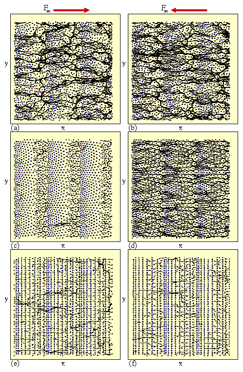
 Figure 3:
The vortex locations (red dots), pinning site locations (open
blue circles), and vortex trajectories (black lines)
for samples with B/Bϕ = 1.0, Fp = 1.5, and Fac = 1.5,
highlighting the enhanced effectiveness of the ratchet mechanism in
the Conf array.
(a) The trajectories for the positive half of the ac drive cycle in
the RandG array showing the formation of disordered flow channels.
(b) The negative half of the ac drive cycle in the RandG array has a
similar pattern and density of flow channels.
(c) In the positive half of the ac drive cycle for the Conf array,
the vortices cannot move past the densely pinned region.
(d) In the negative half of the ac drive cycle in the Conf array,
the vortices can easily funnel between the arches
in the conformal array.
(e) In the positive half of the ac drive cycle for the SquareG array,
vortices can slip through the interstitial regions between pinned
vortices.
(f) Similar interstitial motion occurs in the negative
half of the ac drive cycle for the SquareG array.
|
