Physical Review B 98, 134418 (2018)

Nonequilibrium Phases and Segregation for Skyrmions on Periodic Pinning Arrays

C. Reichhardt, D. Ray, and C. J. O. Reichhardt

Theoretical Division and Center for Nonlinear Studies, Los Alamos National Laboratory, Los Alamos, New Mexico 87545, USA

(Received 30 July 2018; published 11 October 2018)

Using particle-based simulations, we examine the collective dynamics of skyrmions interacting with periodic pinning arrays, focusing on the impact of the Magnus force on the sliding phases. As a function of increasing pinning strength, we find a series of distinct dynamical phases, including an interstitial flow phase, a moving disordered state, a moving crystal, and a segregated cluster state. The transitions between these states produce signatures in the skyrmion lattice structure, the skyrmion Hall angle, the velocity fluctuation distributions, and the velocity-force curves. The moving clustered state is similar to the segregated state recently observed in continuum-based simulations with strong quenched disorder. The segregation arises from the drive dependence of the skyrmion Hall angle, and appears in the strong pinning limit when the skyrmions have nonuniform velocities, causing different portions of the sample to have different effective skyrmion Hall angles. We map the evolution of the dynamic phases as a function of the system density, the ratio of the Magnus force to the dissipative term, and the ratio of the number of skyrmions to the number of pinning sites.
I. INTRODUCTION
II. SIMULATION
III. DYNAMIC PHASES AND CLUSTERING
A. Directional locking
B. Varied pinning strength
IV. CHANGING THE STRENGTH OF THE MAGNUS FORCE
V. VARIED FILLING FACTOR
VI. VARIED PINNING DENSITY
VII. SUMMARY
REFERENCES

I.  INTRODUCTION

Numerous systems can be modeled as a collection of interacting particles that are coupled to an underlying periodic substrate. The ratio of the number of particles to the number of substrate minima, known as the filling factor, can be an integer, a rational fraction, or an irrational fraction. As a function of filling factor, different types of crystalline, partially disordered, and disordered states can arise depending on the symmetry of the underlying substrate [1,2]. Commensuration effects arise for certain integer or rational filling factors that strongly affect the static and dynamic phases [3,4]. Examples of systems exhibiting commensuration behavior include atoms on ordered substrates [5], colloids interacting with two-dimensional periodic substrates [6,7,8,9,1], vortices in type-II superconductors with periodic pinning arrays [10,11,2,12,13,14], and vortices in Bose Einstein condensates with optical trap arrays [15,16]. Under an applied drive, a rich variety of distinct sliding phases appear [4]. The critical driving force Fc needed to induce depinning typically exhibits a maximum at commensurate fillings, while incommensurate fillings contain localized regions with a lower depinning threshold that produce a flow of soliton-like excitations at depinning, followed at increasing driving forces by additional dynamical phases as the other particles depin in a multi-step depinning process [4,9,1,2,17,18,19,20,21,22,23,24,25]. These systems also exhibit a variety of different types of sliding phases, including the soliton-like motion of interstitials or vacancies, grain boundary flow, chains of flowing particles moving around pinned particles, disordered or strongly fluctuating flow phases, and coherent moving crystal phases. Transitions between the sliding phases can be characterized by changes in the velocity-force curves, fluctuations, and structure of the particles [17].
Vortices in type-II superconductors pass through a particularly rich set of static and dynamic phases when interacting with a periodic substrate. Commensuration effects produce peaks in the critical current or the force needed to depin vortices at certain integer [9,2,12,13,14,26] and rational filling factors [27,28,29]. The pinning lattice consists of localized sites that can capture one or more vortices. Additional vortices that are not in the pinning sites sit in the interstitial regions between occupied pinning sites, and the combination of directly pinned vortices and indirectly pinned interstitial vortices produces the variety of dynamical phases found in simulations [18,27,30,31,32,33,34,35] and experiments [1,26,36,37].
Skyrmions in chiral magnets [38,39,40,41,42,43] have many similarities to superconducting vortices. The skyrmions are particle-like magnetic textures that form triangular lattices, can be driven with an applied current, and also exhibit depinning and sliding phases [40,44,45,46,47,48,49,50]. One of the key differences between skyrmions and superconducting vortices is that the skyrmion dynamics is strongly influenced by a Magnus force, produced by the skyrmion topology, which generates velocity components perpendicular to the forces experienced by the skyrmion [40,44,46,47]. Due to the Magnus force, the skyrmions move at an angle called the skyrmion Hall angle θsk with respect to the direction of the externally applied drive. As a skyrmion passes through a pinning site, its trajectory describes an arc which reduces the effective pinning threshold and also shifts the position of the skyrmion in a side jump effect. As a result, the skyrmion Hall angle varies with applied current. In the presence of pinning, θsk=0 at the depinning threshold, and as the skyrmion velocity increases with increasing current, θsk also increases until it saturates to the clean or intrinsic value θintsk at high drives. This behavior was first observed in particle-based simulations [51,52,53,54] and was subsequently verified in experiments [55,56,57]. Continuum-based simulations with pinning also show that the skyrmion Hall angle is drive dependent [58,59], which provides further evidence that particle-based simulations capture many of the essential features of the skyrmion dynamics.
With the recent advances in creating nanostructured materials that support skyrmions, it should be possible to create carefully controlled periodic structures or pinning arrays for skyrmions, and in this work we use particle-based simulations to investigate the dynamics of skyrmions in square pinning arrays. In addition to the skyrmion physics, we address the general question of how the collective dynamics of particle assemblies on periodic substrates change in the presence of a non-dissipative Magnus force, and what new dynamic phases arise that are absent in the overdamped limit. Previous work on individual skyrmions moving over two-dimensional periodic substrates showed that the Magnus force strongly affects the dynamics [52]. Specifically, the drive dependence of the skyrmion Hall angle produces quantized steps in θsk as a function of driving current when the skyrmion locks to different symmetry directions of the substrate [52].
In this work we study collectively interacting skyrmions on a periodic substrate, where new dynamics emerge that are not present for an isolated skyrmion. In the overdamped limit, we find interstitial flow, disordered flow, and moving crystal flow phases, in agreement with previous work on vortices in periodic pinning arrays [17,18,32,36,37]. Upon introducing a nonzero Magnus force, these same three phases persist in the form of an interstitial flow that can lock to various symmetry angles of the substrate, a disordered flow phase, and a moving crystal phase. When both the substrate strength and the Magnus force are sufficiently large, we observe a transition to a moving clustered or segregated state that is similar to the skyrmion cluster state found in continuum-based simulations with strong pinning [60]. In our case, the clustering instability arises from the strong velocity dependence of θsk that appears when the pinning is strong. The skyrmions form bands traveling at different relative velocities, and these bands move toward one another. We observe a similar clustering effect for strong randomly placed pinning which will be described elsewhere. When the pinning is weak, the clustering effect is lost and we observe an Aubry type transition [61,62] on the square pinning lattice, where the pinned skyrmion lattice transitions to a floating triangular skyrmion lattice with a much lower depinning threshold. As the filling factor changes, we find several commensurate-incommensurate transitions leading to the stabilization of different types of pinned skyrmion crystalline states that are identical to those that occur in the overdamped limit since the ground configurations are not affected by the Magnus force. We also show that it is possible to have different types of moving segregated states such as a diagonal stripe phase in which the stripes move at an angle with respect to the major symmetry axis of the pinning substrate.
The paper is organized as follows. In Section II, we describe our simulation. In Section III we illustrate the dynamic phases with emphasis on the phase separated states, and we construct a dynamical phase diagram as a function of drive and pinning strength. Directional locking effects occur due to the periodicity of the pinning. In Section IV we study the effect of changing the relative strength of the Magnus force on the dynamic phases. The effect of varying the filling factor appears in Section V. In Section VI we consider the effect of changing the pinning density while holding the filling factor constant. We summarize our results in Section VII.

II.  SIMULATION

We utilize a particle-based model for skyrmions based on a modified Thiele equation that takes into account skyrmion-skyrmion and skyrmion-pin interactions [47,51,52,53,54,64]. This model has previously been shown to capture several features of skyrmion dynamics including the orientation of skyrmion lattices, pinning phenomena, and the drive dependence of the skyrmion Hall angle when pinning is present. We consider a two-dimensional system of size L ×L with periodic boundary conditions in the x- and y-directions containing Nsk skyrmions and Np pinning sites. The filling factor is f = Nsk/Np. For most of this work we hold the number of pinning sites fixed and vary Nsk, which can be achieved experimentally by changing the applied magnetic field.
The skyrmion dynamics are governed by the following equation of motion [47]
αd vi + αm
^
z
 
×vi = Fssi + Fpi + FD .
(1)
The velocity of skyrmion i is vi = d ri/dt, while αd and αm are the damping and Magnus terms, respectively. The damping term can be written as αd=−4παD where α is the Gilbert damping coefficient and D=ξπ2/8γdw [65]. Here ξ is the skyrmion diameter, γdw=π√{A/Keff} is the domain wall width, A is the spin-wave exchange stiffness, and Keff is the effective perpendicular magnetic anisotropy. The skyrmion-skyrmion interaction force is repulsive and takes the form [47] Fiss = ∑Nskj=1K1(rij)rij, where K1 is the modified Bessel function, rij = |rirj| is the distance between skyrmions i and j, and rij=(rirj)/rij. The unit of force F0 is equal to the skyrmion-skyrmion repulsive force per length at a separation of l0=ξ√{nsk} [47,51] where the skyrmion density nsk=Nsk/L2. The driving force FD=FDx represents an applied current. The magnitude of the current that would produce a force of magnitude FD is given by J=(e/h)FD [51]. In the absence of pinning the skyrmions move at the intrinsic skyrmion Hall angle θintsk = tan−1md) with respect to the driving direction. The pinning sites are modeled as localized parabolic potentials with a fixed radius Rp and strength Fp, Fip = ∑k=1Np(Fprikp/Rp)Θ(Rprikp)rikp where rikp=|rirkp|, rikp=(rirkp)/rikp, and Θ is the Heaviside step function. This same pinning model was previously used to study the statics and dynamics of superconducting vortices in periodic pinning arrays [18,27,30,32,33,34].
The initial skyrmion positions are obtained by simulated annealing, in which we start from a high temperature liquid state and gradually cool to T=0. After annealing we gradually increase the driving force in increments of δFD = 0.002, waiting 20000 simulation time steps between increments to ensure that the system has reached a steady state. For small values of Fp we have tested increments as small as δFD=1 ×10⁻⁶ to verify that the results are not affected by the choice of δFD. We measure 〈V||〉 = Nsk−1Nski=1 v||i and 〈V〉 = Nsk−1Nski=1 vi in the directions parallel and perpendicular to the drive, respectively, where vi||=vi ·x and vi=vi ·y, and we use these quantities to obtain the velocity ratio R=〈V〉/〈V||〉 and the measured skyrmion Hall angle θsk = tan−1(R). We also measure a quantity related to the standard deviation of the skyrmion velocities in the parallel and perpendicular directions, δV|| = √{ [∑iNsk (v||i)2 − 〈V||2]/Nsk} and δV = √{ [∑iNsk (vi)2 −〈V2]/Nsk}. To quantify the amount of ordering in the skyrmion lattice, we use the fraction of sixfold-coordinated skyrmions, P6=Nsk−1iNskδ(6−zi), where zi is the coordination number of skyrmion i obtained from a Voronoi tessellation. For a perfect triangular lattice, P6=1. We fix L = 36, Rp = 0.35, and Np = 256 while varying Fp, αmd, and Nsk, except in Section VI where we consider varied pinning density np=Np/L2. A summary of the dynamic phases we observe appears in Table  I.
Name Label Characteristic features
No skyrmions moving:
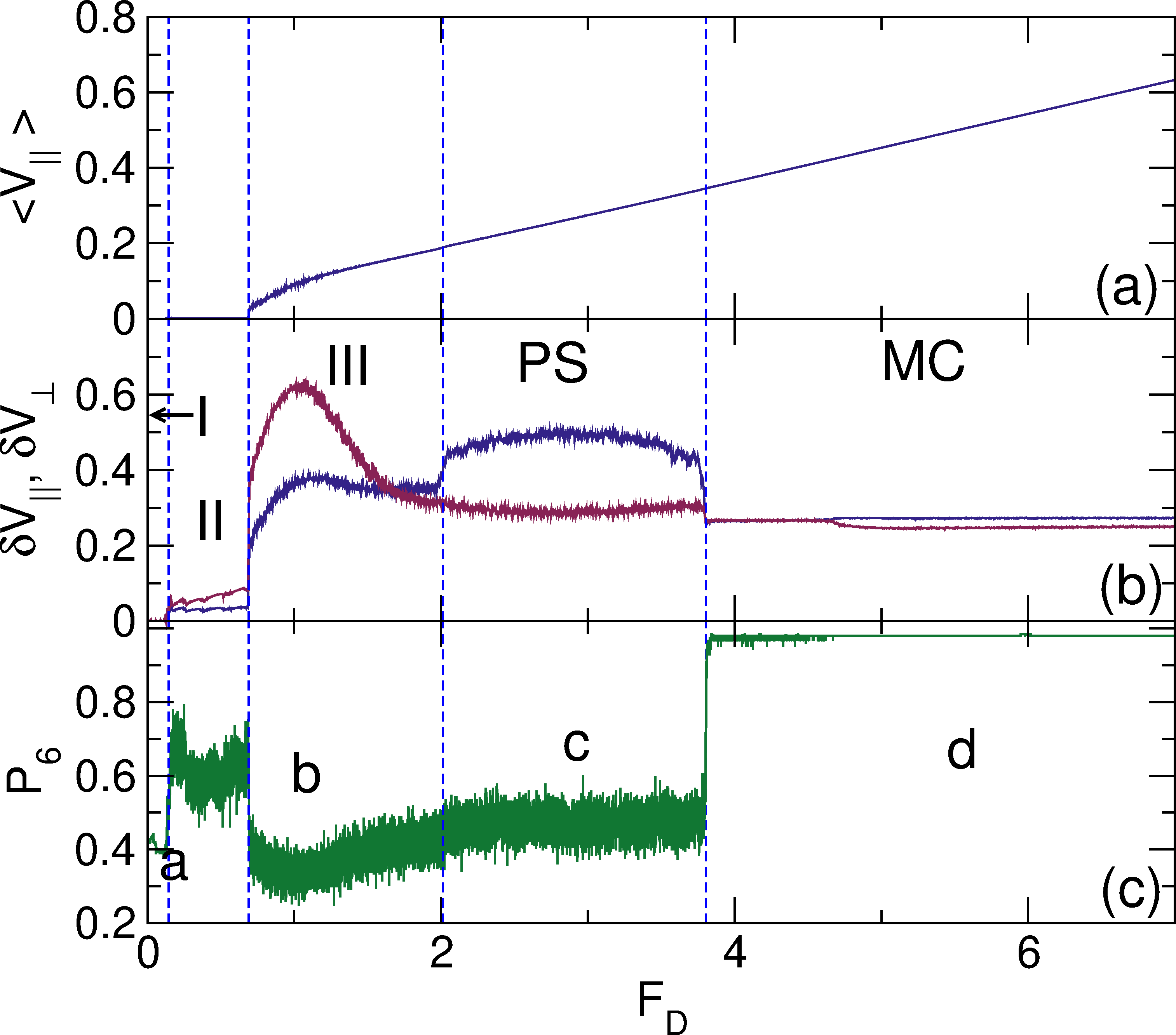
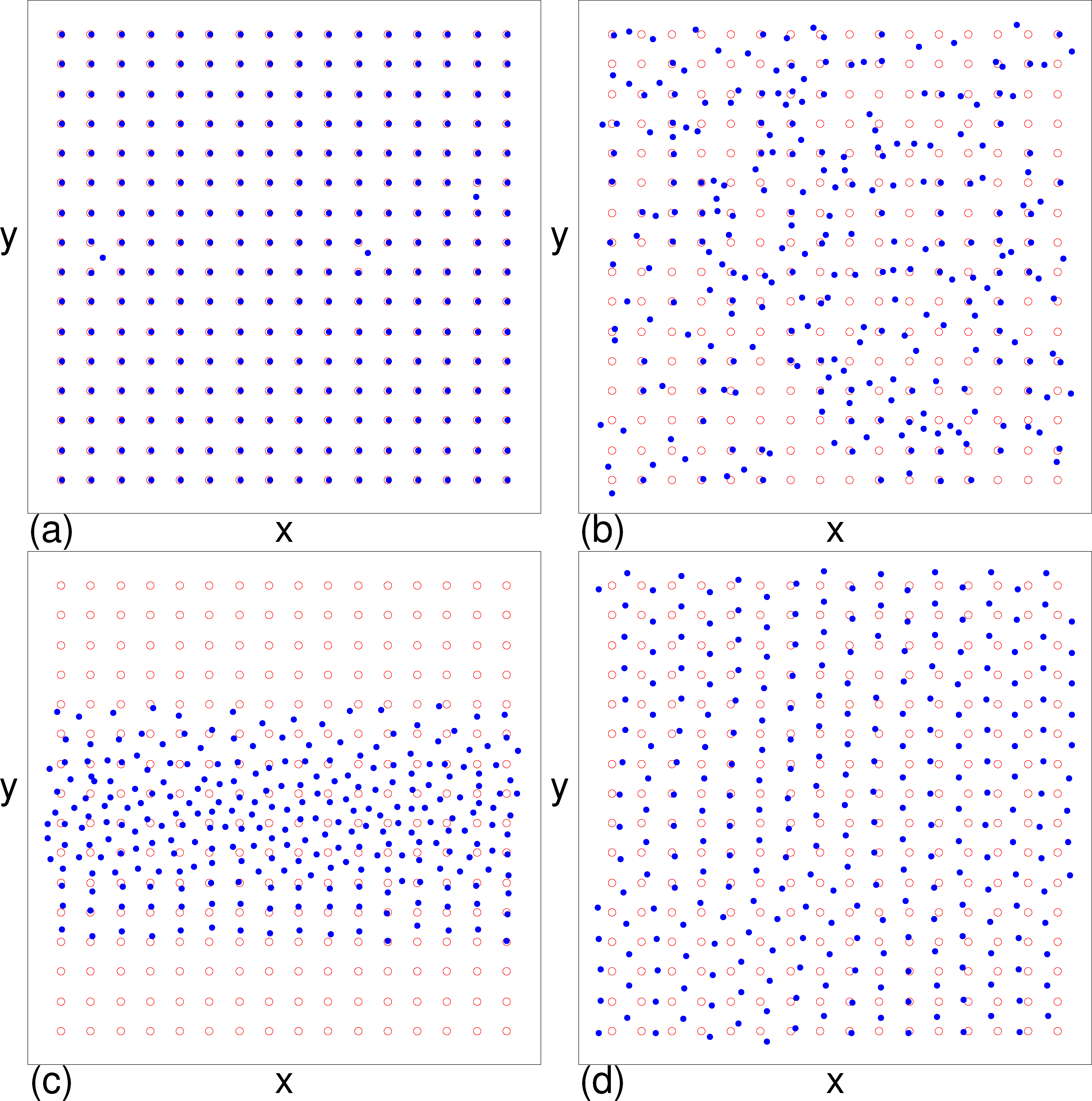
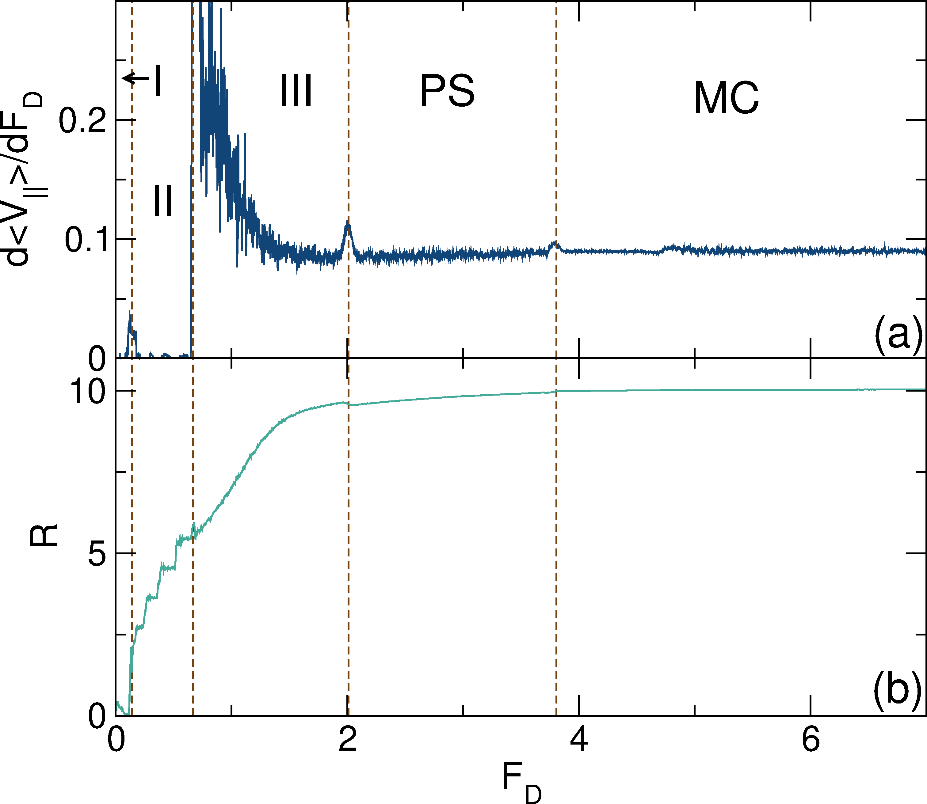
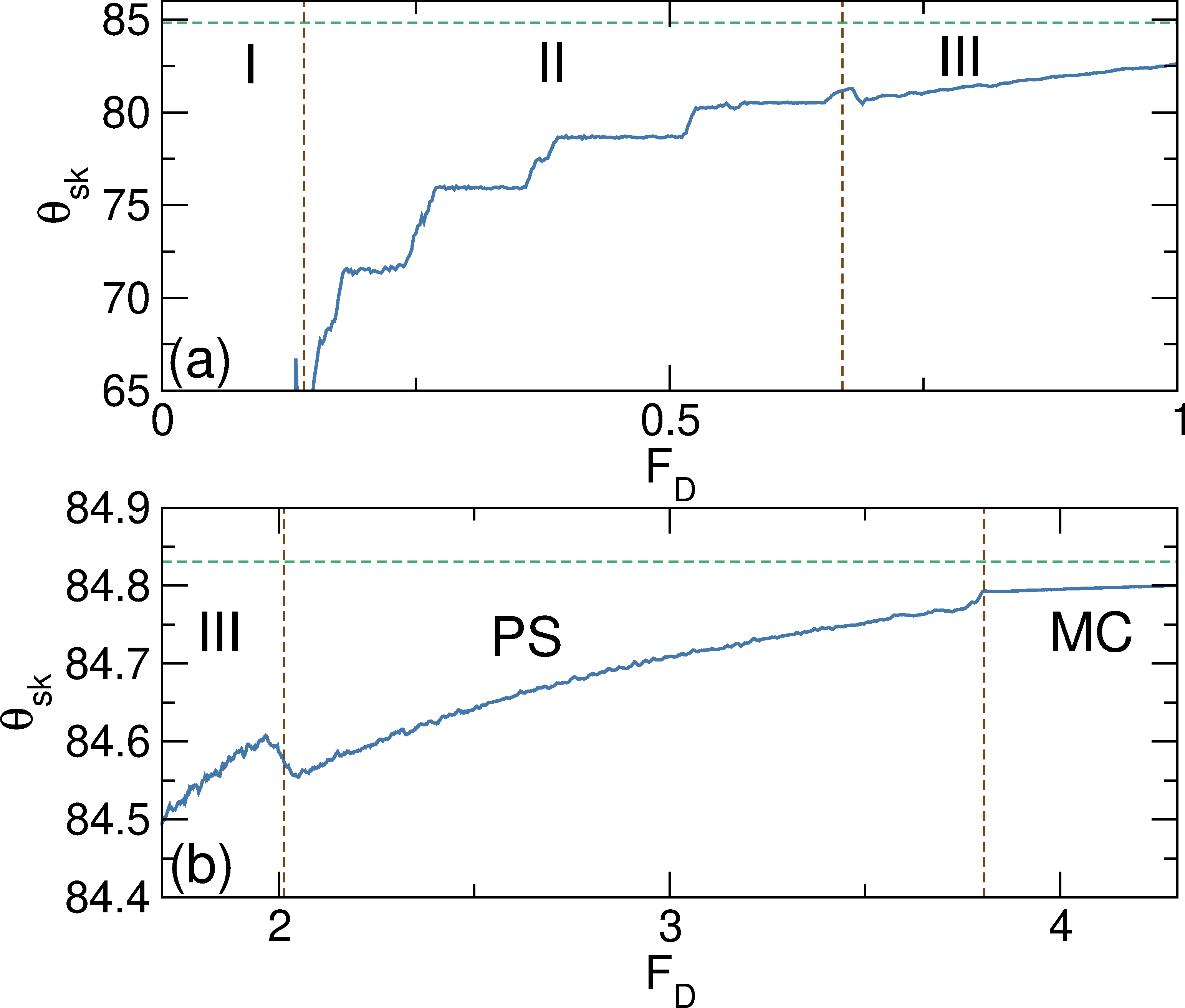
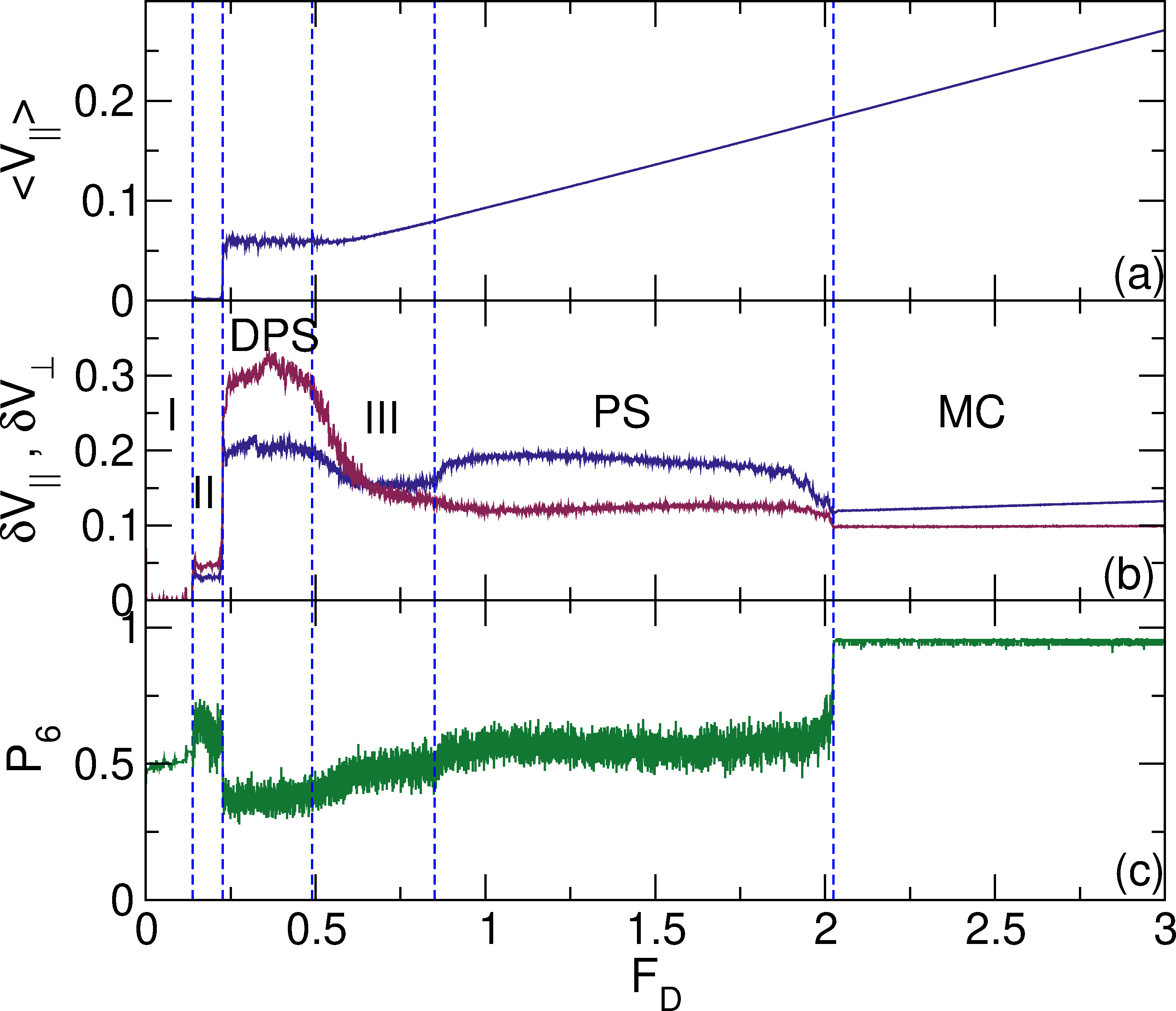
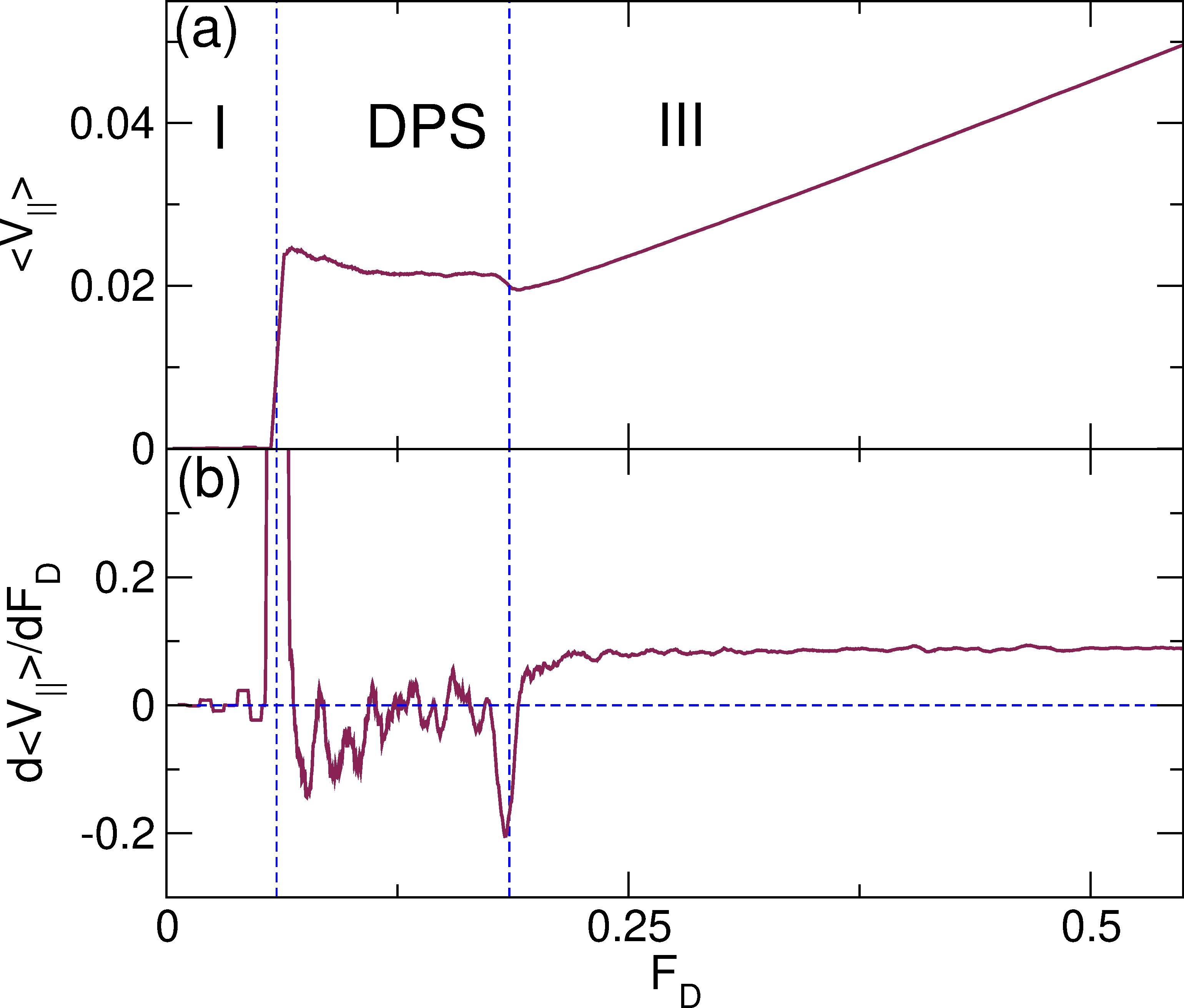
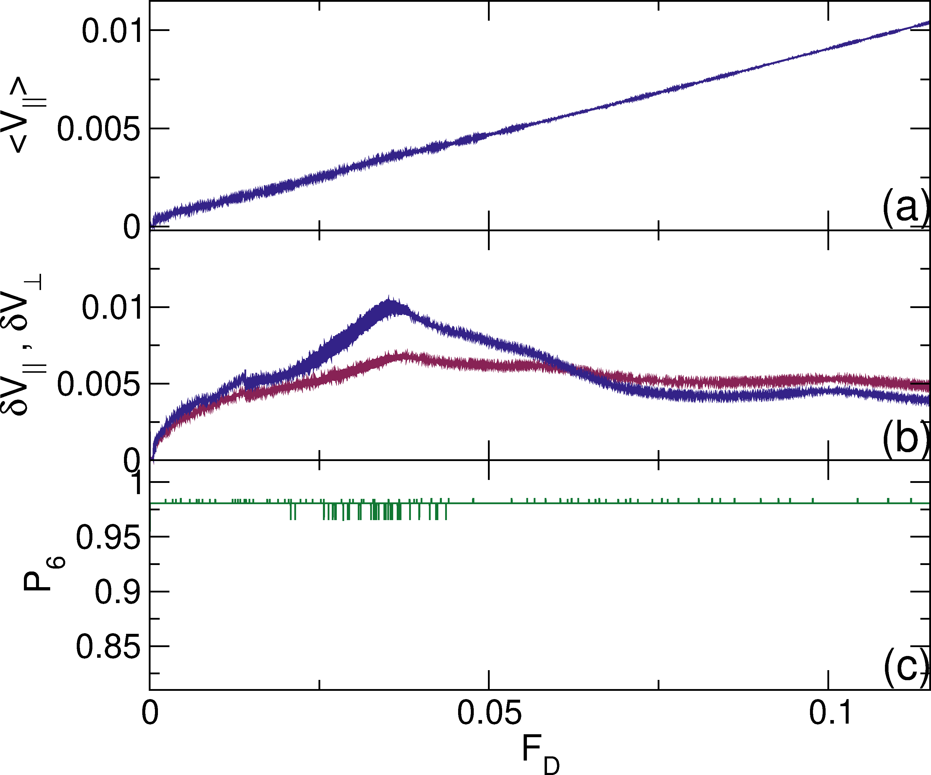
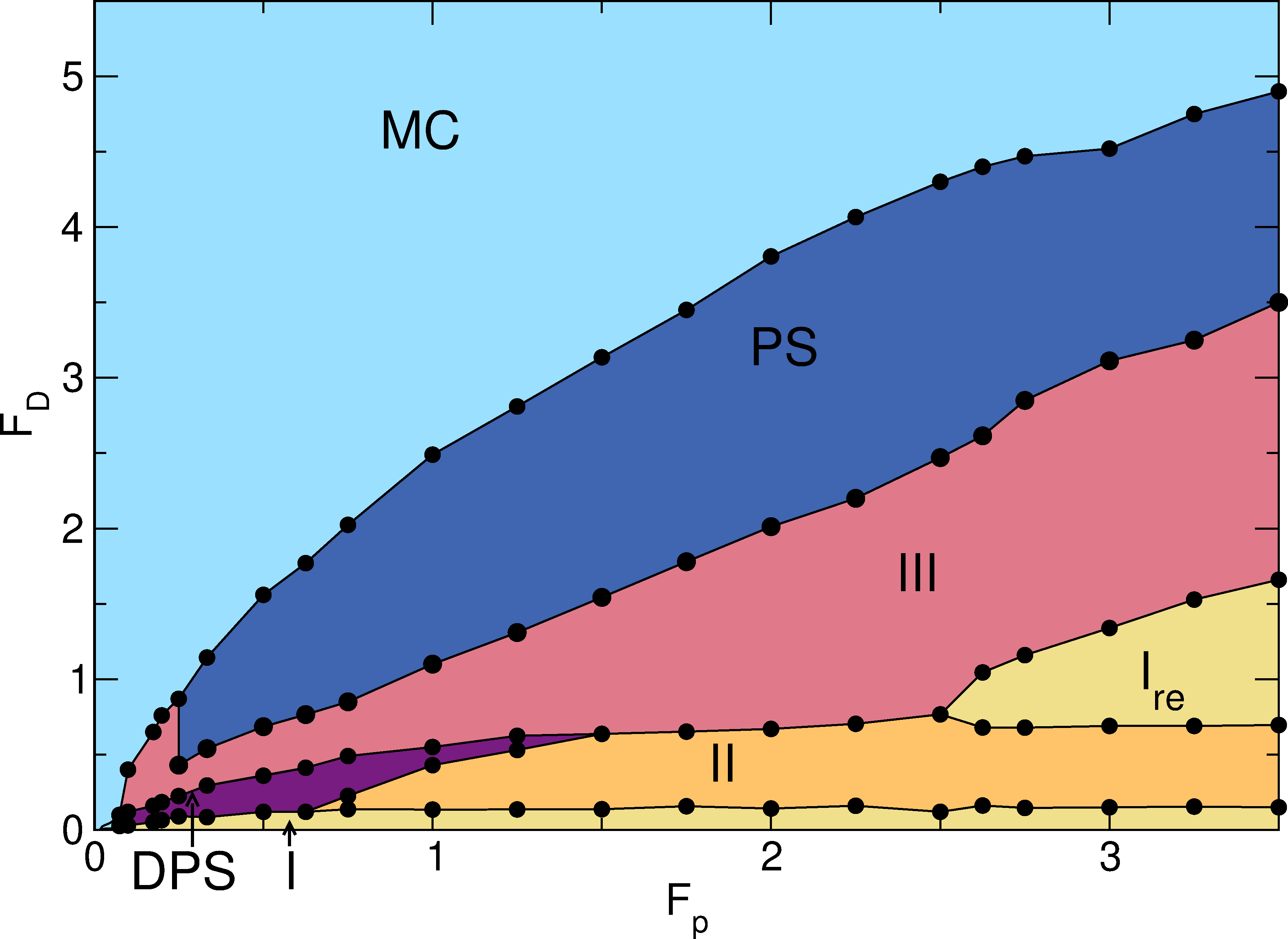
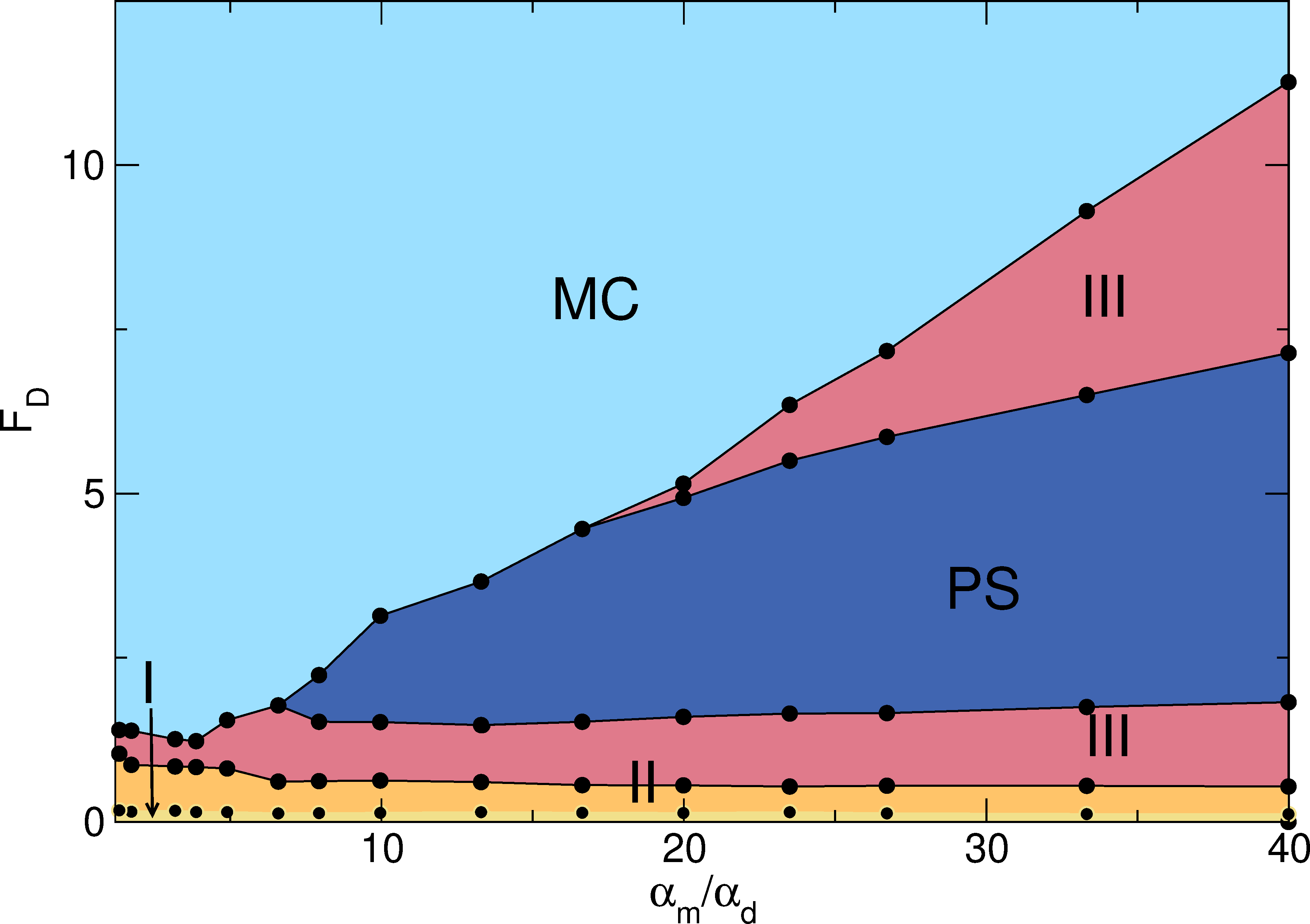
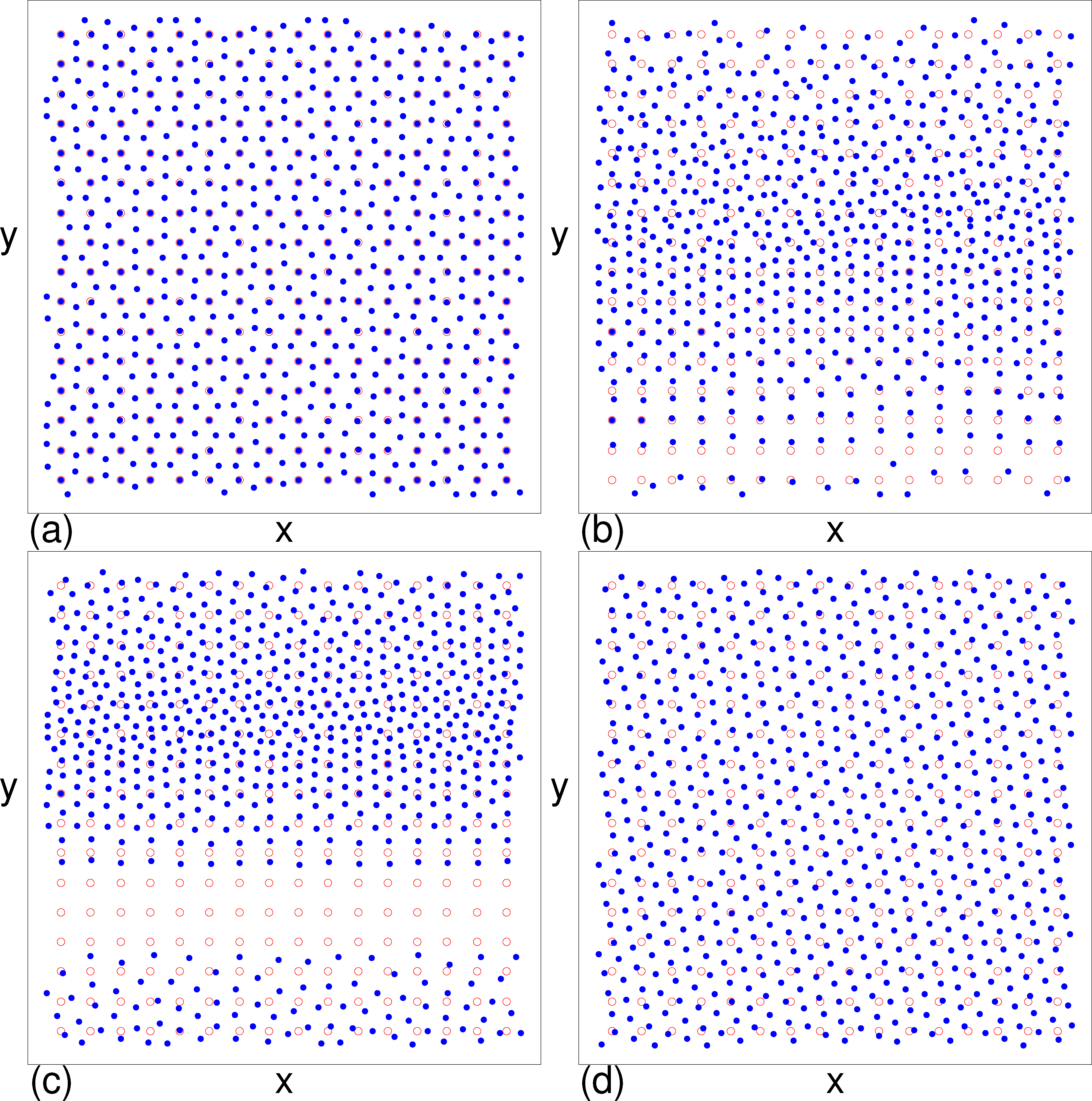
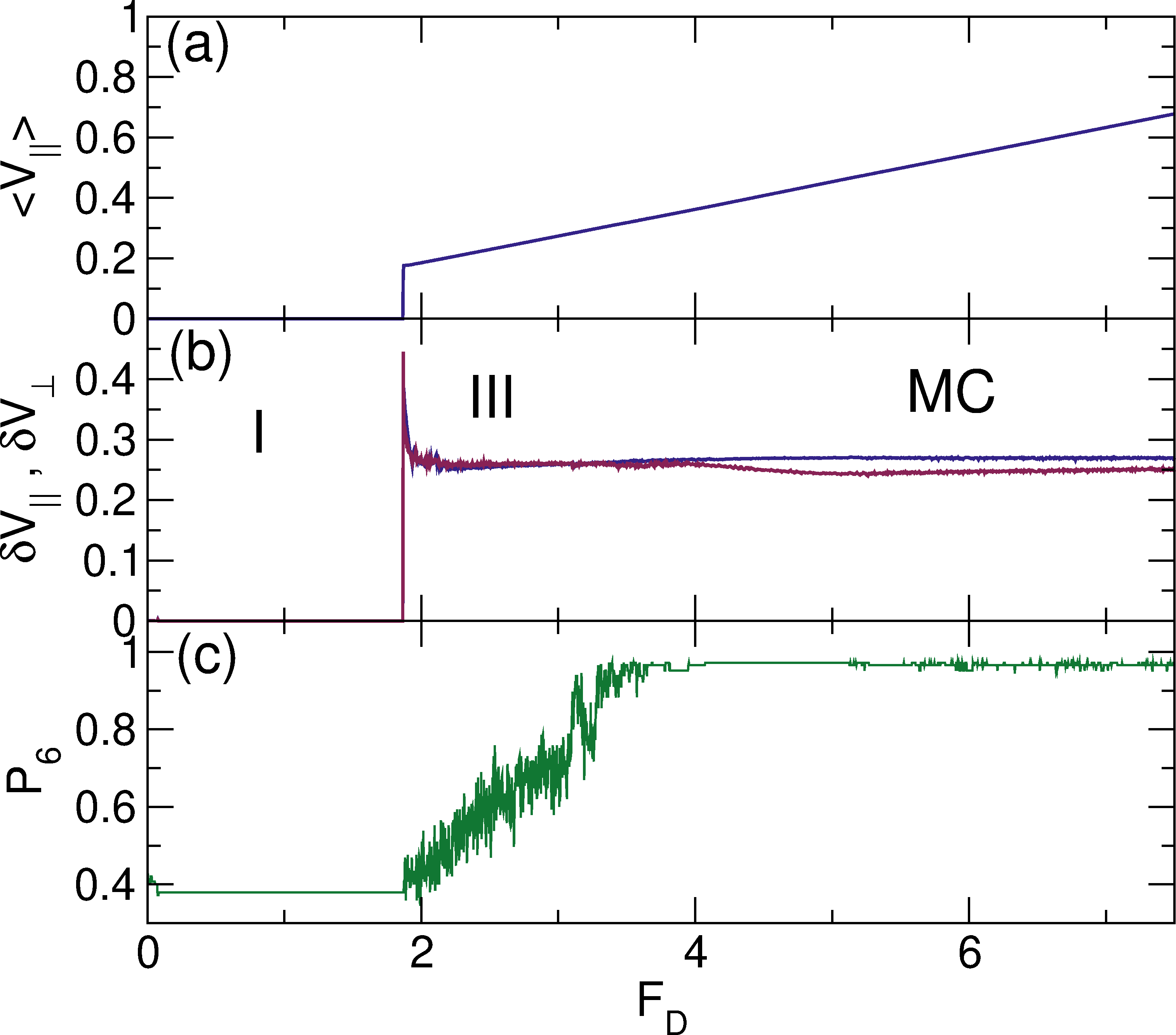
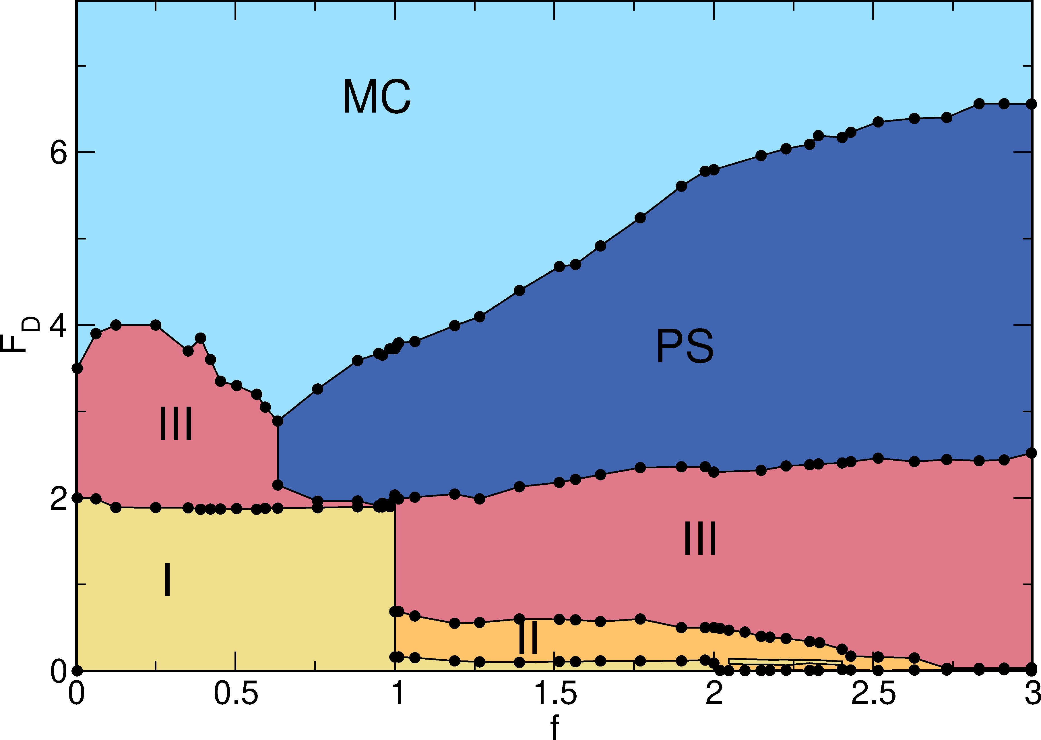
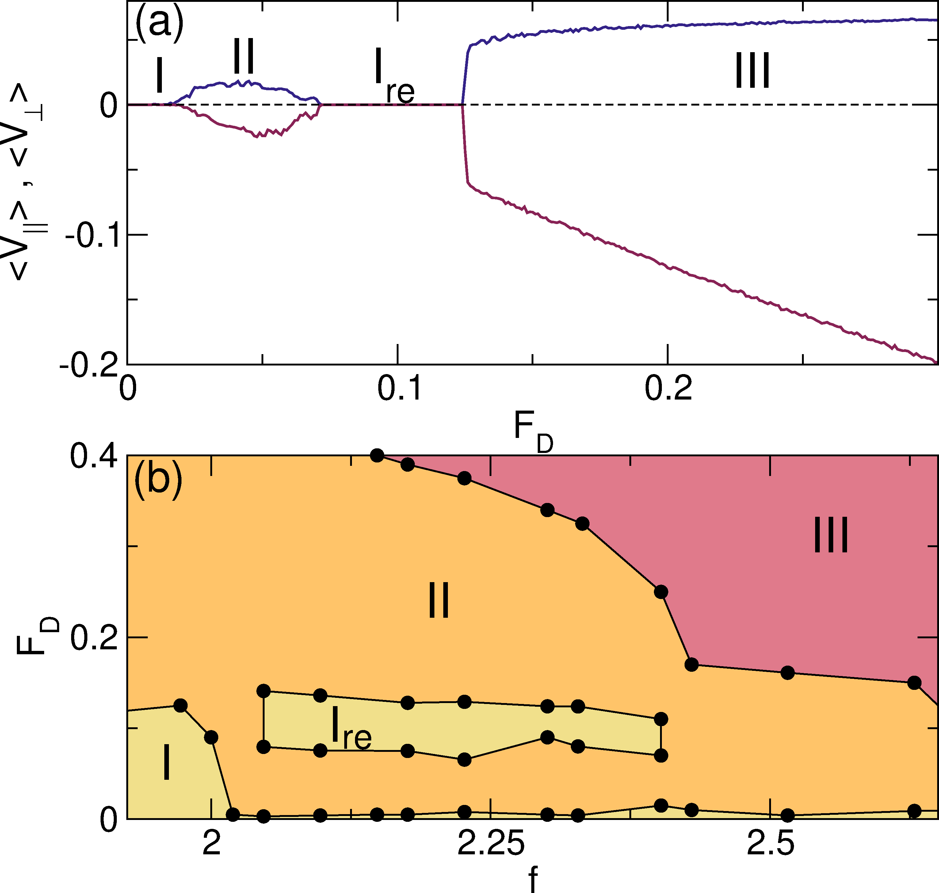
Pinned I Pinned square lattice containing interstitials
Reentrant Pinned Ire Reentrantly pinned square lattice containing interstitials
Pinned Commensurate PC Same as Phase I (Pinned)
Incommensurate Floating Solid IC Pinned triangular lattice floating over the substrate
Moving and pinned skyrmions coexist:
Interstitial Flow II Motion of only interstitial skyrmions between pinning rows
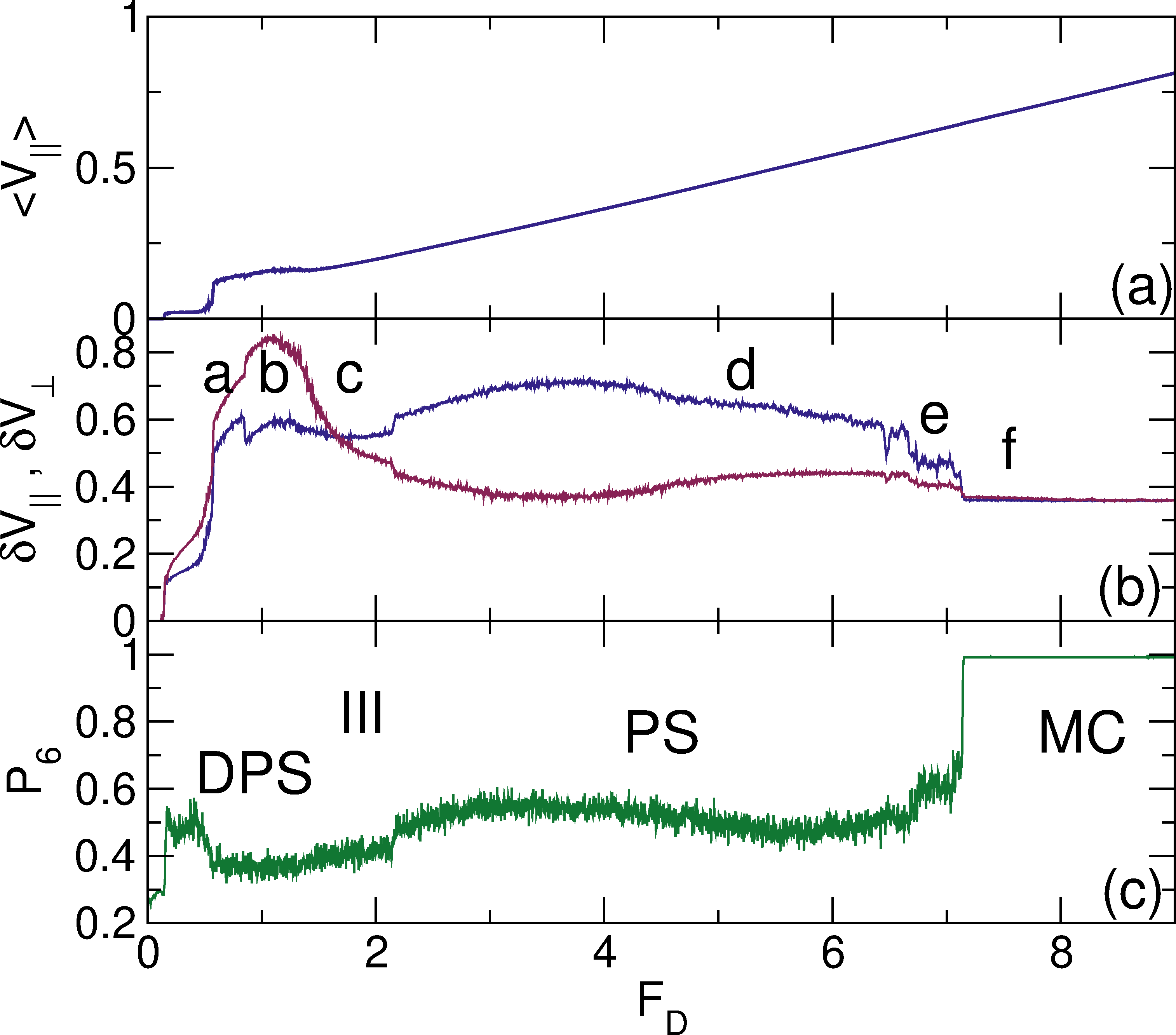
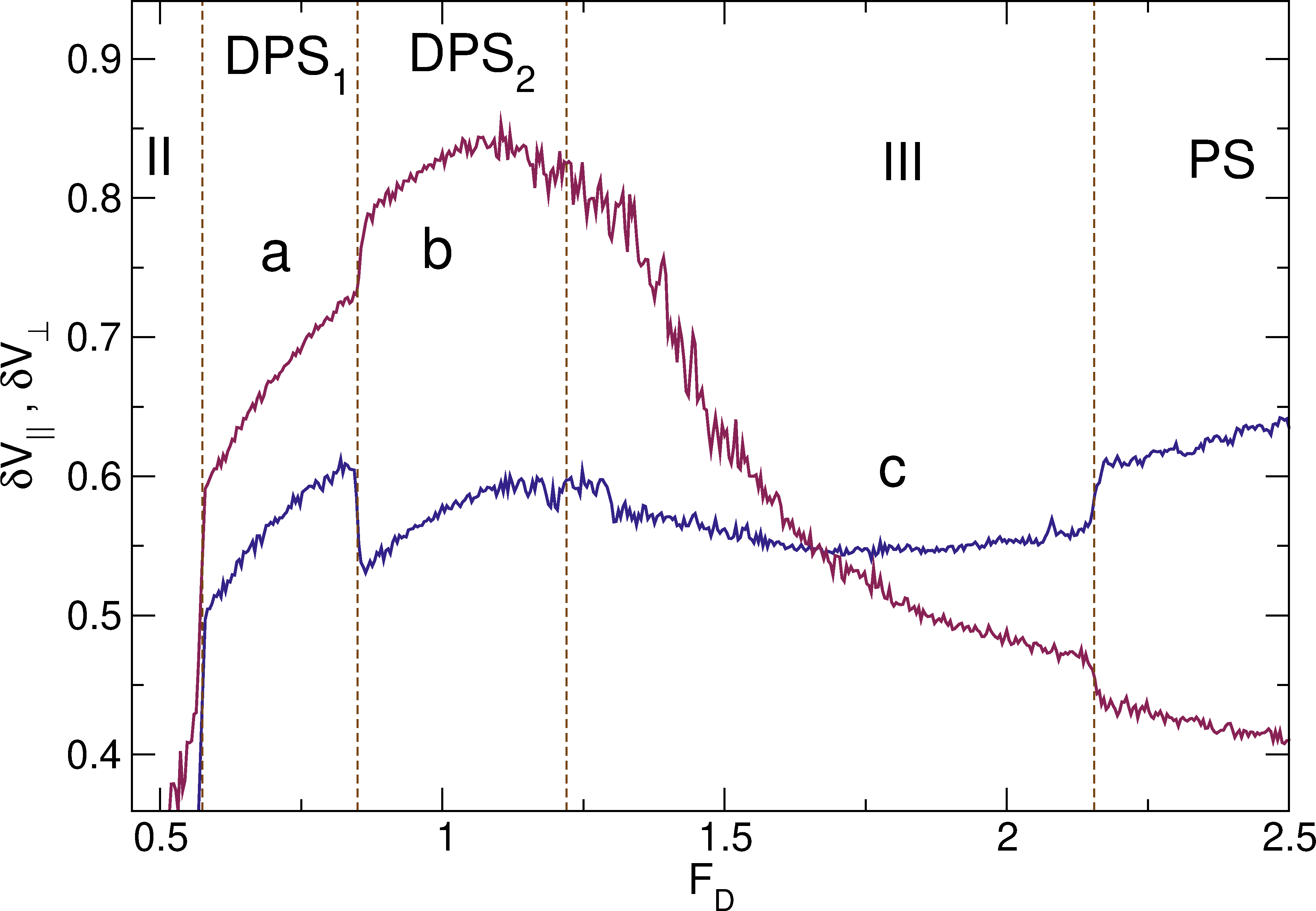
Disordered Flow III Individual skyrmions repeatedly pin and depin
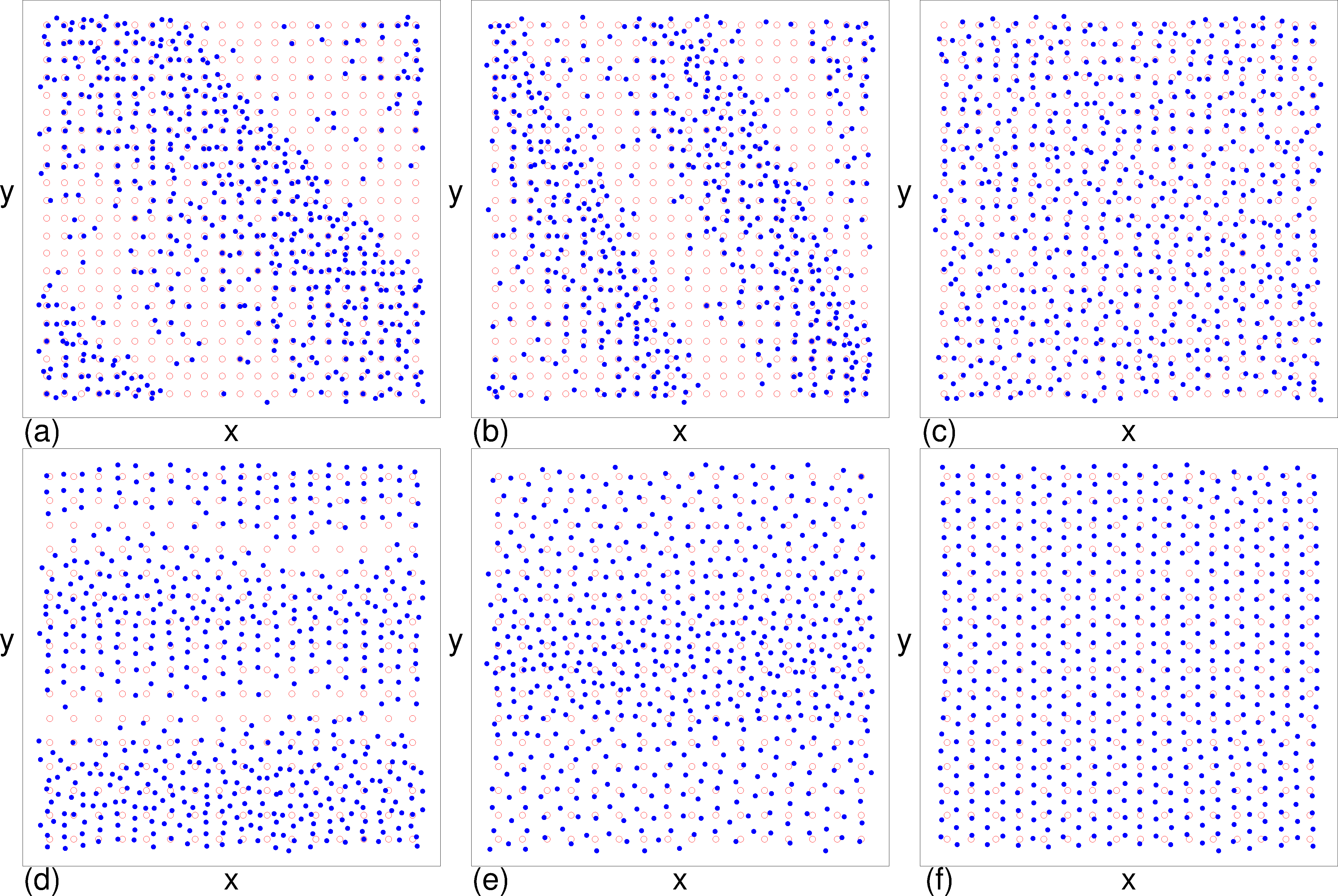
Diagonal Phase Separated DPS Moving skyrmions clump into dense stripes at angle to drive
Diagonal Phase Separated subphase 1 DPS1 Moving skyrmion stripes aligned  ∼ 45° from drive
Diagonal Phase Separated subphase 2 DPS2 Moving skyrmion stripes aligned  ∼ 67° from drive
All skyrmions moving:
Phase Separated PS Skyrmions clump into dense stripes aligned with drive
Moving Crystal MC Moving triangular crystal containing grain boundaries
Table 1: List of dynamic phases and their characteristic features.

III.  DYNAMIC PHASES AND CLUSTERING

Fig1.png
Figure 1: (a) 〈V||〉 vs FD for skyrmions moving in a square periodic pinning array with a filling factor of f=Nsk/Np=1.0117, pinning strength Fp=2.0 and pinning density np=0.1975 at αmd = 9.96. (b) The corresponding velocity deviations δV|| (blue) and δV (red) vs FD. (c) The corresponding fraction of six-fold coordinated skyrmions P6 vs FD. Dashed lines indicate the boundaries between the pinned state (phase I), the flow of interstitial skyrmions (phase II), the disordered flow state (phase III), the segregated or phase-separated state (phase PS), and the moving crystal (phase MC). The letters a to d in panel (c) indicate the values of FD at which the skyrmion images in Fig. 2 were obtained.
Fig2.png
Figure 2: Skyrmion (blue dots) and pinning site (red circles) locations at one instant in time for the system in Fig. 1 with f=1.0117, Fp=2.0, np=0.1975, and αmd=9.96. (a) The pinned phase I at FD = 0. (b) The disordered flow phase III at FD = 1.0. (c) The segregated or phase separated phase PS at FD = 3.0. (d) The moving crystal phase MC at FD = 5.5.
In Fig. 1(a) we plot the velocity-force curve 〈V||〉 versus FD for a system with f=1.0117, a pinning density of np = 0.1975, Fp = 2.0, and αmd = 9.96. The 〈V〉 versus FD curve (not shown) has the same shape but is larger in magnitude. Figure 1(b) shows the mean square deviations in the instantaneous velocities for both the parallel (δV||) and perpendicular (δV) directions versus FD, while Fig. 1(c) shows the corresponding fraction of six-fold coordinated skyrmions P6 vs FD. The vertical dashed lines highlight the five different dynamic phases that arise. Phase I is a pinned state with 〈V||〉 = 〈V〉 = 0. As illustrated in Fig. 2(a) at FD = 0, the skyrmions form a commensurate square lattice with a small number of additional skyrmions in the interstitial regions between pinning sites. Phase II consists of interstitial flow, in which only the interstitial skyrmions depin and move around the commensurate skyrmions, which remain pinned. The flow in phase II exhibits a series of directional locking effects which we explore in detail in Section III A. The value of 〈V||〉 is small but finite, and there are jumps in δV||, δV, and P6 at both ends of the interval 0.15 < FD < 0.7 where phase II occurs, as shown in Fig. 1. Within phase II the overall lattice structure is similar to that of phase I since most of the skyrmions remain pinned. Upward jumps in 〈V||〉, δV||, and δV mark the onset of the disordered flow phase III, which appears in the interval 0.7 ≤ FD ≤ 2.01, and consists of a combination of pinned and flowing skyrmions as illustrated in Fig. 2(b) at FD = 1.0.
Near FD = 2.0 there is a transition to the clustered or segregated state, shown in Fig. 2(c) at FD = 3.0, where the skyrmions clump into a dense stripe. We call this the segregated or phase separated phase PS. There is an upward jump in δV|| at the III-PS transition, and δV|| remains larger than δV throughout the PS phase due to the alignment of the stripe with the driving direction. This phase separated state is very similar to that observed in continuum-based simulations of skyrmions moving over random pinning [60], and we find that the phase separation occurs only when the pinning is sufficiently strong, in agreement with the continuum-based results. The creation of the segregated state in the continuum models was attributed to the emission of spin waves that produce an effective attraction between the skyrmions [60]. In our system, no spin waves are present, and the segregation occurs due to the velocity dependence of the skyrmion Hall angle in the presence of pinning. If different regions of the system are moving at different relative velocities, each region will have a different skyrmion Hall angle, causing the skyrmions in adjacent regions to gradually move toward one another. In Fig. 2(c), the bottom three rows of the stripe form a square lattice structure that is partially commensurate with the pinning sites, so that in this region of the stripe, the local filling factor is close to floc=1. The net skyrmion velocity is reduced close to commensuration, so the value of θsk is smaller in this region. The upper region of the stripe is denser with floc > 1, and this incommensurate state has a higher net skyrmion velocity and a correspondingly larger value of θsk. As a result, there are velocity and θsk differentials across the sample, causing the larger θsk skyrmions to collide with the smaller θsk skyrmions. The skyrmions develop a nonuniform density profile that permits the commensurate and incommensurate regions to slide past each other in the driving direction, preserving a nonuniform velocity profile and producing an increased velocity variation δV|| in the PS phase, as shown in Fig. 1(b). At larger values of FD, θsk begins to saturate as shown in previous simulations [51,52,53,54,58,59] and experiments [55], destroying the spatial differential in θsk and allowing the skyrmions to form a moving crystal state (MC), as illustrated in Fig. 2(d) at FD = 5.5. The PS-MC transition is accompanied by drops in δV|| and δV, which become nearly isotropic, along with an upward jump in P6 to a value just below P6=1.0. The drops in δV|| and δV in the MC phase occur since the skyrmions are all moving at the same velocity.

A.  Directional locking

Fig3.png
Figure 3: (a) dV||〉/dFD vs FD for the system in Fig. 1 with f=1.0117, Fp=2.0, np=0.1975, and αmd=9.96 showing peaks at the transitions between different phases. I: pinned; II: interstitial flow; III: disordered flow; PS: phase separated; MC: moving crystal. (b) R = 〈V〉/〈V||〉 vs FD for the same system.
In Fig. 3(a,b) we plot the differential mobility dV||〉/dFD and the velocity ratio R=〈V〉/〈V||〉 versus FD for the system in Fig. 1. Pronounced peaks appear in dV||〉/dFD across the I-II and II-III transitions, along with smaller peaks at the III-PS and PS-MC transitions. The velocity ratio is zero in phase I, and increases in phases II and III until it is close to the intrinsic value Rintmd near the onset of the PS state. Within phase II, a series of steps appear in R when the interstitial skyrmion flow passes through a sequence of directionally locked states as FD increases, similar to the previously studied directional locking of skyrmion motion on square arrays in the single skyrmion limit [52]. These locking effects occur due to the velocity dependence of the skyrmion Hall angle in the presence of pinning, which causes the direction of skyrmion motion to rotate with increasing FD. Due to the underlying symmetry of the pinning potential the rotation is not continuous; instead, the motion becomes locked at integer values of R [52]. The steps in Fig. 3(b) appear at R = 2, 3, 4, 5 and 6, but all higher locking plateaus are cut off when the system enters phase III. Within phase III, R increases smoothly, and small dips in R appear at the III-PS and PS-MC transitions together with small peaks in the differential mobility in Fig. 3(a).
Fig4.png
Figure 4: θsk vs FD for the system in Fig. 3 with f=1.0117, Fp=2.0, np=0.1975, and αmd=9.96, highlighting the directional locking steps in phase II (interstitial flow). (b) θsk vs FD for the same system in phases III (disordered flow), PS (phase separated), and MC (moving crystal), showing a jump down in θsk across the III-PS transition and a jump up across the PS-MC transition. The horizontal dashed lines in both panels indicate the disorder-free skyrmion Hall angle θskint.
In Fig. 4(a) we plot θsk = tan−1(R) versus FD, showing more clearly that θsk is quantized in phase II. The integer ratio R = 3 corresponds to the step at θsk = 71.56°, and there are also steps for the R=4, R=5, and R=6 ratios, with the latter corresponding to the step at θsk = 80.53°. Much smaller steps appear at some rational fractional values of R similar to what was observed in the single skyrmion limit [52]. In Fig. 4(b) we show θsk versus FD across the III-PS and PS-MC transitions. There is a drop in θsk at the III-PS transition caused when the more slowly moving commensurate skyrmions block the flow of the faster moving incommensurate skyrmions, reducing the net velocity in the perpendicular direction and thereby reducing both R and θsk. When the PS structure destabilizes at the PS-MC transition, the skyrmions begin to move at a uniform velocity in the MC phase, eliminating the blocking of the flow of faster skyrmions by slower skyrmions, and causing θsk to increase.
Fig5.png
Figure 5: The structure factor S(k) for the system in Fig. 1 with f=1.0117, Fp=2.0, np=0.1975, and αmd=9.96. (a) Pinned phase I. S(k) for the interstitial flow phase II (not shown) is similar in appearance. (b) Disordered flow phase III. (c) The PS phase. (d) The MC phase.
Some experimental techniques cannot directly access the real-space position of the skyrmions but instead measure the structure factor S(k) = Nsk−1|∑Nskiexp(−ik·ri)|2. Figure 5(a) shows that S(k) in phase I for the system in Fig. 1(a) has square symmetry since the skyrmions are predominantly localized in the square pinning array. In the interstitial flow phase II, S(k) also has strong square ordering since most of the skyrmions remain pinned. In the disordered flow phase III, where a combination of pinned and flowing skyrmions appear, S(k) exhibits a smearing due to the positional disorder, as shown in Fig. 5(b); however, there is still significant weight at the square lattice wavevectors due to the pinned skyrmions. In the PS phase illustrated in Fig. 5(c), S(k) contains a series of peaks along the ky axis, indicative of smectic or stripe like ordering. An additional ring-like structure appears at larger values of k due to the partial disordering of the skyrmions within the stripe. In the MC phase, S(k) reveals strong triangular ordering, as highlighted in Fig. 5(d). These results show that the different phases have distinct signatures in both real and reciprocal space, and that transitions between the phases are associated with changes in θsk and the transport properties.

B.  Varied pinning strength

Fig6.png
Figure 6: (a) 〈V||〉 vs FD for a system with f=1.0117, np=0.1975, αmd=9.96, and larger Fp=3.0. (b) The corresponding δV|| (blue) and δV (red) vs FD. (c) The corresponding P6 vs FD. Dashed lines indicate the boundaries between the phases. I: pinned, II: interstitial flow; Ire: reentrant pinned; III: disordered flow; PS: phase separated; MC: moving crystal.
We next consider the evolution of the phases for the system in Fig. 1 for varied pinning strength Fp. In Fig. 6 we plot 〈V||〉, δV||, δV, and P6 versus FD for samples with f=1.0117, np=0.1975, and αmd=9.96 at a larger Fp = 3.0. The III-PS and PS-MC transitions both shift to higher values of FD compared to the Fp=2.0 case. Although the overall behavior is similar for both values of Fp, in Fig. 6 we find a reentrant pinned phase falling between phases II and III over the range 0.7 < FD < 1.35. In the FD=0 pinned phase I, the interstitial skyrmions are pinned by the interactions with skyrmions located at the pinning sites. The interstitial skyrmions depin and experience a series of directional locking transitions in phase II, but the stronger pinning sites are able to capture and repin the interstitial skyrmions when the changing direction of motion causes the skyrmions to pass directly over the pinning sites, producing the reentrant pinned phase Ire. For lower Fp, each pinning site can capture only one skyrmion, so the reentrant pinning does not occur; however, for Fp > 2.5, a sufficiently large value of FD can shift an already pinned skyrmion far enough to the edge of the pinning site to permit a second skyrmion to enter the other side of the pinning site and become trapped in phase Ire. At FD > 1.3 for the Fp=3.0 system, the drive is strong enough to depin the doubly occupied pinning sites, and the system transitions to disordered phase III flow. In general, we find that the same phases persist as Fp is further increased, with the width of the Ire region increasing. When Fp becomes sufficiently large, the interstitial skyrmions become trapped in doubly-occupied pinning sites all the way down to FD=0, causing phase II to disappear. We also find that the jump in P6 at the PS-MC transition becomes less sharp for stronger Fp.
Fig7.png
Figure 7: (a) 〈V||〉 vs FD for a system with f=1.0117, np=0.1975, and αmd=9.96 at Fp=0.75 where a diagonal phase separated state, phase DPS, appears as illustrated in Fig. 8(a). (b) The corresponding δV|| (blue) and δV (red) vs FD. (c) The corresponding P6 vs FD. Dashed lines indicate the phase boundaries. I: pinned; II: interstitial flow; DPS: diagonal phase separated; III: disordered flow; PS: phase separated; MC: moving crystal.
Fig8.png
Figure 8: (a,b) Skyrmion (blue dots) and pinning site (red circles) locations at one instant in time for the system in Fig. 7 with f=1.0117, np=0.1975, αmd=9.96, and Fp=0.75. (a) The diagonal phase separated state DPS at FD = 0.25, where multiple diagonal phase separated bands appear. (b) The phase separated PS state at FD = 1.5, where the skyrmion density is more uniform. The pinning sites are not shown for clarity. (c,d) Skyrmion and pinning site locations for a system with f=1.0117, np=0.1975, αmd=9.96, and Fp=0.2. (c) The DPS phase at FD = 0.075, where only one band of skyrmions forms. (d) Phase III flow at FD = 0.55. The pinning sites are not shown for clarity.
In Fig. 7 we plot 〈V||〉, δV||, δV, and P6 versus FD for the same system in Fig. 6 but at a weaker Fp = 0.75. We again observe phases I, II, III, PS, and MC; however, a diagonal phase separated state called phase DPS now appears between phases II and III. In the DPS phase, 〈V||〉 gradually decreases with increasing FD as shown in Fig. 7(a). We illustrate the DPS flow at FD=0.25 in Fig. 8(a), where the skyrmions form a series of dense bands at an angle to the driving direction. One distinction between the DPS and PS phases is that in the DPS phase there is a combination of pinned skyrmions and moving skyrmions, whereas in the PS phase, all the skyrmions are moving. At higher driving the system undergoes uniform disordered phase III flow before transitioning into the PS phase shown in Fig. 8(b) for FD = 1.5. In general, as Fp decreases, the width of the stripe in the PS phase increases. Near FD = 2.0, the system transitions into the MC phase.
Fig9.png
Figure 9: (a) 〈V||〉 vs FD for a system with f=1.0117, np=0.1975, and αmd=9.96 at Fp = 0.2. Here phase II is lost and the system depins directly from phase I to phase DPS. (b) The corresponding δV|| (blue) and δV (red) vs FD. (c) The corresponding P6 vs FD. Dashed lines indicate the phase boundaries. I: pinned; DPS: diagonal phase separated; III: disordered flow; MC: moving crystal.
Fig10.png
Figure 10: (a) A blowup of 〈V||〉 vs FD for the system in Fig. 9 with f=1.0117, np=0.1975, αmd=9.96, and Fp=0.2 in the region containing the I-DPS and DPS-III transitions. A dip in 〈V||〉 appears at the DPS-III transition, producing negative differential conductivity, dV||〉/dFD < 0. (b) dV||〉/dFD vs FD for the same system. For clarity, this data has been subjected to a running average in order to reduce the noise.
In Fig. 9 we plot 〈V||〉, δV||, δV, and P6 versus FD for the system in Fig. 6 at Fp = 0.2, where phase II is lost and the system transitions directly from phase I to phase DPS. At lower values of Fp such as this, the repulsion between the interstitial skyrmions and the skyrmions at the pinning sites is strong enough that when the interstitial skyrmions depin, their motion causes the skyrmions in the neighboring pinning sites to depin as well, destroying the interstitial flow phase II. The PS phase is also lost and phase III is followed immediately by the MC phase. As Fp decreases, the spatial width of the bands in the DPS phase increases, as illustrated in Fig. 8(c) for the system in Fig. 9 at FD = 0.075. The disordered flow phase III in the same system is much more uniform than the phase III flow found at higher values of Fp, as shown in Fig. 8(d) at FD=0.55. The DPS-III transition is relatively sharp and appears as a jump down in δV|| and δV along with a jump up in P6. There is also a dip in 〈V||〉 indicating a drop in the average velocity of the skyrmions in the direction of drive at the DPS-III transition, as shown more clearly in the zoomed-in plot of Fig. 10(a). This dip creates a regime of negative differential conductivity where dV||〉/dFD < 0, illustrated in Fig. 10(b).
Fig11.png
Figure 11: (a) 〈V||〉 vs FD for a system with f=1.0117, np=0.1975, and αmd=9.96 at Fp = 0.015, where the skyrmions depin elastically from a floating triangular solid to a MC state. (b) The corresponding δV|| (blue) and δV (red) vs FD. (c) The corresponding P6 vs FD.
When Fp < 0.02, in the absence of driving there is a transition from a commensurate solid where the skyrmions are predominantly located at the pinning sites to a floating solid where the skyrmions form a triangular lattice that is only weakly coupled to the pinning lattice. This transition is accompanied by a drop in the depinning threshold force Fc. In Fig. 11(a,b,c) we show 〈V||〉, δV||, δV, and P6 versus FD for the system in Fig. 6 at Fp = 0.015. Here P6 is close to 1.0 for all values of FD, so the skyrmions depin directly from a weakly pinned floating solid into a moving crystal. The depinning transition is elastic so all of the skyrmions keep their same neighbors. Additionally, both δV|| and δV are small and vary only weakly with FD due to the slow rotation of the skyrmion lattice with increasing FD that occurs as the triangular lattice remains oriented with the direction of motion.
Fig12.png
Figure 12: Dynamic phase diagram as a function of FD vs Fp for the system in Fig. 1 with f=1.0117, np=0.1975, and αmd=9.96, showing the pinned phase I, the interstitial flow phase II, the reentrant pinned phase Ire, the disordered phase III, the phase separated state PS, the diagonal phase separated state DPS, and the moving crystal state MC.
By conducting a series of simulations for varied Fp and FD, and examining the changes in the transport signatures and structural properties, we can construct a dynamical phase diagram as a function of FD versus Fp, as shown in Fig. 12 for a system with f=1.0117, np=0.1975, and αmd=9.95. The PS phase only occurs for Fp > 0.25. This is consistent with the results found in continuum simulations, where a moving segregated state only appears when the disorder is sufficiently strong [60]. The PS-MC transition shifts to higher values of FD with increasing Fp, and the extent of phase III also grows with increasing Fp. For Fp > 2.5, a reentrant pinned phase appears and grows in extent with increasing Fp. Phase II only occurs when Fp > 0.65, and the extent of phase II saturates as Fp increases since the transition out of phase II on the high drive side is controlled by the skyrmion-skyrmion interaction potential, which remains constant. Phase DPS occurs in the window 0.075 < Fp < 1.5. The results in Fig. 12 indicate that there is a wide range of pinning strength over which some form of dynamical phase separation of the driven skyrmions can be realized. Similar phase segregation can occur for strong random pinning, as will be described elsewhere.
Fig13.png
Figure 13: (a) A blow up of the weak pinning region in the dynamic phase diagram from Fig. 12 as a function of FD vs Fp showing the transition in the pinned phase I from a pinned commensurate solid (PC) to an incommensurate floating solid (IC) near Fp = 0.02. This transition also produces a jump down in Fc. (b) P6 vs Fp at FD = 0 in the same system showing a drop in P6 across the IC-PC line.
In Fig. 13(a) we highlight a portion of the dynamic phase diagram from Fig. 12 in the weak substrate regime of Fp < 0.1. For Fp < 0.02, the skyrmions form an incommensurate floating triangular crystal, called the IC phase. The pinned phase I described above is marked as a pinned commensurate solid, phase PC, in Fig. 13(a). The PC-IC transition is associated with a drop in Fc since the IC depins elastically into the MC phase, while the PC depins plastically and passes through disordered phase III flow before reaching the MC state. In Fig. 13(b) we plot P6 vs Fp at FD = 0, showing that P6 drops across the IC-PC transition from P6 ≈ 1.0 in the IC state to P6 ≈ 0.75 in the PC state. The dynamic phase diagram shown in Fig. 13(a) is similar to that observed for weak random pinning, with the pinned crystal depinning elastically into a moving crystal, where the pinned commensurate crystal in the periodic pinning array is replaced by a disordered pinned glassy state in the random pinning array [51]. We note that Ref. [51] focused on random pinning in the limit below the pinning strength at which dynamical segregation occurs. The PC-IC transition and the associated drop in Fc are similar to what is observed at an Aubry transition [61] of the type found in colloidal systems with periodic substrates as the coupling of the colloids to the substrate is decreased [62].

IV.  CHANGING THE STRENGTH OF THE MAGNUS FORCE

Fig14.png
Figure 14: δV|| (blue) and δV (red) vs FD for a system with f=1.0117, np=0.1975, and Fp = 1.5. (a) αmd = 6.591, where there is no PS phase. (b) αmd = 13.3. (c) αmd = 26.7, where there is a reentrant phase III above the PS phase. (d) αmd = 39.98. I: pinned; II: interstitial flow; III: disordered flow; PS: phase separated; MC: moving crystal.
We next consider how the dynamical phases evolve when the pinning strength is held fixed but the ratio of the Magnus term to the dissipative term is varied. We use f=1.0117 and np=0.1975, and set Fp = 1.5, since as indicated in Fig. 12, phases I, II, III, PS, and MC all appear for this pinning strength when αmd = 9.96. In Fig. 14 we plot δV|| and δV versus FD since these measures best highlight the transition between the different phases. At αmd = 6.591 in Fig. 14(a), phases I, II, III and MC are present while the PS phase is absent, and in general for this value of Fp, the PS phase only occurs for αmd > 7.0. In Fig. 14(b) at αmd = 13.3, all five phases appear and the PS-MC transition shifts up to FD = 3.65. Figure 14(c) shows αmd = 26.7, where the PS phase is larger in extent and a reentrant phase III appears between the PS and the MC phases. At αmd = 39.98 in Fig. 14(d), both the PS phase and the reentrant phase III have increased in extent. In each case, in the PS phase δV|| is always larger than δV, while in the MC phase, δV|| ≈ δV.
Fig15.png
Figure 15: Dynamic phase diagram as a function of FD vs αmd for the system in Fig. 12 with f=1.0117 and np=0.1975 at Fp = 1.5. Here the PS phase only occurs for αmd > 7.0. There is also a reentrant phase III that appears when αmd > 15. I: pinned; II: interstitial flow; III: disordered flow; PS: phase separated; MC: moving crystal.
In Fig. 15 we show a dynamic phase diagram for the system in Fig. 14 at Fp=1.5 as a function of FD versus αmd, where we highlight phases I, I, III, PS, and MC. The value of FD at which the MC phase appears increases linearly with increasing Magnus force for αmd > 4.0, while for αmd ≤ 4.0 it remains roughly constant. The PS phase occurs when αmd > 7.0, and it grows in extent with increasing αmd, indicating that the PS phase is produced by the dynamics associated with the Magnus force. The I-II transition occurs at a nearly constant value of FD since the depinning of the interstitial skyrmions is determined by the magnitude of the skyrmion-skyrmion interaction force, which is independent of αmd. In contrast, the II-III transition shifts to lower FD as αmd increases from zero, since an increase in the Magnus force gives the skyrmions a stronger tendency to move in the direction perpendicular to the drive, increasing the probability that a moving interstitial skyrmion will depin a pinned skyrmion and produce the onset of disordered phase III flow. For αmd ≤ 1.0, a different set of dynamical phases arise that are similar to those found in previous simulations of vortices interacting with periodic pinning [17,18,32], since the behavior in this limit is associated with strong damping. A detailed study of this regime will appear elsewhere.

V.  VARIED FILLING FACTOR

Fig16.png
Figure 16: Skyrmion (blue dots) and pinning site (red circles) locations for the system in Fig. 1 with np=0.1975 and αmd=9.96 at Fp = 2.0 and FD = 0. (a) f = 0.5, where an ordered checkerboard state appears. (b) f = 1.65. (c) f = 2.0, where there is another ordered state. (d) f=3.0, where a partially ordered dimer state occurs.
We next consider the evolution of the different phases when the ratio of the number of skyrmions to the number of pinning sites is varied. We hold the pinning density fixed at np = 0.1975, and set Fp = 2.0 and αmd = 9.96. In Fig. 16 we show the FD=0 skyrmion and pinning site locations at different filling factors. At f = 0.5 in Fig. 16(a), the skyrmions form a commensurate checkerboard pattern in which every other pinning site is occupied. A partially disordered state appears for f = 1.65 in Fig. 16(b). At f = 2.0 in Fig. 16(c), we find an ordered commensurate square lattice with one skyrmion per pinning site and one skyrmion in each interstitial plaquette. Figure 16(d) shows that at f = 3.0, there is a partially ordered dimer state. In general, the FD=0 ordering of the skyrmions as function of filling factor on a square pinning lattice is same as that observed for vortices in type-II superconductors with square pinning arrays [2,13,27,28,29]. Although the dynamics of the skyrmions is different from that of the vortices, the Magnus force has no effect on the static pinned configurations. The skyrmion arrangements in Fig. 16 were obtained through simulated annealing; however, in an experimental system, pinned configurations could be prepared using other means such as a rapid quench. In that case, the Magnus dynamics would be relevant to the quench dynamics and could alter the pinned configurations compared to those of quenched superconducting vortices.
Fig17.png
Figure 17: (a) 〈V||〉 vs FD for the system in Fig. 16 with np=0.1975, αmd=9.96, Fp=2.0 and f=2.5. (b) The corresponding δV|| (blue) and δV (red) vs FD. III: disordered flow; PS: phase separated; MC: moving crystal. (c) The corresponding P6 vs FD. The letters a to d indicate the values of FD at which the images in Fig. 18 were obtained.
Fig18.png
Figure 18: Skyrmion (blue dots) and pinning site (red circles) locations at one instant in time for the system in Fig. 17 with np=0.1975, αmd=9.96, and Fp=2.0 at f = 2.5. (a) A uniform distribution of skyrmions and pinning sites at FD = 0.0. (b) The PS phase at FD = 2.75. (c) The latter part of the PS phase at FD = 6.0. (d) The MC phase at FD = 7.25. Note that due to the periodic boundary conditions, the upper portion of the stripe region in panel (c) appears at the bottom of the figure.
In general, we find that the PS phase appears for filling factors of f > 0.6, and that the extent of the PS phase increases as f increases. In Fig. 17 we plot 〈V||〉, δV||, δV, and P6 versus FD for a sample with f = 2.5, showing the extended range of the PS phase. At the higher filling factors, some additional smaller changes occur in the PS phase, such as the increase in P6 near FD = 5.0 in Fig. 17(c), where also correlates with a smaller decrease in δV|| in Fig. 17(b). There is also a small jump in 〈V||〉 which correlates with a peak in δV|| and δV near FD = 1.0. Figure 18(a) shows the pinned configuration at FD = 0, where we find a partially ordered incommensurate state instead of the square lattice that appears near f = 1.0. In Fig. 18(b) we illustrate the skyrmion configurations at FD = 2.75 in the PS phase. A skyrmion density gradient forms, with a square skyrmion lattice at a local filling factor floc ≈ 1 in the lower portion of the stripe, a denser square skyrmion lattice rotated by 45° with respect to the pinning lattice at a filling factor floc ≈ 2 between the lower and middle portions of the stripe, a disordered high density skyrmion arrangement in the center of the stripe, and a lower density disordered skyrmion arrangement at the top of the stripe. The density profile in Fig. 18(b) suggests that there should be steps in the skyrmion density corresponding to integer local filling factors. Similar steps in the particle density were previously proposed to occur in a density gradient of superconducting vortices on periodic pinning arrays [66,67], and such steps also have similarities to the so-called wedding cake density profiles for cold atoms on periodic optical lattices [68]. The distinction between these other systems and the skyrmion system is that, for the skyrmions, the effect is entirely dynamical in nature and occurs only in the moving state. If the drive were suddenly removed, the PS structure would rapidly relax back into a uniform pinned crystal state. Figure 18(c) shows the skyrmion structure at a higher drive of FD=6.0 in the PS phase. The step feature in the lower portion of the stripe is diminished while the upper portion of the stripe is now more ordered, which is why P6 is slightly higher at this value of FD. The ordering in the upper half of the stripe (which is most apparent on the bottom of the figure due to the periodic boundary conditions) also shows characteristic arcs similar to those found in conformal crystals, such as two-dimensional crystals of repulsive particles subjected to a density gradient [69,70,71]. When the drive is high enough, the velocity differential between the skyrmions diminishes until the clustering instability is lost and the system forms a triangular lattice, as illustrated in Fig. 18(d) at FD = 7.25.
Fig19.png
Figure 19: (a) 〈V||〉 vs FD for the system in Fig. 16 with np=0.1975, αmd=9.96, and Fp=2.0 at a filling factor of f = 0.56, where only phases I (pinned), III (disordered flow), and MC (moving crystal) appear. (b) The corresponding δV|| (blue) and δV (red) vs FD. (c) The corresponding P6 vs FD.
Fig20.png
Figure 20: Dynamic phase diagram as a function of FD vs f for the system in Fig. 16 with np=0.1975, αmd=9.96, and Fp = 2.0. For clarity, the reentrant phase I region falling between 2.04 ≤ f ≤ 2.4 is marked only by lines and not with data points. I: pinned; II: interstitial flow; III: disordered flow; PS: phase separated; MC: moving crystal.
In Fig. 19 we plot 〈V||〉, δV||, δV, and P6 versus FD for the system in Fig. 16 at f=0.56, where only three phases appear. Phases I, III, and MC are present while phases II and PS are lost. At low skyrmion densities such as this, the skyrmion-skyrmion interactions are weak, so that even if there are regions where skyrmions are moving faster or slower than average, skyrmions from other regions can easily move around them, preventing the density gradient required to produce the PS phase from occurring. Figure 20 shows the dynamic phase diagram as a function of FD versus filling factor f for the system in Fig. 16. A large increase in the pinned phase I occurs when f < 1 due to the disappearance of skyrmions from the interstitial locations, so that all of the skyrmions in the system are directly pinned by pinning sites. There are small peaks in the critical depinning force at f=1.0 and f=2.0, similar to what is observed for the depinning of vortices in type-II superconductors with periodic pinning [9,2,12,13,14]. For this value of Fp and pinning site density, these commensuration peaks are weak; however, as Fp decreases, the peaks become much more pronounced since the commensurate depinning threshold is dominated by the pinning strength and decreases linearly with Fp, but the incommensurate depinning threshold is dominated by the skyrmion-skyrmion interactions and decreases faster than linearly with Fp. A similar effect occurs for superconducting vortex systems with periodic pining [9,72,73]. Figure 20 also shows that the PS phase appears for f > 0.6 and increases in extent with increasing f. The extent of phase II deceases with increasing f since the increase in the number of skyrmions flowing through the interstitial regions causes skyrmions at the pinning sites to be dislodged at lower drives, triggering a transition to the phase III flow.
Fig21.png
Figure 21: (a) 〈V||〉 (blue) and 〈V〉 (red) at f=2.33 for the system in Fig. 20 with np=0.1975, αmd=9.96, and Fp=2.0 showing a reentrant pinning effect, Ire. (b) A blowup of the dynamic phase diagram from Fig. 20 as a function of FD vs f showing the reentrant pinning which occurs for 2.04 ≤ f < 2.4.
We observe a reentrant pinning regime in Fig. 20 for 2.04 ≤ f ≤ 2.4, where the skyrmions enter phase II flow but then form a new pinned configuration when the drive is increased. In Fig. 21(a) we plot both 〈V||〉 and 〈V〉 versus FD at f=2.33 showing a transition from the initial pinned phase I to the interstitial flow phase II, which is then followed by a transition to a reentrant pinned phase Ire before the system returns to phase II flow and finally transitions into the disordered phase III flow. The reentrant pinned phase can be viewed as an example of a clogging effect. In Fig. 16(d), the f=3.0 configuration is composed of alternating interstitial dimers, which first begin to form when f > 2.0. For 2.04 ≤ f < 2.4, a fraction of the system contains interstitial dimers at FD=0. In this regime, at the initial depinning transition when the effect of the Magnus force is negligible, the dimers align with the drive along a symmetry direction of the pinning lattice. As the drive increases and the Magnus force begins to rotate the direction of motion of the skyrmions, the dimers also rotate to follow the flow. A dimer that has rotated beyond a critical angle can become trapped if it abruptly becomes oriented perpendicular to the driving direction in the interstitial region between pinning sites. This "dimer bridge" blocks the flow locally, and if all the skyrmion dimers in the system form such dimer bridges, the flow stops completely, producing the reentrant pinned phase Ire. When the drive is increased further, some of the dimer bridges break apart and the system can reenter phase II flow. At even higher drives, the skyrmions at the pinning sites depin and disordered phase III flow appears. In Fig. 21(b) we show a blow up of the dynamic phase diagram from Fig. 20 as a function of FD versus f over the range 1.9 < f < 3.0, where we highlight phase I, II, and III flow. Many of the phases in Fig. 20 are absent in the overdamped limit, where the PS phase does not occur and the MC phase is replaced by a moving smectic. The reentrant pinning phenomena is also lost in the overdamped limit since the dimers all remain aligned with the driving direction, whereas a finite Magnus force causes the dimers to move at an angle to the driving direction, making them more likely to create a clogged configuration.

VI.  VARIED PINNING DENSITY

Fig22.png
Figure 22: (a) 〈V||〉 vs FD for a system with f=1.0117, Fp=2.0, αmd=9.96, and pinning density np=0.436. (b) The corresponding δV|| (blue) and δV (red) vs FD. The letters a to f indicate the values of FD at which the images in Fig. 24 were obtained. (c) The corresponding P6 vs FD. DPS: diagonal phase separated; III: disordered flow; PS: phase separated; MC: moving crystal.
Fig23.png
Figure 23: A blowup of the δV|| (blue) and δV (red) vs FD curves from Fig. 22(b) highlighting the subphases DPS1 and DPS2 within the DPS phase. The subphases have different stripe orientations as illustrated in Fig. 24(a,b). The letters a, b, and c indicate the values of FD at which the images in Fig. 24 were obtained. The vertical dashed lines are guides to the eye to show the different phases. II: interstitial flow; DPS1 and DPS2: the two subphases of the diagonal phase separated state; III: disordered flow; PS: phase separated.
We next consider the effect of changing the pinning density np while fixing f=1.0117, Fp = 2.0, and αmd=9.96. In general, we find that the PS phase appears for sufficiently large np, and that the DPS phase can also arise. In Fig. 22 we plot 〈V||〉, δV||, δV, and P6 versus FD for a system with np = 0.436. The pinned phase occurs for FD < 0.155, while phase II appears in the range 0.155 ≤ FD < 0.575. In the DPS phase, which extends over the range 0.575 ≤ FD < 1.35, 〈V||〉 is constant or slightly decreasing with increasing FD. In phases III and PS, 〈V||〉 increases with increasing FD. At higher drives, the PS-MC transition takes place in a series of steps that appear as a jump down in δV|| and δV along with a small increase in P6 over the range 6.4 < FD < 7.1, followed by a jump up in P6 to P6 ≈ 1.0 in the MC phase.
Fig24.png
Figure 24: Skyrmion (blue dots) and pinning site (red circles) locations for the system in Fig. 22 and Fig. 23 with f=1.0117, Fp=2.0, αmd=9.96, and np=0.436 obtained at values of FD marked by the letters a to f in those figures. (a) At FD = 0.7 in the DPS1 subphase, the stripes are aligned at an angle of nearly 45° with respect to the driving direction. (b) At FD = 1.0 in the DPS2 subphase, the stripes are aligned at an angle of nearly 67° with respect to the driving direction. (c) Disordered phase III flow at FD = 1.8. (d) At FD = 4.47 in the PS phase, there are two moving stripes aligned with the driving direction. (e) At FD = 7.0, close to the PS-MC transition, the two stripes begin to merge. (f) The MC phase at FD = 7.5.
As illustrated in Fig. 23, which shows a blowup of δV|| and δV versus FD from Fig. 22(b) over the range 0.45 < FD < 2.5, there are two subphases in the DPS phase, DPS1 and DPS2, that are distinguished by different stripe orientations. The II-DPS1 transition appears as an upward jump in both δV|| and δV, while at the DPS1-DPS2 transition near FD=0.85, there is a sharp jump down in δV|| accompanied by a jump up in δV. In Fig. 24(a), we show the DPS1 subphase for the np=0.436 system in Fig. 22 at FD = 0.7. The skyrmions form dense bands at an angle of nearly 45° with respect to the driving direction. At FD = 1.0 in the DPS2 subphase, the bands are oriented at a steeper angle of 67° with respect to the driving direction, as illustrated in Fig. 24(b). The jumps in δV|| and δV near FD = 0.85 in Fig. 23 are associated with a reorientation of the stripes at the DPS1-DPS2 transition. After the reorientation occurs, the stripes are aligned closer to the perpendicular direction, causing δV to jump up while δV|| jumps down, as shown in Fig. 23 near FD = 0.84. Near FD = 1.22, the stripes start to break up, and the system enters a uniform density disordered flow phase III, illustrated in Fig. 24(c) at FD = 1.8. In the PS phase, a stripe aligned with the driving direction appears, similar to the state illustrated earlier; however, as FD increases, the stripe breaks into two parallel stripes, as shown in Fig. 24(d) at FD=4.47. For 6.7 < FD < 7.1, the two stripes broaden and merge into a single density modulation extending across the entire sample, as shown at FD=7.0 in Fig. 24(e), and finally the density evens out and the MC phase emerges, as illustrated in Fig. 24(f) at FD = 7.5.
Fig25.png
Figure 25: Dynamic phase diagram as a function of FD vs np for the system in Fig. 22 with f=1.0117, Fp = 2.0, and αmd=9.96. I: pinned; II: interstitial flow; III: disordered flow; DPS: diagonal phase separated; PS: phase separated; MC: moving crystal.
In Fig. 25 we plot the dynamic phase diagram as a function of FD versus np for the system in Fig. 22 with f=1.0117, Fp=2.0, and αmd=9.96. The pinned phase I disappears at small np since the distance between the directly pinned skyrmions increases as the pinning density decreases, and therefore the strength of the caging potential experienced by the interstitial skyrmions due to the skyrmion-skyrmion interactions also decreases until the interstitial skyrmions can no longer be trapped. The PS phase only occurs for np > 1.7 and grows in extent with increasing np, similar to the results for varied skyrmion density, where the PS phase emerges only for sufficiently high skyrmion density, indicating that the PS phase results from collective skyrmion interactions. The DPS phase appears when n > 0.235, and there is an additional line within the DPS phase (not shown) separating the two different orientations DPS1 and DPS2 illustrated in Fig. 24(a,b). The III-PS transition falls at a nearly constant value of FD=Fp=2.0, indicating that the PS phase forms once FD > Fp and all the skyrmions depin.
We observe similar results for skyrmions interacting with triangular pinning arrays. In general, the PS phases are more pronounced and exhibit shaper transitions when the pinning is in a periodic array rather than randomly placed; however, the PS phase is a robust feature of skyrmions in systems with strong pinning and strong Magnus force, regardless of the pinning arrangement.

VII.  SUMMARY

We have examined the nonequilibrium phases of skyrmions interacting with periodic arrays of pinning sites using a particle-based model for the skyrmions in which the dynamics is governed by both damping and Magnus terms. As a function of system parameters, we find a rich variety of distinct nonequilibrium phases and transitions between these phases which produce clear signatures in the velocity-force curves, fluctuations, and skyrmion ordering. There are pronounced differences between these phases and the collective nonequilibrium phases found for overdamped particles moving over periodic substrates, such as vortices in type-II superconductors or colloids on optical trap arrays. The Magnus force causes the skyrmions to move at an angle with respect to the external drive; however, when pinning is present this skyrmion Hall angle becomes drive dependent. As a result, when the pinning is sufficiently strong, the velocity can become spatially heterogeneous, with skyrmions in different portions of the sample experiencing different effective skyrmion Hall angles, producing an instability that leads to the formation of a clustered or phase separated state. When the drive is high enough, the effectiveness of the pinning diminishes and the skyrmions enter a uniform moving crystal phase. In addition to the phase separated state we find a pinned phase, an interstitial flow phase in which pinned and interstitial skyrmions coexist, a disordered flow phase, and a moving crystal state. When the pinning is weak or the Magnus force is small, the phase separated state is lost. The segregated phase we observe is very similar to that found in recent continuum-based simulations of skyrmions in the strong substrate limit, indicating that the dynamical clustering effects can be captured without taking the internal modes of the skyrmions into account. We also find distinct types of moving phase separated states when the stripe-like clusters form at different orientations with respect to the pinning lattice symmetry. For deceasing pinning strength, we observe a transition from a commensurate or partially commensurate state to a floating solid, which is similar to the Aubry transition found in colloidal systems. For stronger pinning there are a series of commensurate-incommensurate transitions where different types of skyrmion crystalline states can be stabilized as a function of the ratio of the number of skyrmions to the number of pinning sites. These states are the same as those observed in an overdamped system since the Magnus force does not change the pinned ground state configurations.
We gratefully acknowledge the support of the U.S. Department of Energy through the LANL/LDRD program for this work. This work was carried out under the auspices of the NNSA of the U.S. DoE at LANL under Contract No. DE-AC52-06NA25396 and through the LANL/LDRD program.

REFERENCES

[1]
B. Gränz, S.E. Korshunov, V.B. Geshkenbein, and G. Blatter, Competing structures in two dimensions: Square-to-hexagonal transition, Phys. Rev. B 94, 054110 (2016).
[2]
C. Reichhardt, C. J. Olson, and F. Nori, Commensurate and incommensurate vortex states in superconductors with periodic pinning arrays, Phys. Rev. B 57, 7937 (1998).
[3]
P. Bak, Commensurate phases, incommensurate phases and the devil's staircase, Rep. Prog. Phys. 45, 587 (1982).
[4]
O. M. Braun and Y. S. Kivshar, The Frenkel-Kontorova Model: Concepts, Methods, and Applications (Springer-Verlag, 2004).
[5]
S. N. Coppersmith, D. S. Fisher, B. I. Halperin, P. A. Lee, and W. F. Brinkman, Dislocations and the commensurate-incommensurate transition in two dimensions, Phys. Rev. B 25, 349 (1982).
[6]
C. Reichhardt and C. J. Olson, Novel colloidal crystalline states on two-dimensional periodic substrates, Phys. Rev. Lett. 88, 248301 (2002).
[7]
M. Brunner and C. Bechinger Phase behavior of colloidal molecular crystals on triangular light lattices Phys. Rev. Lett. 88, 248302 (2002).
[8]
K. Mangold, P. Leiderer, and C. Bechinger, Phase transitions of colloidal monolayers in periodic pinning arrays, Phys. Rev. Lett. 90, 158302 (2003).
[9]
T. Neuhaus, M. Marechal, M. Schmiedeberg, and H. Löwen, Rhombic preordering on a square substrate, Phys. Rev. Lett. 110, 118301 (2013).
[10]
M. Baert, V.V. Metlushko, R. Jonckheere, V.V. Moshchalkov, and Y. Bruynseraede, Composite flux-line lattices stabilized in superconducting films by a regular array of artificial defects, Phys. Rev. Lett. 74 3269 (1995).
[11]
K. Harada, O. Kamimura, H. Kasai, T. Matsuda, A. Tonomura, and V.V. Moshchalkov, Direct observation of vortex dynamics in superconducting films with regular arrays of defects, Science 274, 1167 (1996).
[12]
J. I. Martín, M. Vélez, J. Nogués, and I.K. Schuller, Flux pinning in a superconductor by an array of submicrometer magnetic dots, Phys. Rev. Lett. 79, 1929 (1997).
[13]
G.R. Berdiyorov, M.V. Milosevic, and F. M. Peeters, Novel commensurability effects in superconducting films with antidot arrays, Phys. Rev. Lett. 96, 207001 (2006).
[14]
U. Welp, Z.L. Xiao, V. Novosad, and V.K. Vlasko-Vlasov, Commensurability and strong vortex pinning in nanopatterned Nb films, Phys. Rev. B 71, 014505 (2005).
[15]
H. Pu, L.O. Baksmaty, S. Yi, and N.P. Bigelow, Structural phase transitions of vortex matter in an optical lattice, Phys. Rev. Lett. 94, 190401 (2005).
[16]
S. Tung, V. Schweikhard, and E.A. Cornell, Observation of vortex pinning in Bose-Einstein condensates, Phys. Rev. Lett. 97, 240402 (2006).
[17]
C. Reichhardt and C. J. Olson Reichhardt, Depinning and nonequilibrium dynamic phases of particle assemblies driven over random and ordered substrates: A review, Rep. Prog. Phys. 80, 026501 (2017).
[18]
C. Reichhardt, C. J. Olson, and F. Nori, Dynamic phases of vortices in superconductors with periodic pinning, Phys. Rev. Lett. 78, 2648 (1997).
[19]
J. Tekic, O.M. Braun, and B.B. Hu, Dynamic phases in the two-dimensional underdamped driven Frenkel-Kontorova model, Phys. Rev. E 71, 026104 (2005).
[20]
T. Bohlein, J. Mikhael, and C. Bechinger, Observation of kinks and antikinks in colloidal monolayers driven across ordered surfaces, Nat. Mater. 11, 126 (2012).
[21]
A. Vanossi, N. Manini, and E. Tosatti, Static and dynamic friction in sliding colloidal monolayers, Proc. Natl Acad. Sci. (USA) 109, 16429 (2012).
[22]
C. Reichhardt and C. J. Olson Reichhardt, Statics and dynamics of Yukawa cluster crystals on ordered substrates, Phys. Rev. E 85, 051401 (2012).
[23]
D. McDermott, J. Amelang, C. J. Olson Reichhardt, and C. Reichhardt, Dynamic regimes for driven colloidal particles on a periodic substrate at commensurate and incommensurate fillings, Phys. Rev. E 88, 062301 (2013).
[24]
J. Hasnain, S. Jungblut, and C. Dellago, Dynamic phases of colloidal monolayers sliding on commensurate substrates, Soft Matter 9, 5867 (2013).
[25]
A. Vanossi, N. Manini, M. Urbakh, S. Zapperi, and E. Tosatti, Modeling friction: From nanoscale to mesoscale, Rev. Mod. Phys. 85, 529 (2013).
[26]
N. Poccia, T.I. Baturina, F. Coneri, C.G. Molenaar, X.R. Wang, G. Bianconi, A. Brinkman, H. Hilgenkamp, A.A. Golubov, and V.M. Vinokur, Critical behavior at a dynamic vortex insulator-to-metal transition, Science 349, 1202 (2015).
[27]
C. Reichhardt and N. Grønbech-Jensen, Critical currents and vortex states at fractional matching fields in superconductors with periodic pinning, Phys. Rev. B 63, 054510 (2001).
[28]
S.B. Field, S.S. James, J. Barentine, V. Metlushko, G. Crabtree, H. Shtrikman, B. Ilic, and S.R.J. Brueck, Vortex configurations, matching, and domain structure in large arrays of artificial pinning centers, Phys. Rev. Lett. 88, 067003 (2002).
[29]
A.N. Grigorenko, S.J. Bending, M.J. Van Bael, M. Lange, V.V. Moshchalkov, H. Fangohr, and P.A.J. de Groot, Symmetry locking and commensurate vortex domain formation in periodic pinning arrays, Phys. Rev. Lett. 90, 237001 (2003).
[30]
C. Reichhardt, G.T. Zimányi, and N. Grønbech-Jensen, Complex dynamical flow phases and pinning in superconductors with rectangular pinning arrays, Phys. Rev. B 64, 014501 (2001).
[31]
Q.H. Chen, G. Teniers, B.B. Jin, and V.V. Moshchalkov, Pinning properties and vortex dynamics in thin superconducting films with ferromagnetic and antiferromagnetic arrays of magnetic dots, Phys. Rev. B 73, 014506 (2006).
[32]
V.R. Misko, S. Savel'ev, A.L. Rakhmanov, and F. Nori, Negative differential resistivity in superconductors with periodic arrays of pinning sites, Phys. Rev. B 75, 024509 (2007).
[33]
C. Reichhardt and C.J. Olson Reichhardt, Moving vortex phases, dynamical symmetry breaking, and jamming for vortices in honeycomb pinning arrays, Phys. Rev. B 78, 224511 (2008).
[34]
C. Reichhardt and C. J. Olson Reichhardt, Transport anisotropy as a probe of the interstitial vortex state in superconductors with artificial pinning arrays, Phys. Rev. B 79, 134501 (2009).
[35]
W.V. Pogosov, H.J. Zhao, V.R. Misko, and F.M. Peeters, Kink-antikink vortex transfer in periodic-plus-random pinning potential: Theoretical analysis and numerical experiments, Phys. Rev. B 81, 024513 (2010).
[36]
J. Gutierrez, A.V. Silhanek, J. Van de Vondel, W. Gillijns, and V.V. Moshchalkov, Transition from turbulent to nearly laminar vortex flow in superconductors with periodic pinning, Phys. Rev. B 80, 140514 (2009).
[37]
S. Avci, Z.L. Xiao, J. Hua, A. Imre, R. Divan, J. Pearson, U. Welp, W.K. Kwok, and G.W. Crabtree, Matching effect and dynamic phases of vortex matter in Bi2Sr2CaCu2O8 nanoribbon with a periodic array of holes, Appl. Phys. Lett. 97, 042511 (2010).
[38]
S. Mühlbauer, B. Binz, F. Jonietz, C. Pfleiderer, A. Rosch, A. Neubauer, R. Georgii, and P. Böni, Skyrmion lattice in a chiral magnet, Science 323, 915 (2009).
[39]
X.Z. Yu, Y. Onose, N. Kanazawa, J.H. Park, J.H. Han, Y. Matsui, N. Nagaosa, and Y. Tokura, Real-space observation of a two-dimensional skyrmion crystal, Nature (London) 465, 901 (2010).
[40]
N. Nagaosa and Y. Tokura, Topological properties and dynamics of magnetic skyrmions, Nat. Nanotechnol. 8, 899 (2013).
[41]
W. Jiang, P. Upadhyaya, W. Zhang, G. Yu, M.B. Jungfleisch, F.Y. Fradin, J.E. Pearson, Y. Tserkovnyak, K.L. Wang, O. Heinonen, S.G.E. te Velthuis, and A. Hoffmann, Blowing magnetic skyrmion bubbles, Science 349, 283 (2015).
[42]
Y. Tokunaga, X.Z. Yu, J.S. White, H.M. Rønnow, D. Morikawa, Y. Taguchi, and Y. Tokura, A new class of chiral materials hosting magnetic skyrmions beyond room temperature, Nat. Commun. 6, 7638 (2015).
[43]
A. Soumyanarayanan, M. Raju, A. L. Gonzalez-Oyarce, A.K.C. Tan, M.-Y. Im, A.P. Petrovic, P. Ho, K.H. Khoo, M. Tran, C. K. Gan, F. Ernult, and C. Panagopoulos, Tunable room-temperature magnetic skyrmions in Ir/Fe/Co/Pt multilayers, Nat. Mater. 16, 898 (2017).
[44]
T. Schulz, R. Ritz, A. Bauer, M. Halder, M. Wagner, C. Franz, C. Pfleiderer, K. Everschor, M. Garst, and A. Rosch, Emergent electrodynamics of skyrmions in a chiral magnet, Nat. Phys. 8, 301 (2012).
[45]
X.Z. Yu, N. Kanazawa, W.Z. Zhang, T. Nagai, T. Hara, K. Kimoto, Y. Matsui, Y. Onose, and Y. Tokura, Skyrmion flow near room temperature in an ultralow current density, Nat. Commun. 3, 988 (2012).
[46]
J. Iwasaki, M. Mochizuki, and N. Nagaosa, Universal current-velocity relation of skyrmion motion in chiral magnets, Nat. Commun. 4, 1463 (2013).
[47]
S.-Z. Lin, C. Reichhardt, C.D. Batista, and A. Saxena, Particle model for skyrmions in metallic chiral magnets: Dynamics, pinning, and creep, Phys. Rev. B 87, 214419 (2013).
[48]
D. Liang, J.P. DeGrave, M.J. Stolt, Y. Tokura, and S. Jin, Current-driven dynamics of skyrmions stabilized in MnSi nanowires revealed by topological Hall effect, Nat. Commun. 6, 8217 (2015).
[49]
S. Woo, K. Litzius, B. Krüger, M.-Y. Im, L. Caretta, K. Richter, M. Mann, A. Krone, R.M. Reeve, M. Weigand, P. Agrawal, I. Lemesh, M.-A. Mawass, P. Fischer, M. Kläui, and G.S.D. Beach, Observation of room-temperature magnetic skyrmions and their current-driven dynamics in ultrathin metallic ferromagnets, Nat. Mater. 15, 501 (2016).
[50]
R. Tolley, S.A. Montoya, and E.E. Fullerton, Room-temperature observation and current control of skyrmions in Pt/Co/Os/Pt thin films, Phys. Rev. Mater. 2, 044404 (2018).
[51]
C. Reichhardt, D. Ray, and C. J. Olson Reichhardt, Collective transport properties of driven skyrmions with random disorder, Phys. Rev. Lett. 114, 217202 (2015).
[52]
C. Reichhardt, D. Ray, and C. J. Olson Reichhardt, Quantized transport for a skyrmion moving on a two-dimensional periodic substrate, Phys. Rev. B 91, 104426 (2015).
[53]
C. Reichhardt and C. J. O. Reichhardt, Noise fluctuations and drive dependence of the skyrmion Hall effect in disordered systems, New J. Phys. 18, 095005 (2016).
[54]
S. A. Díaz, C. J. O. Reichhardt, D. P. Arovas, A. Saxena, and C. Reichhardt, Fluctuations and noise signatures of driven magnetic skyrmions, Phys. Rev. B 96, 085106 (2017).
[55]
W. Jiang, X. Zhang, G. Yu, W. Zhang, X. Wang, M.B. Jungfleisch, J.E. Pearson, X. Cheng, O. Heinonen, K.L. Wang, Y. Zhou, A. Hoffmann, and S.G.E. te Velthuis, Direct observation of the skyrmion Hall effect, Nat. Phys. 13, 162 (2017).
[56]
K. Litzius, I. Lemesh, B. Krüger, P. Bassirian, L. Caretta, K. Richter, F. Büttner, K. Sato, O.A. Tretiakov, J. Förster, R.M. Reeve, M. Weigand, I. Bykova, H. Stoll, G. Schütz, G.S.D. Beach, and M. Kläui, Skyrmion Hall effect revealed by direct time-resolved X-ray microscopy, Nat. Phys. 13, 170 (2017).
[57]
S. Woo, K.M. Song, X. Zhang, Y. Zhou, M. Ezawa, X.-X. Liu, S. Finizio, J. Raabe, N.J. Lee, S.-I. Kim, S.-Y. Park, Y. Kim, J.-Y. Kim, D. Lee, O. Lee, J.W. Choi, B.-C. Min, H.C. Koo, and J. Chang, Current-driven dynamics and inhibition of the skyrmion Hall effect of ferrimagnetic skyrmions in GdFeCo films Nat. Commun. 9, 959 (2018).
[58]
W. Legrand, D. Maccariello, N. Reyren, K. Garcia, C. Moutafis, C. Moreau-Luchaire, S. Collin, K. Bouzehouane, V. Cros, and A. Fert, Room-temperature current-induced generation and motion of sub-100 nm skyrmions, Nano Lett. 17, 2703 (2017).
[59]
J.-V. Kim and M.-W. Yoo, Current-driven skyrmion dynamics in disordered films, Appl. Phys. Lett. 110, 132404 (2017).
[60]
W. Koshibae and N. Nagaosa, Theory of current-driven skyrmions in disordered magnets, Sci. Rep. 8, 6328 (2018).
[61]
M. Peyrard and S. Aubry, Critical behavior at the transition by breaking of analyticity in the discrete Frenkel-Kontorova model, J. Phys. C 16, 1593 (1983).
[62]
T. Brazda, A. Silva, N. Manini, A. Vanossi, R. Guerra, E. Tosatti, and C. Bechinger, Experimental observation of the Aubry transition in two-dimensional colloidal monolayers, Phys. Rev. X 8, 011050 (2018).
[63]
J. Müller and A. Rosch, Capturing of a magnetic skyrmion with a hole, Phys. Rev. B 91, 054410 (2015).
[64]
B.L. Brown, U.C. Täuber, and M. Pleimling, Effect of the Magnus force on skyrmion relaxation dynamics, Phys. Rev. B 97, 020405(R) (2018).
[65]
W. Jiang, G. Chen, K. Liu, J. Zang, S.G.E. te Velthuis, and A. Hoffman, Skyrmions in magnetic multilayers, Phys. Rep. 704, 1 (2017).
[66]
L.D. Cooley and A. M. Grishin, Pinch effect in commensurate vortex-pin lattices, Phys. Rev. Lett. 74, 2788 (1995).
[67]
P. Cuadra-Solíis, A. Garcíia-Santiago, J.M. Hernandez, J. Tejada, J. Vanacken, and V.V. Moshchalkov, Observation of commensurability effects in a patterned thin superconducting Pb film using microwave reflection spectrometry, Phys. Rev. B 89, 054517 (2014).
[68]
N. Gemelke, X. Zhang, C.-L. Hung, and C. Chin, In situ observation of incompressible Mott-insulating domains in ultracold atomic gases, Nature 460, 995 (2009).
[69]
F. Rothen and P. Pieranski, Mechanical equilibrium of conformal crystals, Phys. Rev. E 53, 2828 (1996).
[70]
D. Ray, C.J. Olson Reichhardt, B. Jankó, and C. Reichhardt, Strongly enhanced pinning of magnetic vortices in type-II superconductors by conformal crystal arrays, Phys. Rev. Lett. 110, 267001 (2013).
[71]
V. Soni, L.R. Gómez, and W.T.M. Irvine, Emergent geometry of inhomogeneous planar crystals, Phys. Rev. X 8, 011039 (2018).
[72]
C. Reichhardt, J. Groth, C.J. Olson, S.B. Field, and F. Nori, Spatiotemporal dynamics and plastic flow of vortices in superconductors with periodic arrays of pinning sites, Phys. Rev. B 54, 16108 (1996).
[73]
C. Reichhardt, G.T. Zimányi, R.T. Scalettar, A. Hoffmann, and I.K. Schuller, Individual and multiple vortex pinning in systems with periodic pinning arrays, Phys. Rev. B 64, 052503 (2001).


File translated from TEX by TTHgold, version 4.00.
Back to Home