 Figure 20:
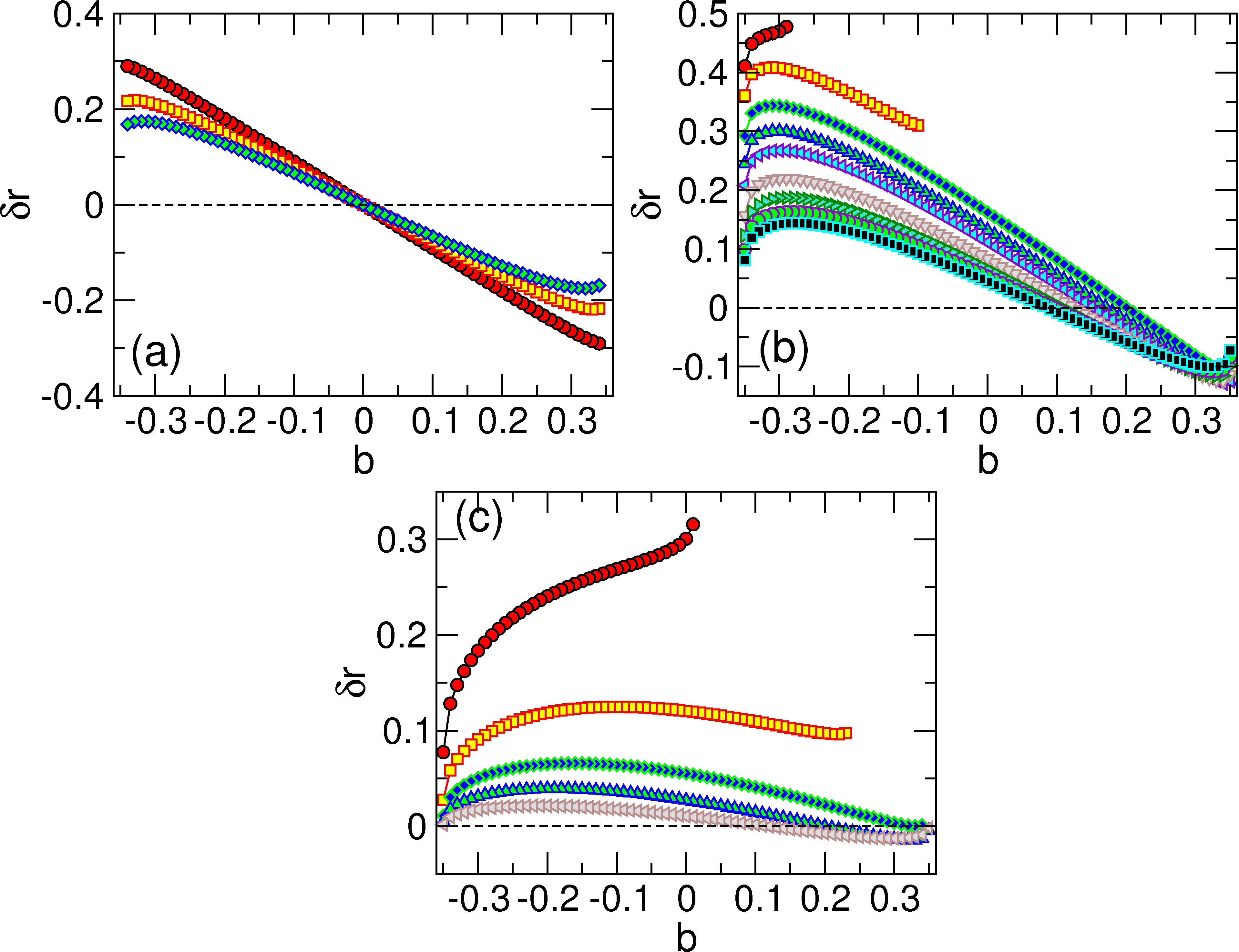
The trajectory shift δr vs impact parameter b
for a skyrmion moving through a pinning site with Fp = 0.1
and Rp = 0.35.
(a) αm/αd = 0 for FD=0.12, 0.16, and 0.20, from upper left to
lower left. δr is symmetric across b=0.
(b) αm/αd = 1.0
for FD=0.085, 0.09, 0.10, 0.11, 0.12, 0.14, 0.16,
0.18, and 0.20, from upper left to lower left.
Here the shift is asymmetric across b=0.
For values of b where there are no points, the skyrmion
is captured by the pinning site.
(b) αm/αd = 10
for FD=0.03, 0.05, 0.08, 0.12, and 0.20, from upper
left to lower left.
The shifts become larger with increasing αm/αd.
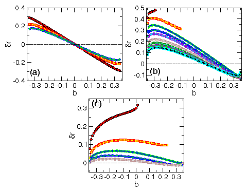
Figure 20:
The trajectory shift δr vs impact parameter b
for a skyrmion moving through a pinning site with Fp = 0.1
and Rp = 0.35.
(a) αm/αd = 0 for FD=0.12, 0.16, and 0.20, from upper left to
lower left. δr is symmetric across b=0.
(b) αm/αd = 1.0
for FD=0.085, 0.09, 0.10, 0.11, 0.12, 0.14, 0.16,
0.18, and 0.20, from upper left to lower left.
Here the shift is asymmetric across b=0.
For values of b where there are no points, the skyrmion
is captured by the pinning site.
(b) αm/αd = 10
for FD=0.03, 0.05, 0.08, 0.12, and 0.20, from upper
left to lower left.
The shifts become larger with increasing αm/αd.
|