New Journal of Physics 18, 095005 (2016)

Noise Fluctuations and Drive Dependence of the Skyrmion Hall Effect in Disordered Systems

C. Reichhardt and C. J. Olson Reichhardt

Theoretical Division and Center for Nonlinear Studies, Los Alamos National Laboratory, Los Alamos, New Mexico 87545, USA

Keywords: skyrmions, Hall effect, velocity noise, dynamic phase transitions
Received 26 July 2016
Revised 23 August 2016
Accepted for publication 6 September 2016
Published 29 September 2016

Abstract

Using a particle-based simulation model, we show that quenched disorder creates a drive-dependent skyrmion Hall effect as measured by the change in the ratio R=V/V|| of the skyrmion velocity perpendicular (V) and parallel (V||) to an external drive. R is zero at depinning and increases linearly with increasing drive, in agreement with recent experimental observations. At sufficiently high drives where the skyrmions enter a free flow regime, R saturates to the disorder-free limit. This behavior is robust for a wide range of disorder strengths and intrinsic Hall angle values, and occurs whenever plastic flow is present. For systems with small intrinsic Hall angles, we find that the Hall angle increases linearly with external drive, as also observed in experiment. In the weak pinning regime where the skyrmion lattice depins elastically, R is nonlinear and the net direction of the skyrmion lattice motion can rotate as a function of external drive. We show that the changes in the skyrmion Hall effect correlate with changes in the power spectrum of the skyrmion velocity noise fluctuations. The plastic flow regime is associated with 1/f noise, while in the regime in which R has saturated, the noise is white with a weak narrow band signal, and the noise power drops by several orders of magnitude. At low drives, the velocity noise in the perpendicular and parallel directions is of the same order of magnitude, while at intermediate drives the perpendicular noise fluctuations are much larger.
1. Introduction
2. Results and discussion
3. Summary
References

1.  Introduction

Skyrmions in magnetic systems are particle-like objects predicted to occur in materials with chiral interactions [1]. The existence of a hexagonal skyrmion lattice in chiral magnets was subsequently confirmed in neutron scattering experiments [2] and in direct imaging experiments [3]. Since then, skyrmion states have been found in an increasing number of compounds [4, 5, 6, 7, 8], including materials in which skyrmions are stable at room temperature [9, 10, 11, 12, 13, 14]. Skyrmions can be set into motion by applying an external current [15, 16], and effective skyrmion velocity versus driving force curves can be calculated from changes in the Hall resistance [17, 18] or by direct imaging of the skyrmion motion [9, 14]. Additionally, transport curves can be studied numerically with continuum and particle based models [19, 20, 21, 22, 23]. Both experiments and simulations show that there is a finite depinning threshold for skyrmion motion similar to that found for the depinning of current-driven vortex lattices in type-II superconductors [24, 25, 26]. Since skyrmions have particle like properties and can be moved with very low driving currents, they are promising candidates for spintronic applications [27, 28], so an understanding of skyrmion motion and depinning is of paramount importance. Additionally, skyrmions represent an interesting dynamical system to study due to the strong non-dissipative effect of the Magnus force they experience, which is generally very weak or absent altogether in other systems where depinning and sliding phenomena occur.
For particle-based representations of the motion of objects such as superconducting vortices, a damping term of strength αd aligns the particle velocity in the direction of the net force acting on the particle, while a Magnus term of strength αm rotates the velocity component in the direction perpendicular to the net force. In most systems studied to date, the Magnus term is very weak compared to the damping term, but in skyrmion systems the ratio of the Magnus and damping terms can be as large as αmd  ∼ 10 [17, 19, 21, 29]. One consequence of the dominance of the Magnus term is that under an external driving force, skyrmions develop velocity components both parallel (V||) and perpendicular (V) to the external drive, producing a skyrmion Hall angle of θsk = tan−1(R), where R=|V/V|||. In a completely pin-free system, the intrinsic skyrmion Hall angle has a constant value θskint = tan−1md); however, in the presence of pinning a moving skyrmion exhibits a side jump phenomenon in the direction of the drive so that the measured Hall angle is smaller than the clean value [22, 23, 30]. In studies of these side jumps using both continuum and particle based models for a skyrmion interacting with a single pinning site [22] and a periodic array of pinning sites [30], R increases with increasing external drive until the skyrmions are moving fast enough that the pinning becomes ineffective and the side jump effect is minimized.
Particle-based studies of skyrmions with an intrinsic Hall angle of θintsk=84° moving through random pinning arrays show that θsk=40° at small drives and that θsk increases with increasing drive until saturating at θskintsk for high drives [23]. In recent imaging experiments performed in the single skyrmion limit [31] it was shown that R=0 and θsk=0 at depinning and that both quantities increase linearly with increasing drive; however, the range of accessible driving forces was too low to permit observation of a saturation effect. These experiments were performed in a regime of relatively strong pinning, where upper limits of R  ∼ 0.4 and θsk = 20° are expected. A natural question is how universal the linear behavior of R and θsk is as a function of drive, and whether the results remain robust for larger intrinsic values of θsk. It is also interesting to ask what happens in the weak pinning limit where the skyrmions form a hexagonal lattice and depin elastically. In studies of overdamped systems such as superconducting vortices, it is known that the strong and weak pinning limits are separated by a transition from elastic to plastic depinning and have very different transport curve characteristics [24, 26], so a similar phenomenon could arise in the skyrmion Hall effect. Noise fluctuations have also been used as another method to study the dynamics of magnetic systems [32]. In superconducting vortex systems, the plastic flow regime is associated with large voltage noise fluctuations of 1/fα form [33, 34, 35, 36], while when the system dynamically orders at higher drives, narrow band noise features appear and the noise power is strongly reduced [26, 37, 38, 39]. Here we show that changes in the skyrmion Hall angle are correlated with changes in the skyrmion velocity fluctuations and the shape of the velocity noise spectrum. In the plastic flow region where R increases linearly with drive, there is a 1/fα velocity noise signal with α = 1.0, while when R reaches its saturation value, there is a crossover to white noise or weak narrow band noise, indicating that noise measures could provide another way to probe skyrmion dynamics. In general, we find that the narrow band noise features are much weaker in the skyrmion case than in the superconducting vortex case due to the Magnus effect.
Simulation and System- We consider a 2D simulation with periodic boundary conditions in the x and y-directions using a particle-based model of a modified Thiele equation recently developed for skyrmions interacting with random [21, 23] and periodic [30, 40] pinning substrates. The simulated region contains N skyrmions, and the time evolution of a single skyrmion i at position ri is governed by the following equation:
αd vi + αm
^
z
 
×vi = Fssi + Fspi + FD .
(1)
Here, the skyrmion velocity is vi = d ri/dt, αd is the damping term, and αm is the Magnus term. We impose the condition αd2 + αm2 = 1 to maintain a constant magnitude of the skyrmion velocity for varied αmd. The repulsive skyrmion-skyrmion interaction force is given by Fssi = ∑Nj=1 K1(rij) rij where rij=|rirj|, rij=(rirj)/rij, and K1 is a modified Bessel function that falls off exponentially for large rij. The pinning force Fspi arises from non-overlapping randomly placed pinning sites modeled as harmonic traps with an amplitude of Fp and a radius of Rp = 0.3 as used in previous studies [23]. The driving force FD=FD x is from an applied current interacting with the emergent magnetic flux carried by the skyrmion [17, 29]. We increase FD slowly to avoid transient effects. In order to match the experiments, we take the driving force to be in the positive x-direction so that the Hall effect is in the negative y-direction. We measure the average skyrmion velocity V||=〈N−1iN vi ·x〉 (V=〈N−1iN vi ·y〉) in the direction parallel (perpendicular) to the applied drive, and we characterize the Hall effect by measuring R = |V/V||| for varied FD. The skyrmion Hall angle is θsk = tan−1R. We consider a system of size L=36 with a fixed skyrmion density of ρsk=0.16 and pinning densities ranging from np=0.00625 to np=0.2.
Fig1.png
Figure 1: (a) The skyrmion velocities in the directions parallel (|V|||, blue) and perpendicular (|V|, red) to the driving force vs FD in a system with αmd = 5.708, Fp = 1.0, and np = 0.1. The drive is applied in the x-direction. Inset: a blowup of the main panel in the region just above depinning where there is a crossing of the velocity-force curves. (b) The corresponding R = |V/V||| vs FD. The solid straight line is a linear fit and the dashed line is the clean limit value of R=5.708. Inset: θsk = tan−1(R) vs FD. The dashed line is the clean limit value of θsk=80.06°.

2.  Results and discussion

In Fig. 1(a,b) we plot |V|, |V|||, and R versus FD for a system with Fp = 1.0, np = 0.1, and αmd = 5.708. In this regime, plastic depinning occurs, meaning that at the depinning threshold some skyrmions can be temporarily trapped at pinning sites while other skyrmions move around them. The velocity-force curves are nonlinear, and |V| increases more rapidly with increasing FD than |V|||. The inset of Fig. 1(a) shows that |V||| > |V| for FD < 0.1, indicating that just above the depinning transition the skyrmions are moving predominantly in the direction of the driving force. In Fig. 1(b), R increases linearly with increasing FD for 0.04 < FD < 0.74, as indicated by the linear fit, while for FD > 0.74 R saturates to the intrinsic value of R=5.708 marked with a dashed line. The inset of Fig. 1(b) shows the corresponding θsk versus FD. From an initial value of 0°, θsk increases with increasing FD before saturating at the clean limit value of θsk=80.06°. Although the linear increase in R with FD is similar to the behavior observed in the experiments of Ref. [31], θsk does not show the same linear behavior as in the experiments; however, we show later that when the intrinsic skyrmion Hall angle is small, θsk varies linearly with drive. We note that the experiments in Ref. [31] were performed in the single skyrmion limit rather than in the many skyrmion plastic flow limit we study. This could impact the behavior of the Hall angle, making it difficult to directly compare our results with these experiments.
Fig2.png
Figure 2: Skyrmion positions (dots) and trajectories (lines) obtained over a fixed time period from the system in Fig. 1(a). The drive is in the positive x-direction. (a) At FD = 0.02, R = 0.15 and the motion is mostly along the x direction. (b) At FD = 0.05, R = 0.6 and the flow channels begin tilting into the −y direction. (c) At FD = 0.2, R = 1.64 and the channels tilt further toward the −y direction. (d) Trajectories obtained over a shorter time period at FD = 1.05 where R = 5.59. The skyrmions are dynamically ordered and move at an angle of −79.8° to the drive.
In Fig. 2 we illustrate the skyrmion positions and trajectories obtained during a fixed period of time at different drives for the system in Fig. 1. At FD = 0.02 in Fig. 2(a), R = 0.15 and the average drift is predominantly along the x-direction parallel to the drive, taking the form of riverlike channels along which individual skyrmions intermittently switch between pinned and moving states. In Fig. 2(b), for FD = 0.05 we find R=0.6, and observe wider channels that begin to tilt along the negative y-direction. At FD = 0.2 in Fig. 2(c), R = 1.64 and θsk = 58.6°. The skyrmion trajectories are more strongly tilted along the −y direction, and there are still regions of temporarily pinned skyrmions coexisting with moving skyrmions. As the drive increases, individual skyrmions spend less time in the pinned state. Figure 2(d) shows a snapshot of the trajectories over a shorter time scale at FD = 1.05 where R = 5.59. Here the plastic motion is lost and the skyrmions form a moving crystal translating at an angle of −79.8° with respect to the external driving direction, which is close to the clean value limit of θsk. In general, the deviations from linear behavior that appear as R reaches its saturation value in Fig. 1(b) coincide with the loss of coexisting pinned and moving skyrmions, and are thus correlated with the end of plastic flow.
Fig3.png
Figure 3: 
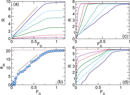
(a) R vs FD for samples with Fp = 1.0 and np = 0.1 at αmd = 9.962, 7.7367, 5.708, 3.042, 1.00, and 0.3737, from left to right. The line indicates a linear fit. (b) θsk = tan−1(R) for αmd = 0.3737 from panel (a). The solid line is a linear fit and the dashed line indicates the clean limit value of θsk = 20.5°. (c) R vs FD for αmd = 5.708 at Fp = 0.06125, 0.125, 0.25, 0.5, 0.75, and 1.0, from left to right. (d) R vs FD for Fp = 1.0 at αmd = 5.708 for np = 0.00617, 0.01234, 0.02469, 0.04938, 0.1, and 0.2, from left to right. The clean limit value of R is indicated by the dashed line.
In Fig. 3(a) we show R versus FD for the system from Fig. 1 at varied αmd. In all cases, between the depinning transition and the free flowing phase there is a plastic flow phase in which R increases linearly with FD with a slope that increases with increasing αmd. In contrast to the nonlinear dependence of θsk on FD at αmd=5.71 illustrated in the inset of Fig. 1(b), Fig. 3(b) shows that for αmd = 0.3737, θsk increases linearly with FD and θskint = 20.5, To understand the linear behavior, consider the expansion of tan−1(x) = xx3/3 + x5/5 ... For small αmd, as in the experiments, tan−1(R)  ∼ R, and since R increases linearly with FD, θsk also increases linearly with FD. In general, for αmd < 1.0 we find an extended region over which θsk grows linearly with FD, while for αmd > 1.0, the dependence of θsk on FD has nonlinear features similar to those shown in the inset of Fig. 1(b). In Fig. 3(c) we plot R versus FD for a system with αmd = 5.708 for varied Fp. In all cases R increases linearly with FD before saturating; however, for increasing Fp, the slope of R decreases while the saturation of R shifts to higher values of FD. In general, the linear behavior in R is present whenever Fp is strong enough to produce plastic flow. In Fig. 3(d) we show R versus FD at αmd = 5.708 for varied pinning densities np. In each case, there is a region in which R increases linearly with FD, with a slope that increases with increasing np. As np becomes small, the nonlinear region just above depinning where R increases very rapidly with drive becomes more prominent.
Fig4.png
Figure 4: (a) Depinning force Fc (circles) and fraction P6 of six-fold coordinated particles (squares) vs Fp for a system with αmd = 5.708 and np=0.1, showing a crossover from elastic depinning for Fp < 0.04 to plastic depinning for Fp ≥ 0.04. (b) R vs FD for a system in the elastic depinning regime with Fp = 0.01 and np = 0.1 at αmd = 9.962, 7.7367, 5.708, 3.042, and 1.00, from top to bottom. Circles indicate the case αmd = 5.708, for which the dashed line is a fit to R ∝ (FDFc)β with β = 0.26 and the dotted line indicates the pin-free value of R = 5.708. (c) R vs FD for samples with αmd = 5.708 and np=0.1 at Fp = 0.005, 0.01, 0.02, 0.03, 0.04, and 0.05, from left to right. The solid symbols correspond to values of Fp for which plastic flow occurs, while open symbols indicate elastic flow. The line shows a linear dependence of R on FD for Fp = 0.04.
For weak pinning, the skyrmions form a triangular lattice and exhibit elastic depinning, in which each skyrmion maintains the same neighbors over time. In Fig. 4(a) we plot the critical depinning force Fc and the fraction P6 of sixfold-coordinated skyrmions versus Fp for a system with np = 0.1 and αmd = 5.708. For 0 < Fp < 0.04, the skyrmions depin elastically. In this regime, P6 = 1.0 and Fc increases as FcFp2 as expected for the collective depinning of elastic lattices [25]. For Fp ≥ 0.04, P6 drops due to the appearance of topological defects in the lattice, and the system depins plastically, with FcFp as expected for single particle depinning or plastic flow.
In Fig. 4(b) we plot R versus FD in samples with Fp = 0.01 and np=0.1 in the elastic depinning regime for varied αmd. We highlight the nonlinear behavior for the αmd = 5.708 case by a fit of the form R ∝ (FDFc)β with β = 0.26 and Fc = 0.000184. The dotted line indicates the corresponding clean limit value of R=5.708. We find that R is always nonlinear within the elastic flow regime, but that there is no universal value of β, which ranges from β = 0.15 to β = 0.5 with varying αmd. The change in the Hall angle with drive is most pronounced just above the depinning threshold, as indicated by the rapid change in R at small FD. This results from the elastic stiffness of the skyrmion lattice which prevents individual skyrmions from occupying the most favorable substrate locations. In contrast, R changes more slowly at small FD in the plastic flow regime, where the softer skyrmion lattice can adapt to the disordered pinning sites. In Fig. 4(c) we plot R versus FD at αmd = 5.708 and np=0.1 for varied Fp, showing a reduction in R with increasing Fp. A fit of the Fp = 0.04 curve in the plastic depinning regime shows a linear increase of R with FD, while for Fp < 0.04 in the elastic regime, the dependence of R on FD is nonlinear. Just above depinning in the elastic regime, the skyrmion flow direction rotates with increasing drive.
Correlations Between Noise Fluctuations and the Skyrmion Hall Effect
The power spectrum of the velocity noise fluctuations at different applied drives represents another method that can be used to probe the dynamics of driven condensed matter systems. In the superconducting vortex case, the total noise power over a particular frequency range or the overall shape of the noise power spectrum can be determined by measuring the voltage time series at a particular current. Both experiments and simulations have shown that in the plastic flow regime, where the vortex flow is disordered and consists of a combination of pinned and flowing particles, the low frequency noise power is large and the voltage noise spectrum has a 1/fα character with 1.0 ≤ α ≤ 2.0. In contrast, the low frequency noise power is considerately reduced in the elastic or ordered flow regime, where the noise is either white with α = 0 or exhibits a characteristic washboard frequency associated with narrow band noise. Based on these changes in the noise characteristics, it is possible to map out a dynamical phase diagram for the vortex system.
In the skyrmion system, the Hall resistance can be used to detect the motion of skyrmions, and therefore, in analogy with the voltage response in a superconductor, fluctuations in the Hall resistance at a specific applied current should reflect fluctuations in the skyrmion velocity. Since the recent experiments of Ref. [31] used imaging techniques to measure R, it is desirable to understand whether changes in R are correlated with changes in the fluctuations of other quantities. We measure the time series of V||(t) and V(t) in samples with αmd = 5.71, Fp = 1.0, and np = 0.1, the same parameters used in Figs. 1 and 2. For these values, R increases linearly with increasing FD over the range 0.01 < FD < 0.8 before saturating close to the clean value. For each value of FD, we then construct the power spectrum
S(ω) =

V||,⊥(t)eiωtdt
2
 
,
(2)
where FD is held constant during an interval of 1.7×10⁵ simulation time steps.
Fig5.png
Figure 5: The power spectrum S(ω) of the skyrmion velocity fluctuations obtained from time series of V|| (blue) and V (red) for the system in Fig. 1 at αmd = 5.71, Fp = 1.0, and np = 0.1. (a) At FD = 0.05, both spectra are similar in magnitude. (b) At FD = 0.4, deep in the plastic flow regime, the noise power is largest for V, for which S(ω) has a 1/ωα form with α = 1.0, as indicated by the green line. (c) At FD = 1.05 in the saturation regime, both spectra are white with α = 0, as indicated by the green line.
In Fig. 5(a) we plot S(ω) for V||(t) and V(t) at FD = 0.05 in the plastic flow regime. Here, the spectral shape is very similar in each case, while the noise power at low frequencies is slightly higher for V|| than for V. At FD=0.4 in Fig. 5(b), deep in the plastic flow phase, the noise power is much higher for V than for V|| and can be fit reasonably well to a ω−1 form, while V|| also has an ω−1 shape over a less extended region. The two spectra have equal power only for high ω. Figure 5(c) shows S(ω) at FD = 1.05, which corresponds to the saturation region of R. The V signal still has the highest spectral power, but both spectra now exhibit a white or ω0 shape. There is a small bump at low frequency which is more prominent in V|| that may correspond to a narrow band noise feature. We note that in the overdamped limit of αmd = 0 at this same drive, where the particles have formed a moving lattice, there is a strong narrow band noise feature, suggesting that the Magnus term is responsible for the lack of a strong narrow band noise peak in Fig. 5(c). In general, we find that the power spectrum for the skyrmions shows 1/ω noise in the plastic flow regime and white noise in the saturation regime.
Fig6.png
Figure 6: The noise power S0, determined by the value of S(ω) at a fixed frequency of ω = 50, vs FD for V|| (blue circles) and V (red squares) for the system in Fig. 5 plotted along with R (green line) from Fig. 1, showing that the noise power drops when R saturates.
Using the power spectrum, we can calculate the noise power S0 at a specific value of ω. In Fig. 5 we plot S0=S(ω = 50) for V|| and V versus FD, along with the corresponding R curve from Fig. 1. At low FD, the value of S0 is nearly the same for both V|| and V. The noise power for V increases more rapidly with increasing FD and both S0 curves reach a maximum near FD = 0.5 before decreasing as R reaches its saturation value. In general S0 is large whenever the spectrum has a 1/ω shape. This result shows that noise power fluctuations could be used to probe changes in the skyrmion Hall effect and even dynamical transitions from plastic to elastic skyrmion flow.
We note that in real skyrmion systems, the skyrmions can also have internal modes of motion that could affect the noise power. Such internal modes are not captured by the particle model, and would likely occur at much higher frequencies than those of the skyrmion center of of mass motion that we analyze here. It would be interesting to see if such modes arise in experiment and to determine whether they can also modify the skyrmion Hall angle.

3.  Summary

We have investigated the skyrmion Hall effect by measuring the ratio R of the skyrmion velocity perpendicular and parallel to an applied driving force. In the disorder-free limit, R and the skyrmion Hall angle take constant values independent of the applied drive; however, in the presence of pinning these quantities become drive-dependent, and in the strong pinning regime R increases linearly from zero with increasing drive, in agreement with recent experiments. For large intrinsic Hall angles, the current-dependent Hall angle increases nonlinearly with increasing drive; however, for small intrinsic Hall angles such as in recent experiments, both the current-dependent Hall angle and R increase linearly with drive as found experimentally. The linear dependence of R on drive is robust for a wide range of intrinsic Hall angle values, pinning strengths, and pinning densities, and appears whenever the system exhibits plastic flow. For weaker pinning where the skyrmions depin elastically, R has a nonlinear drive dependence and increases very rapidly just above depinning. We observe a crossover from nonlinear to linear drive dependence of R as a function of the pinning strength, which coincides with the transition from elastic to plastic depinning. We also show how R correlates with changes in the power spectra of the velocity noise fluctuations both parallel and perpendicular to the drive. In the plastic flow regime where R increases linearly with increasing FD, we find 1/f noise that crosses over to white noise at higher drives. The noise power drops dramatically as R saturates at high drives.

  Acknowledgements

We gratefully acknowledge the support of the U.S. Department of Energy through the LANL/LDRD program for this work. This work was carried out under the auspices of the NNSA of the U.S. DoE at LANL under Contract No. DE-AC52-06NA25396.

References

[1]
Rößler U K, Bogdanov A N and Pfleiderer C 2006 Nature (London) 442 797
[2]
Mühlbauer S, Binz B, Jonietz F, Pfleiderer C, Rosch A, Neubauer A, Georgii R and Böni P 2009 Science 323 915
[3]
Yu X Z, Onose Y, Kanazawa N, Park J H, Han J H, Matsui Y, Nagaosa N and Tokura Y 2010 Nature (London) 465 901
[4]
Heinze S, von Bergmann K, Menzel M, Brede J, Kubetzka A, Wiesendanger R, Bihlmayer G and Blulgel S 2011 Nature Phys. 7 713
[5]
Yu X Z, Kanazawa N, Onose Y, Kimoto K, Zhang W Z, Ishiwata S, Matsui Y and Tokura Y 2011 Nature Mater. 10 106
[6]
Seiki S, Yu X Z, Ishiwata S and Tokura Y 2012 Science 336 198
[7]
Shibata K, Yu X Z, Hara T, Morikawa D, Kanazawa N, Kimoto K, Ishiwata S, Matsui Y and Tokura Y 2013 Nature Nanotechnol. 8 723
[8]
Kézsmárki I 2015 Nature Mater. 14 1116
[9]
Jiang W, Upadhyaya P, Zhang W, Yu G, Jungfleisch M B, Fradin F Y, Pearson J E, Tserkovnyak Y, Wang K L, Heinonen O, te Velthuis S G E and Hoffmann A 2015 Science 349 283
[10]
Chen G, Mascaraque A, N'Diaye A T and Schmid A K 2015 Appl. Phys. Lett. 106 242404
[11]
Tokunaga Y, Yu X Z, White J S, Rønnow H M, Morikawa D, Taguchi Y and Tokura Y 2015 Nature Commun. 6 7638
[12]
Moreau-Luchaire C, Moutaļ¬s C, Reyren N, Sampaio J, Vaz C A F, Van Horne N, Bouzehouane K, Garcia K, Deranlot C, Warnicke P, Wohlhüter P, George J-M, Weigand M, Raabe J, Cros V and Fert A 2016 Nature Nanotechnol. 11 444
[13]
Boulle O, Vogel J, Yang H, Pizzini S, de Souza Chaves D, Locatelli A, Mentes T O, Sala A, Buda-Prejbeanu L D, Klein O, Belmeguenai M, Roussigné Y, Stashkevich A, Chérif S M, Aballe L, Foerster M, Chshiev M, Auffret S, Miron I M and Gaudin G 2016 Nature Nanotechnol. 11 449
[14]
Woo S, Litzius K, Krüger B, Im M, Caretta L, Richter K, Mann M, Krone A, Reeve R, Weigand M, Agrawal P, Lemesh I, Mawass M, Fischer P, Kläui M and Beach G 2016 Nature Mater. 15 501
[15]
Jonietz F, Mühlbauer S, Pfleiderer C, Neubauer A, Münzer W, Bauer A, Adams T, Georgii R, Böni P, Duine R A, Everschor K, Garst M and Rosch A 2010 Science 330 1648
[16]
Yu X Z, Kanazawa N, Zhang W Z, Nagai T, Hara T, Kimoto K, Matsui Y, Onose Y and Tokura Y 2012 Nature Commun. 3 988
[17]
Schulz T, Ritz R, Bauer A, Halder M, Wagner M, Franz C, Pfleiderer C, Everschor K, Garst M and Rosch A 2012 Nature Phys. 8 301
[18]
Liang D, DeGrave J P, Stolt M J, Tokura Y and Jin S 2015 Nature Commun. 6 8217
[19]
Iwasaki J, Mochizuki M and Nagaosa N 2013 Nature Commun. 4 1463
[20]
Iwasaki J, Mochizuki M and Nagaosa N 2013 Nature Nanotechnol. 8 742
[21]
Lin S-Z, Reichhardt C, Batista C D and Saxena A 2013 Phys. Rev. B 87 214419
[22]
Müller J and Rosch A 2015 Phys. Rev. B 91 054410
[23]
Reichhardt C, Ray D and Reichhardt C J O 2015 Phys. Rev. Lett. 114 217202
[24]
Bhattacharya S and Higgins M J 1993 Phys. Rev. Lett. 70 2617
[25]
Blatter G, Feigelman M V, Geshkenbein V B, Larkin A I and Vinokur V M 1994 Rev. Mod. Phys. 66 1125
[26]
Olson C J, Reichhardt C and Nori F 1998 Phys. Rev. Lett. 81 3757
[27]
Fert A, Cros V and Sampaio J 2013 Nature Nanotechnol. 8 152
[28]
Tomasello R, Martinez E, Zivieri R, Torres L, Carpentieri M and Finocchio G 2014 Sci. Rep. 4 6784
[29]
Nagaosa N and Tokura Y 2013 Nature Nanotech. 8 899
[30]
Reichhardt C, Ray D and Reichhardt C J O 2015 Phys. Rev. B 91 104426
[31]
Jiang W, Zhang X, Yu G, Zhang W, Jungfleisch M B, Pearson J E, Heinonen O, Wang K L, Zhou Y, Hoffmann A and te Velthuis S G E arXiv:1603.07393 (unpublished).
[32]
Weissman M B 1988 Rev. Mod. Phys. 60 537
[33]
Marley A C, Higgins M J and Bhattacharya S 1995 Phys. Rev. Lett. 74 3029
[34]
Rabin M, Merithew R, Weissman M, Higgins M J and Bhattacharya S 1998 Phys. Rev. B 57 R720
[35]
Olson C J, Reichhardt C and Nori F 1998 Phys. Rev. Lett. 80 2197
[36]
Kolton A, Domínguez D and Grønbech-Jensen N 1999 Phys. Rev. Lett. 83 3061
[37]
Maeda A, Tsuboi T, Abiru R, Togawa Y, Kitano H, Iwaya K and Hanaguri T 2002 Phys. Rev. B 65 054506
[38]
Okuma S, Inoue J and Kokubo N 2007 Phys. Rev. B 76 172503
[39]
Mangan N, Reichhardt C and Reichhardt C J O 2008 Phys. Rev. Lett. 100 187002
[40]
Reichhardt C and Reichhardt C J O 2015 Phys. Rev. B 92 224432


File translated from TEX by TTHgold, version 4.00.
Back to Home