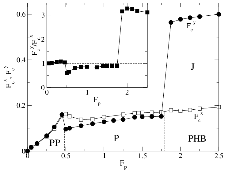
Physical Review B 78, 224511 (2008)

Moving Vortex Phases, Dynamical Symmetry Breaking, and Jamming for Vortices in Honeycomb Pinning Arrays

C. Reichhardt and C.J. Olson Reichhardt

Theoretical Division, Los Alamos National Laboratory, Los Alamos, New Mexico 87545, USA

(Received 16 July 2008; revised manuscript received 6 November 2008; published 9 December 2008)

We show using numerical simulations that vortices in honeycomb pinning arrays can exhibit a remarkable variety of dynamical phases that are distinct from those found for triangular and square pinning arrays. In the honeycomb arrays, it is possible for the interstitial vortices to form dimer or higher n-mer states which have an additional orientational degree of freedom that can lead to the formation of vortex molecular crystals. For filling fractions where dimer states appear, a novel dynamical symmetry breaking can occur when the dimers flow in one of two possible alignment directions. This leads to transport in the direction transverse to the applied drive. We show that dimerization produces distinct types of moving phases which depend on the direction of the driving force with respect to the pinning lattice symmetry. When the dimers are driven along certain directions, a reorientation of the dimers can produce a jamming phenomenon which results in a strong enhancement in the critical depinning force. The jamming can also cause unusual effects such as an increase in the critical depinning force when the size of the pinning sites is reduced.
I. INTRODUCTION
II. SIMULATION
III. DYNAMICS AND TRANSVERSE RESPONSE FOR DRIVING IN THE LONGITUDINAL DIRECTION
A. Finite Size Effects
B. Fluctuations and Noise Characteristics
C. Dynamical Symmetry Breaking in the Pinned Phase
D. Dynamics for 1.5 ≤ B/Bϕ < 2.5
E. Effect of Changing the Pinning Strength
F. Changing Rp and Bϕ
G. Effect of Finite Temperature
IV. DYNAMICS FOR DRIVING IN THE TRANSVERSE DIRECTION
A. Dynamics as a function of Fp and Dimer Jamming
B. Effects of Changing Rp and Bϕ
V. DISCUSSION
VI. SUMMARY
References


I.  INTRODUCTION

Vortex matter in type-II superconductors has been extensively studied as a unique system of many interacting particles in which nonequilibrium phase transitions can be accessed readily [1,2,3,4,5,6,7,8,9]. In the absence of driving or quenched disorder, the vortex-vortex interactions favor a triangular crystalline ordering. If the sample contains sufficiently strong quenched disorder in the form of randomly placed pinning sites, the vortex lattice ordering can be lost as the vortices adjust their positions to accommodate to the pinning landscape [1,2,3,4]. Under an applied drive such as the Lorentz force from a current, the vortices remain immobile or pinned for low driving forces; however, there is a threshold applied force above which the vortices begin to move over the quenched disorder. For strong disorder, the initial moving state is highly inhomogeneous with the vortices flowing in meandering and fluctuating channels, and there is a coexistence between pinned vortices and flowing vortices [2,3]. At higher drives the vortices move more rapidly, the effectiveness of the quenched disorder is reduced, and the fluctuations experienced by the vortices become anisotropic due to the directionality of the external drive [5]. The vortex-vortex interactions become more important at the higher drives when the quenched disorder becomes ineffective, and a dynamical transition can occur into a moving smectic state where the vortices regain partial order in one direction [6,7,8]. Here, the system has crystalline order in the direction transverse to the vortex motion and liquid-like order in the direction of vortex motion. Depending on the dimensionality and the strength of the pinning, it is also possible for the vortices to reorganize in both directions at high drives to form a moving anisotropic crystal [5,6,7,8,9,10]. The existence of these different phases and transitions between the phases can be inferred from signatures in transport [4] and noise fluctuations [11,12], and the moving phases have also been imaged directly using various techniques [8,9].
In addition to the naturally occurring randomly placed pinning sites, it is also possible for artificial pinning sites to be created in a periodic structure [13]. Recent advances in nanostructuring permit the creation of a wide variety of periodic pinning landscapes where the periodicity, shape, size and density of the pinning sites can be well controlled. Distinct types of pinning arrays such as square [14,15,16,17,18,19,20,21] triangular [22,23], rectangular [24,25], honeycomb [26,27], kagomé [26], quasicrystalline [28], and partially ordered [29] structures have been created. In these arrays the type of vortex structure that forms is determined by whether the vortex lattice is commensurate with the underlying pinning array. Commensurate arrangements appear at integer multiples of the matching field Bϕ, which is the magnetic field at which the vortex density matches the pinning density, and in general, ordered vortex states occur at matching or rational fractional values of B/Bϕ [14,15,16,30,31,32,33]. In samples where only one vortex can be captured by each pinning site, the vortices that appear above the first matching field sit in the interstitial regions between the pinning sites, and these interstitial vortices can adopt a variety of crystalline configurations [15,16,17,18,20,25,30,31,33].
Since a number of distinct ordered and partially ordered vortex states can be created in periodic pinning arrays, a much richer variety of dynamical vortex behaviors occur for periodic pinning than for random pinning arrays [16,17,18,34,35,36,37,38,39,40,41,42,43,44,45,46,47,48,49,50]. Several of the dynamical phases occur due to the existence of highly mobile interstitial vortices which channel between the pinned vortices [16,18,36,37,38,40,41,43,44,46,50]. As a function of applied drive, various types of moving phases occur, including interstitial vortices moving coherently between the pinning sites in one-dimensional paths [16,18,34,35,37,36,40,44] or periodically modulated winding paths [34,36,45,46], disordered regimes where the vortex motion is liquidlike [34,36,40,44], and regimes where vortices flow along the pinning rows [34,39,47,48,49]. Other dynamical effects, such as rectification of mixtures of pinned and interstitial vortices, can be realized when the periodic pinning arrays are asymmetric [50].
Fig1.png
Figure 1: (a) Pinning site locations (open circles) for a triangular pinning array. (b) Pinning site locations for a honeycomb pinning array constructed from the triangular array in (a) by removing 1/3 of the pinning sites. (c) The pinning site locations and vortex positions (dots) for a honeycomb pinning array at B/Bϕ = 1.5. The overall vortex lattice order is triangular. (d) The pinning site locations and vortex positions for a honeycomb pinning array at B/Bϕ = 2.0, where two vortices are captured at the large interstitial sites and the resulting dimers all have the same orientation. Here Fp = 0.85, Rp = 0.35λ, and for the honeycomb array np = 0.3125/λ2.
Most of the studies of vortex ordering and dynamics in periodic pinning arrays have been performed for square and triangular arrays. Experiments with honeycomb and kagomé pinning arrays revealed interesting anomalies in the critical current at nonmatching fields which are as pronounced as the anomalies observed at matching fields in triangular pinning arrays [26,27]. A honeycomb pinning array is constructed by removing every third pinning site from a triangular pinning array, producing a periodic arrangement of triangular interstitial sites. In Figs. 1(a,b) we illustrate a triangular pinning array along with the honeycomb pinning array that results after the removal of one third of the pinning sites. The matching anomalies in the experiments coincide with fields B/Bϕ=m/2, with m an integer. At these fields, the vortex density would match with the regular triangular pinning array. At the matching anomalies for m > 2, a portion of the vortices are located in the large interstitial regions of the honeycomb lattice [27], as illustrated in Fig. 1(c) for B/Bϕ = 1.5. The overall vortex lattice structure is triangular and a strong peak in the depinning force occurs at this field [51].
Recently, we used numerical simulations to demonstrate that vortices in honeycomb pinning arrays have a rich equilibrium phase diagram as a function of vortex density [51], with matching anomalies at integer and half integer matching fields that are in agreement with experiments. The large interstitial sites created by the missing pinning sites can capture multiple interstitial vortices which form cluster states of n vortices. For 1.5 ≤ B/Bϕ < 2.5, dimer states with n=2 form, while for higher fields trimer and higher order n-mer states form. At the integer and half-integer matching fields, the n-mer states can assume a global orientational ordering which may be of ferromagnetic or antiferromagnetic type; herringbone structures can also form, similar to those observed for colloidal particles on periodic substrates [52,53,54,55,56] and molecules on atomic substrates [57]. These orientationally ordered states have been termed vortex molecular crystals. Certain vortex molecular crystals have ground states that are doubly or triply degenerate, such as the dimer state illustrated in Fig. 1(d) at B/Bϕ = 2.0 where the dimers align in one of three equivalent directions [51]. As the temperature is increased, the n-mers undergo a transition from an ordered state to an orientationally disordered state in which the n-mers rotate randomly but remain confined to the interstitial pinning sites. The rotating states have been termed vortex plastic crystals. At matching fields where vortex plastic crystals form, the anomalies in the critical current disappear [51]. The predictions from the simulations are in general agreement with the experimental observation of the loss of certain higher order matching anomalies at higher temperatures [27]. The formation of n-mers that can be aligned along degenerate symmetry directions has also been predicted for kagomé pinning arrays where every other pinning site is removed from every other row of a triangular lattice [51,58].
The formation of dimer states in the honeycomb pinning array leads to a variety of novel dynamical phases, including a spontaneous dynamical symmetry breaking effect in which the moving vortices organize into one of two equivalent states which have a component of translation perpendicular to the applied drive in either the positive or negative direction [59]. The transverse response appears when the external driving force is applied halfway between the two symmetric directions of aligned dimer motion. The dynamical symmetry breaking occurs when the equilibrium ground states have no global symmetry breaking. At B/Bϕ = 2.0, the ground state is symmetry broken and the dynamical moving state has the same broken symmetry as the ground state. For incommensurate fillings, when the dimer alignment is disrupted, there is no global symmetry breaking in the ground state, and instead a dynamical symmetry breaking occurs due to the applied drive.
In this work we map the dynamical phase diagram for vortices in honeycomb arrays. We focus on the states 1.5 < B/Bϕ < 2.5 to understand where dynamical symmetry breaking occurs and to examine what other types of moving phases are possible. We study how the dynamical phases change for driving along different axes of the pinning lattice. We find that very different types of dynamics occur when the driving direction is varied, and that the value of the depinning threshold is strongly directionally dependent. We also find that a novel jamming phenomenon can occur due to the formation of the dimer states. For certain directions of drive, the dimers are anti-aligned with the drive, causing the dimers to become blocked in the interstitial regions.
Although our results are specifically for vortices in type-II superconductors, the general features of this work should also be relevant for other interacting particle systems where a periodic substrate is present. Examples of such systems include vortices on periodic substrates in Bose-Einstein condensates (BEC) where different types of crystalline phases can occur depending on the strength of the substrate [60,61]. It should be possible to observe different types of vortex flow states in BEC systems [62]. Our results are also relevant for colloids on periodic substrates, where an orientational ordering of colloidal molecular crystals occurs which is very similar to that of the vortex molecular crystal states [52,53,54,55,56,63]. Other related systems include charged balls on periodic substrates [64] and models of sliding friction [65].

II.  SIMULATION

We use the same simulation model employed in the previous study of vortex equilibrium states in honeycomb pinning arrays [51]. We consider a two-dimensional system of size Lx=L and Ly=L with periodic boundary conditions in the x and y directions. The sample contains Nv vortices, giving a vortex density of nv = Nv/L2 which is proportional to the external magnetic field. In addition, there are Np pinning sites placed in a honeycomb arrangement with a pinning density of np=Np/L2. The field at which the number of vortices equals the number of pinning sites is defined to be the matching field Bϕ.
The dynamics of vortex i located at position Ri is governed by the following overdamped equation of motion:
η d Ri

dt
= Fvvi + Fvpi + FD + FiT.
(1)
Here the damping constant is η = ϕ20d/2πξ2 ρN, where d is the thickness of the superconducting sample, ξ is the superconducting coherence length, ρN is the normal state resistivity of the material, and ϕ0 = h/2e is the elementary flux quantum. The vortex-vortex interaction force is
Fvvi = Nv

ji 
f0K1
Rij

λ

^
R
 

ij 
(2)
where K1 is the modified Bessel function, λ is the London penetration depth, f0 = ϕ20/(2πμ0λ3), Rij=|RiRj| is the distance between vortex i and vortex j, and the unit vector Rij = (RiRj)/Rij. In this work all length scales are measured in units of λ and forces in units of fo. The vortex vortex interaction decreases sufficiently rapidly at large distances that a long range cutoff is placed on the interaction force at Rij = 6λ to permit more efficient computation times. The cutoff creates a small discontinuity in the vortex-vortex interaction force which ideally could be lessened by the addition of a function that goes to zero smoothly; however, since the Bessel function falls off very rapidly, the discontinuity is very small at 6λ. In past studies we have found that longer range cutoffs produce only negligible differences and that an interaction range of 6λ is adequate [30,31,34,51]. Other studies with logarithmically interacting vortices and no interaction range cutoff produced a similar set of commensurate states and dynamical vortex states in periodic pinning arrays as those obtained for the Bessel function interaction with a cutoff [35,36,37], giving us reason to believe that our interaction range cutoff does not affect our overall results.
The pinning force Fvpi originates from individual nonoverlapping attractive parabolic traps of radius Rp which have a maximum strength of Fp. In this work we consider the limit where only one vortex can be captured per pinning site, with the majority of the results obtained for Rp = 0.35λ. The exact form of the pinning force is:
Fvpi = − Np

k=1 
f0
Fp

Rp

Rik(p)Θ
RpRik(p)

λ

^
R
 
(p)
ik 
.
(3)
Here, Rik(p)=|RiRk(p)|, R(p)k is the location of pinning site k, the unit vector R(p)ik = (RiRk(p))/Rik(p), and Θ is the Heaviside step function.
The external drive FD=FDf0FD represents the Lorentz force from an applied current J×B which is perpendicular to the driving force and is applied uniformly to all the vortices. We apply the drive at various angles to the symmetry axes of the honeycomb pinning array. The thermal force FiT originates from Langevin kicks with the properties 〈FiT〉 = 0 and 〈FiT(t)FjT(t′)〉 = 2ηkBT δijδ(tt′). Unless otherwise noted, the thermal force is set to zero. The initial vortex configurations are obtained by simulated annealing, and the external force is then applied gradually in increments of ∆FD=0.0002 every 1000 simulation time steps. For the range of pinning forces used in this work, we find that this force ramp rate is sufficiently slow that transients in the vortex dynamics do not affect the overall velocity-force curves. We obtain the velocity-force curves by summing the velocities in the x (longitudinal) direction, 〈Vx〉 = Nv−1Nvi=1 vi·x, and the y (transverse) direction, 〈Vy〉 = Nv−1Nvivi·y, where vi = dRi/dt. In Fig. 1(c,d) we illustrate the pinning sites and vortex configurations after simulated annealing for B/Bϕ = 1.5 [Fig. 1(c)] and 2.0 [Fig. 1(d)]. Here Lx=Ly = 24λ and np = 0.3125/λ2. In our previous work, Ref. [59], the drive was applied along the x-direction for the geometry in Fig. 1.

III.  DYNAMICS AND TRANSVERSE RESPONSE FOR DRIVING IN THE LONGITUDINAL DIRECTION

Fig2.png
Figure 2: (a) The average velocity in the x-direction 〈Vx〉 vs external driving force FD for the honeycomb pinning array from Fig. 1(d) at B/Bϕ = 2.0 with FD=FDx. (b) The corresponding average velocity in the y-direction 〈Vy〉 vs FD. We observe four phases: the initial pinned phase (P), a symmetry broken phase (SB), a random phase (R), and a moving locked phase (ML).
Fig3.png
Figure 3: The dynamics of the three moving phases from Fig. 2 for the honeycomb pinning array at B/Bϕ=2.0 with FD=FDx. The vortex positions (filled circles), pinning site locations (open circles), and vortex trajectories (black lines) are shown in an 18λ×18λ portion of the sample. (a) In the symmetry broken (SB) phase at FD = 0.25, the interstitial vortices move along a −30° angle to the x-axis while the vortices at the pinning sites remain immobile. (b) Vortex positions only in the SB phase at FD=0.25, showing the ordering present in the vortex lattice structure. (c) In the random (R) phase at FD = 0.42, the vortex motion is highly disordered with vortices pinning and repinning at random. (d) Vortex positions only in the R phase at FD=0.42 indicate that the vortex lattice is disordered. (e) In the moving locked (ML) phase at FD = 0.65, all the vortices channel along the pinning sites. (f) Vortex positions only in the ML phase at FD=0.65 reveal an anisotropic vortex lattice structure with different numbers of vortices in each row.
We first consider the case for driving in the x or longitudinal direction, FD=FDx, for the system shown in Fig. 1(d) with B/Bϕ = 2.0, Rp = 0.35λ, and Fp = 0.85. In Figs. 2(a,b) we plot 〈Vx〉 and 〈Vy〉 versus FD. At this filling there are four distinct dynamical phases, with the pinned (P) phase occurring at low FD. The depinning threshold Fc occurs near FD = 0.14 when the interstitial vortices become depinned. For a system with random pinning and FD=FDx, there would be no transverse velocity response; the system would have 〈Vy〉 = 0 and only 〈Vx〉 would be finite. In contrast, for the honeycomb pinning array there is a finite velocity both in the positive x direction and in either the +y or −y direction. In Fig. 2(b) the transverse response 〈Vy〉 is negative, indicating that the vortices are moving at a negative angle to the x axis for 0.14 < FD < 0.37. Figure 3(a) illustrates the vortex motion at FD=0.25, where the vortices flow in one-dimensional paths oriented at −30° to the x axis. In Fig. 3(b) a snapshot of the vortex positions shows that the vortex lattice remains ordered in the moving phase, indicating that the vortices are flowing in a coherent manner. We term the phase shown in Fig. 3(a) the symmetry broken (SB) phase, since the flow can be tilted in either the positive or negative y-direction.
At B/Bϕ = 2.0 and FD = 0, the interstitial vortices form an aligned dimer configuration with a three-fold degenerate ground state in which the dimers can be oriented along the y-direction, as in Fig. 1(d), or along +30° or −30° to the x-direction, as shown in previous work [59]. When a driving force is applied to the +30° or −30° ground states, the vortices depin and flow along +30° or −30°, respectively. In these cases, the symmetry breaking in the moving state is not dynamical in nature but reflects the symmetry breaking within the ground state. If the dimers are initially aligned along the y-direction in the ground state, an applied drive induces an instability in the pinned phase and causes the dimers to rotate into the +30° or −30° directions, as we discuss in further detail below. In this case the symmetry breaking is dynamical in origin.
Fig4.png
Figure 4: Time traces of vortex velocity at fixed FD. Upper curves: Vx(t); lower curves: Vy(t). (a) The symmetry broken (SB) phase at FD = 0.25 from Fig. 3(a,b). Here pronounced oscillations occur in both Vx and Vy as the vortices move in a coherent fashion. (b) The random (R) phase at FD = 0.42 from Fig. 3(c,d). In this case the transverse motion is lost and 〈Vy〉 = 0. Additionally, there are no correlated oscillations. (c) The moving locked (ML) phase at FD = 0.65 from Fig. 3(e,f). Vx has been shifted down for clarity. There is a weak oscillation in Vx due to the periodic substrate. Since the flow is strictly one-dimensional, as shown in Fig. 3(e), there are no fluctuations in Vy.
In Fig. 2(a,b) we find pronounced oscillations in both 〈Vx〉 and 〈Vy〉 just above the depinning threshold Fc=0.14. These oscillations are not intrinsic features but are due to the fact that at B/Bϕ = 2.0 the interstitial vortex lattice is perfectly ordered, so the interstitial vortices move in a coherent fashion as shown in Fig. 3(a). At depinning, the interstitial vortices are slowly moving through a periodic potential created by vortices that remain trapped at the pinning sites. This periodic potential causes the moving interstitial vortices to develop an oscillating velocity. In Fig. 4(a), the instantaneous time traces of the vortex velocity Vx and Vy at constant FD = 0.25 show strong velocity oscillations. At incommensurate fields, there is enough dispersion in the velocity of the moving interstitial vortices that the coherent velocity oscillations are no longer distinguishable.
As FD increases, the net vortex velocity in the SB phase increases linearly until FD = 0.365, where there is an abrupt increase in 〈Vx〉. Fig. 2(a,b) shows that this increase coincides with a jump in 〈Vy〉 to a zero average, indicating that the vortices are moving only in the x-direction on average. In Fig. 3(c) we illustrate the disordered vortex trajectories that occur in this phase at FD = 0.42. The vortices are continually depinning and being repinned, and the order in the vortex lattice is lost, as shown in Fig. 3(d). We term this the random (R) phase. It resembles random dynamical phases that have previously been observed for vortices in square pinning arrays when the interstitial vortices begin to depin vortices from the pinning sites [30]. Figure 2 shows that there are pronounced random fluctuations in 〈Vx〉 and 〈Vy〉 in phase R, and also that 〈Vx〉 does not increase linearly with FD but has a curvature consistent with Vx = (FDFRc)1/2, where FRc=0.365 is the threshold value for the SB-R transition. In the SB phase, the number of moving vortices is constant and is equal to the number of interstitial vortices, while in the R phase the number of moving vortices increases with FD.
At FD = 0.53, the system organizes into a one-dimensional flowing state where the vortex motion is locked along the pinning rows, as shown in Fig. 3(e,f) for FD = 0.65. The onset of this phase also coincides with the decrease of fluctuations in 〈Vx〉 and the loss of fluctuations in Vy, as shown in Fig. 4(c). For FD > 0.53, all of the vortices are mobile and Fig. 2(a) illustrates that the 〈Vx〉 versus FD curve becomes linear again. We term this the moving locked (ML) phase, since the vortex motion is effectively locked along the pinning sites. When the vortices are rapidly moving, the pinning sites have the same effect as a flashing one-dimensional trough that channels the vortices [34,39]. The vortices assume a smectic structure in the ML phase, since different rows have different numbers of vortices, resulting in the formation of aligned dislocations. The ML phase is essentially the same state found in square pinning arrays at high drives when B/Bϕ > 1.0 [34].
In previous studies of square pinning arrays with strong pinning, the initial motion of the vortices for B/Bϕ > 1.0 occurred in the form of one-dimensional channels between the vortices trapped at the pinning sites [34]. In the honeycomb pinning array, similar flow occurs in the SB phase as shown in Fig. 3(a). For B/Bϕ < 1.5 in the honeycomb array, the initial interstitial flow for depinning in the x direction occurs via the flow of individual vortices in a zig-zag pattern around the pinned vortices. Since there is no dimer ordering for these fillings, no transverse response occurs for B/Bϕ < 1.5. For B/Bϕ ≥ 1.5, the interstitial vortices begin to form dimer states when two interstitial vortices are captured in a single large interstitial site. The dimers can lower their orientational energy by aligning with each other in both the ground state and the moving states. Dimers can only remain aligned in the moving state if they are channeling along one of the symmetry axes of the pinning lattice. If the dimers were to move strictly in the x-direction, they would be forced directly into the pinned vortex in the pinning site to the right of each large interstitial site. This would destabilize the rodlike dimers. Instead, the dimers maintain their integrity by moving along ±30° to the x-axis. Within the moving state, if one of the dimers were to move along +30° while the remaining dimers were moving along −30°, the two interstitial vortices comprising the first dimer would be forced close together, destabilizing the dimer state due to the repulsive vortex-vortex interactions. Instead, all of the dimers move in the same direction.
The SB-R transition occurs when the combined forces on the pinned vortices from the external drive and the moving dimers are strong enough to depin the pinned vortices. At the closest approach in the x direction between a dimer and a pinned vortex, the frontmost dimer vortex is a distance a0/2 from the pinned vortex and the rear dimer vortex is a distance 3a0 from the pinned vortex, where ao is the lattice constant of the undiluted triangular pinning lattice. In addition to the force from the dimerized vortices, the pinned vortex experiences an opposing force from the neighboring pinned vortex a distance a0 away. In a simple approximation, the driving force needed to depin a vortex at a pinning site is thus FD = Fp − [(K1(a0/2) + K1(3a0/2)) − K1(a0)]. Setting Fp = 0.85 gives FD = 0.41, close to the value of FD = 0.37 for the SB-R transition in Fig. 2. Once the pinned vortices depin, the system enters the random (R) phase, and since FD is still considerably less than Fp, it is possible for vortices to be pinned temporarily in phase R.
Studies of square pinning arrays have shown that after the onset of a random dynamical phase, the vortices can organize into a more ordered phase of solitonlike pulse motion along the pinning rows, followed by a phase in which all of the vortices channel along the pinning rows [34]. At the transition to the one-dimensional pulse like motion, a larger fraction of the vortices are pinned compared to the random phase, so a drop in 〈Vx〉 with increasing FD occurs, giving a negative differential conductivity. In the honeycomb pinning arrays for the parameters we have chosen here, we do not observe one-dimensional pulse motion or negative differential conductivity for driving along the x-direction. For the one-dimensional pulse motion or the ML phase motion seen in Fig. 3(e,f) to occur, the vortices must be moving at a sufficiently high velocity for the pinning sites to act like a flashing trough. When the vortices move along the pinning rows, the vortex lattice structure adopts a highly anisotropic configuration which would be unstable at FD=0. During the period of time when a vortex passes through a pinning site, the vortex is pulled toward the center of the pinning row, which stabilizes the one-dimensional motion. When the vortex is moving between the pinning sites, it can drift away from the one-dimensional path until it encounters another pinning site. In Ref. [34], it was shown that for square pinning arrays, increasing the pinning radius Rp stabilized the one-dimensional flow down to lower values of FD. In the honeycomb pinning array, the one-dimensional flow is less stable due to the fact that the vortices must move over the much wider large interstitial site, giving the vortices more time to drift away from the pinning row. Since this means that a larger value of FD is required to stabilize the one-dimensional motion, it should be more difficult in general to observe the onset of one-dimensional solitonlike motion or negative differential conductivity in the honeycomb pinning arrays than in the square pinning arrays.
Fig5.png
Figure 5: The absolute value of the transverse velocity |Vy| versus time for systems with Fp=0.85, Rp=0.35λ, np=0.3125/λ2, and B/Bϕ = 1.81. At time t=0 a longitudinal drive of FD=0.3 is suddenly applied. From left to right, the system sizes are L = 24λ, 36λ, and 60λ.
Fig6.png
Figure 6: The vortex positions (filled circles), pinning site locations (open circles), and vortex trajectories (black lines). (a,b,c) The evolution of the vortex trajectories into the SB phase after application of a drive FD=0.3 for the system in Fig. 5 at B/Bϕ=1.81 with L = 24λ. (a) The initial motion of the system at t=3000 simulation time steps where the net transverse velocity 〈Vy 〉 is near zero. (b) The partial organization of the SB phase at t=40000 simulation time steps. (c) The complete organization of the SB phase for t=160000 simulation time steps. At later times the system remains in the state illustrated in panel (c). (d) The vortex trajectories in the SB state for the L = 60λ system at B/Bϕ = 2.0.

A.  Finite Size Effects

We next consider the effect of the system size on the SB phase, since it might be expected that the SB phase could be more readily stabilized in a small system. We perform simulations with the same parameters as in Fig. 2 but for larger systems with L = 36λ and L=60λ. For all system sizes at B/Bϕ = 2.0 and for sufficiently long annealing times, we find a state similar to that shown in Fig. 1(d), where all the dimers align in one of the three directions. Once the system is in a broken symmetry ground state, it depins directly into a SB state and moves along a +30° or −30° angle to the x-axis. For fillings very close to B/Bϕ = 2.0, the global symmetry of the ground state is preserved and the system still depins directly into one of the +30° or −30° moving configurations. For fillings further away from commensuration, the dimer state becomes disordered and the dimers move simultaneously along both the +30° and −30° directions, giving an initial transverse velocity of |Vy| ≈ 0. Over time, the system dynamically organizes into either the +30° or −30° moving state. To illustrate this, we consider a system with B/Bϕ=1.81 and abruptly increase the driving force from FD=0 to FD=0.3, a value at which the moving SB phase should be stable. This procedure is similar to the one we used in previous work where we found that the initial transverse velocity of | Vy | ≈ 0 asymptotically approached either a positive or negative finite value over time [59]. In Fig. 5 we plot |Vy| versus time after the sudden application of a drive FD=0.3 at t=0 for samples of sizes L = 24λ, 36λ, and 60λ with B/Bϕ = 1.81. The system always organizes into a SB state with finite 〈Vy〉; however, the time required to reach the SB state increases with increasing system size L. In Fig. 6(a-c) we illustrate the evolution of the vortex trajectories into the SB state for the L=24λ sample at B/Bϕ=1.81. Vortices initially move in both the +30° and −30° directions, as seen in Fig. 6(a), but gradually a larger fraction of the vortices move in the +30° direction, as shown in Fig. 6(b), until finally all of the vortices organize into the +30° direction and form the moving SB state shown in Fig. 6(c). In Fig. 6(d) we show the SB state for L = 60λ at B/Bϕ = 2.0 where the system passes immediately from the pinned ordered ground state into the moving SB state without any transient period. The increasing time required for the system to reach the SB state for increasing system sizes at incommensurate fields implies that in an infinite system, a true SB state may never be reached at the incommensurate fields; however, since |Vy| is generally increasing with time, the presence of the SB phase could be deduced by measuring a time dependent transverse velocity response for a fixed longitudinal drive. We note that the time dependence of the transverse velocity at the incommensurate fields implies that new types of memory or coarsening effects could be studied with this system, which is beyond the scope of this work. If we consider the system to be similar to an Ising model, the sudden application of a longitudinal drive would be equivalent to suddenly quenching the Ising system into a zero magnetic field state. The system will coarsen over time into a positive or negative magnetic field state, and this process will take longer for larger systems.
The n-merization effect for interstitial vortices in honeycomb pinning arrays [51] is very similar to the colloidal molecular crystal states studied for colloids on periodic substrates [52,53,54,55,56]. In both cases it is possible to have a ferromagnetic-like coupling between the dimers or n-mers. Theoretical work on the colloidal molecular crystals indicates that many of the states of these systems can be mapped to Ising or n-state Potts models [54,55,56], which are known to have ordered ground states. If the dimerized interstitial vortices also fall into this class of systems, we would expect the ground state at B/Bϕ = 2.0 to have a global ordering that is independent of the system size. For the static vortex system, there are three possible ordered ground states rather than two, but in the presence of an applied drive there are only two ordered moving states. Although the driven state is nonequilibrium, it could still be considered as a dynamical type of Ising model with two global dynamical low energy states that are independent of the system size. As indicated earlier, if the dimers are moving in two different directions at the same time, they must approach each other much more closely, which is energetically unfavorable. We note that in our previous work, we showed that the moving SB states are highly stable and that once the system locks into a moving SB state, an appreciable external force must be applied to switch the system out of the state [59].
Any real superconducting system is likely to contain some random disorder, which could interfere with the formation of the SB state. We have shown, however, that the system can still organize into a SB state even for incommensurate fields, which are intrinsically disordered. Therefore, we expect that the SB state should still be accessible even in the presence of random quenched disorder, provided that the disorder is not too strong. Since the SB states at B/Bϕ = 2.0 are the most strongly ordered, this is the best applied field to consider when seeking to measure the transverse response in the SB phase experimentally.
The symmetry breaking in the system considered here arises due to particle-particle interactions between the vortex dimers, while the underlying substrate is symmetric. In transverse ratchet systems, where an applied ac or dc longitudinal driving force produces an additional transverse response, symmetry breaking is triggered by an asymmetric substrate, and the particle-particle interactions are irrelevant. [66,67,68,69]. The direction of the transverse motion in transverse ratchets is determined by the direction of the substrate asymmetry. In contrast, for vortex dimers in a honeycomb pinning array, the transverse response can be in either direction depending on how the symmetry breaks in the ground state configuration at B/Bϕ = 2.0 or upon the formation of the dynamical SB state.
Fig7.png
Figure 7: The power spectra S(ν) of the x component of the velocity Vx(t) for the three phases in Fig. 4. (a) The SB phase at FD=0.25 shows a pronounced narrow band noise signature. (b) The R phase at FD=0.42 has a broad band noise signature. (c) In the ML phase at FD=0.65, a number of different frequencies are present due to the fact that different rows of the vortices move at different velocities.

B.  Fluctuations and Noise Characteristics

In order to characterize the moving phases more quantitatively, in Fig. 4 we show time traces Vx(t) and Vy(t) of the vortex velocities at fixed FD for the different phases for the system in Fig. 2. In the symmetry broken (SB) phase at FD=0.25, shown in Fig. 4(a), Vx is greater than |Vy| by tan(30°) or about 1.7. Here both components of the velocity show a pronounced oscillation which arises when the interstitial vortices move in a coherent fashion over the periodic potential substrate created by the immobile vortices in the pinning sites. In Fig. 7(a), we plot the corresponding power spectrum S(ν) of Vx obtained from
S(ν) =

Vx(t)e−2πiνtdt
2
 
.
(4)
There is a pronounced peak in S(ν) at the frequency of the velocity oscillation in the SB phase, indicating that mode locking effects could appear at B/Bϕ = 2.0 when the symmetry breaking flow occurs. In square pinning arrays, experiments [18] and simulations [37] revealed Shapiro step-like mode locking of interstitial moving vortices at B/Bϕ = 2.0. In the honeycomb lattice, since there is also a strong oscillation in Vy in the SB phase, we expect that transverse mode locking could occur if an additional ac drive is applied in the y-direction. Such mode locking would appear as steps in both 〈Vx〉 and 〈Vy〉 versus FD in the SB phase. Transverse phase locking, which produces steps that are distinct from Shapiro steps, has been observed for the motion of vortices in square arrays [38]. In general, if the vortices already have an intrinsic velocity oscillation in the transverse direction, then pronounced transverse phase locking is possible.
In Fig. 4(b) we plot the time trace of Vx and Vy for the random (R) phase at FD = 0.42. In this case 〈Vy〉 = 0, and although both Vx and Vy show fluctuations, no oscillations or washboard frequencies appear. In Fig. 7(b) we show the corresponding S(ν) for Vx, where we find a broad band noise feature consistent with disordered plastic flow [4,7,12]. Since there are no coherent velocity oscillations, mode locking should be absent in the random (R) phase.
In Fig. 4(c) we plot Vx and Vy in the ML phase at FD = 0.65, where Vx has been shifted down by a factor of 3 for clarity. There are no visible fluctuations in Vy due to the one-dimensional nature of the flow, but there are small periodic oscillations in Vx generated by the motion of the vortices over the periodic substrate. Due to the fact that different one-dimensional rows contain different numbers of vortices, producing dispersion in the vortex velocities, the oscillation in Vx is not as pronounced as in the SB phase. The corresponding power spectrum in Fig. 7(c) contains a rich variety of peaks due to the wide range of frequencies present in this phase. The main peak is smaller in magnitude than that found for the SB phase. As FD increases, the frequency at which the first peak occurs also increases. It should be possible to generate phase locking in the ML phase; however, it would likely not be as pronounced as in the SB phase. These results suggest that noise fluctuations can be a useful technique for exploring the presence of different dynamical phases in periodic pinning arrays.
Fig8.png
Figure 8: Vortex positions (filled circles), pinning site locations (open circles), and trajectories (black lines) for a system with B/Bϕ = 2.0 and Fp = 0.85 which started in the y-aligned ground state. (a) The pinned phase at FD = 0.09. Here the dimers and the vortices in the pinning sites have all shifted slightly to the right compared to the ground state due to the applied drive. (b) A rotational instability occurs at FD ≈ 0.11, when the vortices move in a manner that allows the dimers to align along −30° to the x-axis. There is also a small shift of the vortices in the pinning sites. (c) The pinned state at FD = 0.12 where the dimers are aligned in the new −30° direction.
Fig9.png
Figure 9: The velocity 〈Vx〉 (upper curve) and 〈Vy〉 (lower curve) vs FD for the system in Fig. 8. The rotational instability seen in Fig. 8(b) appears as a positive peak in 〈Vx〉 and a negative peak in 〈Vy〉 just above FD = 0.11. The system remains pinned until around FD = 0.14.

C.  Dynamical Symmetry Breaking in the Pinned Phase

As previously noted, the ground state at B/Bϕ = 2.0 is three-fold degenerate. When the dimers are aligned at either +30° or −30° to the x-axis in the ground state, the subsequent SB flow is aligned in the same direction as the ground state. It is also possible for the dimers to align in the y-direction, as shown in Fig. 8(a). At FD = 0.09, the dimers and the vortices in the pinning sites are shifted slightly to the right due to the applied drive. As FD is further increased, a symmetry breaking transition occurs within the pinned phase. For FD < 0.11 the dimers remain aligned the y-direction; however, at FD ≈ 0.11, the rotational instability illustrated in Fig. 8(b) occurs. The dimers rotate in such a way that they end up aligned in the −30° direction. The interstitial vortex at the bottom of the dimer moves in the +x direction and by a smaller amount in the +y direction, while the vortex at the top of the dimer moves in the −y direction and by a smaller amount in the −x direction. There is also a slight shift of the vortices in the pinning sites that are closest to the bottom of each dimer. In Fig. 8(c) the rotation process is completed and the dimers are aligned in a new direction, −30°. The vortices remain pinned until FD = 0.14, at which point the system enters the SB phase. At finite temperatures, the dimer realignment occurs at even lower values of FD. The rearrangement can also be observed as a jump in 〈Vx〉 and 〈Vy〉 as shown in Fig. 9, where there is a positive spike in 〈Vx〉 and a negative spike in 〈Vy 〉 near FD = 0.11, in agreement with the motion shown in Fig. 8(b). We term this a dimer polarization effect since the driving force induces an alignment of the dimers. In runs with slightly different initial conditions, the dimers may align along the +30° direction with 50% probability.
Fig10.png
Figure 10: Vortex positions (filled circles) and pinning site locations (open circles) for the system in Fig. 2 at (a) B/Bϕ = 1.91 and (b) B/Bϕ = 2.08. At these fillings, the long range orientational ordering of the dimer state is lost.

D.  Dynamics for 1.5 ≤ B/Bϕ < 2.5

We next consider the effect of changing the vortex density for fillings where interstitial dimers are present and the SB phase occurs. In Fig. 10(a) we illustrate the vortex positions for B/Bϕ = 1.91, where a mixture of monomers and dimers appear in the large interstitial sites. At this filling, the overall orientational ordering of the dimers is lost in the ground state, and the dimers are oriented only in local patches. For B/Bϕ > 2.0, a mixture of interstitial dimers and trimers is present, as shown in Fig. 10(b) for B/Bϕ = 2.08, and the orientational ordering is again lost. In Ref. [59] it was shown that the SB state still occurs at incommensurate fields as long as some dimers are present. If FD is suddenly increased from zero to a finite value at which only the interstitial vortices depin, the moving state for the incommensurate fields organizes into a dynamically symmetry broken state where all of the dimers flow along +30° or −30°. At the incommensurate fields, only the dimers undergo dynamical symmetry breaking; the monomers and trimers continue to move in the direction of the drive, with some fluctuations in the transverse direction.
Fig11.png
Figure 11: 〈Vy〉 versus FD for (a) B/Bϕ = 1.89, (b) B/Bϕ = 1.94, and (c) B/Bϕ = 2.5 for a system with the same parameters as in Fig. 2. P: pinned phase; SB: symmetry broken phase; R: random phase; ML: moving locked phase.
In Fig. 11 we plot 〈Vy〉 for the system in Fig. 2 at B/Bϕ = 1.89, 1.94, and 2.5. In Figs. 11(a,b), the same four phases described above are labeled. The SB phase has opposite sign in Fig. 11(a) and Fig. 11(b); the dynamical symmetry breaking can occur in either direction since there is no symmetry breaking in the ground state. If slightly different initial conditions are used, such as by changing the initial annealing procedure, the dynamical symmetry breaking has equal probability to occur in the positive or negative direction, as shown previously [59]. In Figs. 11(a) and (b) the initial portion of the SB phase has fluctuations in 〈Vy〉 due to the fact that we are increasing FD at a finite rate and there is a transient time for the moving state to fully organize into the SB state, as studied previously [59]. The transient time increases as |B/Bϕ−2.0| increases. If we decrease ∆FD, the fluctuations at depinning are reduced; however, the boundary between the phases does not shift.
In Fig. 11(c) at B/Bϕ=2.5, 〈Vy〉 = 0 since there are only trimer states present. The large oscillations in 〈Vy〉 occur when the system forms a completely ordered trimer ground state [51] and the vortex motion is highly coherent, similar to the effect seen in Fig. 2. For the rate at which we sample and average 〈Vy〉 versus FD, the periodic fluctuating vortex velocity is visible. For FD > 0.5 the system enters a partially moving locked phase where a portion of the vortices move along the pinning rows. There are, however, too many vortices to form straight one-dimensional chains of the type shown in Fig. 3(e) for B/Bϕ = 2.0. A buckling instability of the chains occurs since the amount of anisotropy that would occur if one-dimensional chains formed is too large for the vortex lattice to sustain. Instead, a partially moving locked (PML) phase forms with a disordered moving vortex lattice. This result is interesting since it indicates that moving vortex phases do not always organize into ordered states. A time trace of a PML state at fixed FD shows much weaker velocity oscillations than those shown in Fig. 4(c) for the ML state. This suggests that phase locking with PML states will be very weak or absent. In previous work on phase locking for square arrays, it was shown that the phase locking is most pronounced at commensurate fields where the moving vortex structures are more ordered [18,37].
Fig12.png
Figure 12: The dynamic phase diagram for FD vs B/Bϕ highlighting the different dynamical phases. P: pinned, SB: symmetry broken, R: random, ML: moving locked. Here Fp=0.85, Rp=0.35λ, and np=0.3125/λ2. For B/Bϕ > 2.125, at high FD the system forms a partially moving locked (PML) phase where not all of the vortices move along the pinning rows.
By performing a series of simulations for varied B/Bϕ, measuring the features in the velocity force curves and observing the vortex structures, we construct the dynamical phase diagram of FD vs B/Bϕ shown in Fig. 12. The depinning force marking the end of the pinned (P) phase shows peaks at B/Bϕ = 1.5, 2.0, and 2.5, corresponding to the commensurate and ordered ground states reported previously [51]. The SB-R transition line is fairly flat as a function of B/Bϕ with an enhancement to higher values of FD occurring near B/Bϕ = 2.0, while at the incommensurate fields, monomers or trimers create fluctuations that cause the vortices at the pinning sites to depin at slightly lower values of FD. For B/Bϕ < 2.1, upon increasing FD the random state organizes into a ML state where all the vortices move along the pinning rows as shown in Fig. 3(e), while for B/Bϕ ≥ 2.1, the random state organizes into the PML state. The width of the random phase, as determined by the fluctuations in the velocity, increases and persists to higher values of FD for increasing B/Bϕ at B/Bϕ ≥ 2.1. For B/Bϕ < 1.5 and Bϕ > 2.5, where dimers are no longer present, the SB phase is lost and a new set of dynamical phases arises which we discuss in more detail below.
Fig13.png
Figure 13: The critical depinning force Fc vs Fp for a system with B/Bϕ = 2.0, Rp=0.35λ, and np=0.3125/λ2. For Fp < 0.45 a partially pinned (PP) state forms which is illustrated in Fig. 14(a). For 0.45 ≤ Fp < 1.75 the system forms the pinned (P) orientationally ordered dimer state such as that shown in Fig. 1(c). For Fp ≥ 1.75, the pinned herringbone (PHB) state seen in Fig. 14(b) forms.
Fig14.png
Figure 14: Vortex positions (filled circles) and pinning site locations (open circles) for the system in Fig. 13. (a) The partially pinned (PP) state at Fp = 0.25. The vortex lattice structure consists of a triangular lattice, and only half of the pinning sites are occupied. (b) The pinned herringbone (PHB) state at Fp = 2.0. Here the dimers do not all align in the same direction, but instead alternate in their alignment from row to row.
Fig15.png
Figure 15: Vortex positions (filled circles), pinning site locations (open circles), and vortex trajectories for the system in Fig. 13. (a) Moving crystal (MC) state for Fp=0.25 and FD = 0.2. The partially pinned (PP) state from Fig. 14(a) depins elastically into a MC where half of the vortices move directly along the pinning rows and the other half of the vortices move in winding paths between the pinning sites. (b) Moving interstitial (MI) state for Fp=2.0 and FD = 0.225. The pinned herringbone (PHB) state depins into a MI state in which interstitial vortices move around the pinned vortices.

E.  Effect of Changing the Pinning Strength

We next consider the effect of changing the pinning strength when B/Bϕ = 2.0. The four phases in Fig. 2 occurred in a sample with Fp = 0.85. As Fp is varied, we find several different kinds of ordering within the pinned phase that affect the dynamics which occur at finite FD. In Fig. 13 we plot the threshold depinning force Fc as a function of Fp. For Fp < 0.35 the pinning is weak enough that the vortex-vortex interactions dominate over the pinning energy and a nearly triangular vortex lattice forms, as shown in Fig. 14(a). In this arrangement, half of the pinning sites are still occupied, so the vortex lattice is partially pinned (PP) and there is a finite depinning threshold. This type of partially pinned vortex lattice was observed in previous simulations on honeycomb pinning lattices [51], and similar partially pinned vortex lattice states have been predicted for square pinning arrays [33] and observed for metallic particles on periodic structures [64]. The depinning transition from the PP state is elastic, and all the vortices depin simultaneously to form the moving triangular crystal (MC) shown in Fig. 15(a). In the MC, half of the vortices move in one-dimensional paths along the pinning rows while the remaining vortices move through the interstitial regions with a small transverse oscillation.
Figure 13 shows that the pinned ordered dimer state (P) forms for 0.45 ≤ Fp < 1.75. Over the range 0.45 ≤ Fp < 0.55, the depinning from state P does not occur by the initial flow of the interstitial vortices into the SB phase, unlike the case shown earlier for Fp=0.85. Instead, for 0.45 ≤ Fp < 0.55, both the interstitial vortices and the vortices at the pinning sites depin simultaneously and rearrange into the moving crystal (MC) state shown in Fig. 15(a). We also find a peak in Fc at Fp=0.5. This peak occurs due to both the change in the pinning configuration and a change in the depinning process. For Fp < 0.45, only half of the pinning sites are occupied and the vortex lattice depins elastically. At 0.45 ≤ Fp < 0.55, all of the pinning sites are now occupied in the P state, but the vortex lattice still depins elastically. The pinning energy that must be overcome to depin the lattice is increased compared to the PP state, leading to an increase in Fc. For 0.55 ≤ Fp < 1.75, the depinning process is plastic and only the interstitial vortices flow at depinning to form the SB state. Since the plastic depinning process does not require pinned vortices to depin, the threshold force Fc drops, producing the peak in Fc at Fp=0.5.
For Fp ≥ 0.7 in Fig. 13, the depinning threshold Fc slowly increases with increasing Fp, and a transition in the pinned vortex structure occurs at Fp = 1.75. For Fp ≥ 1.75, the dimers in the pinned state are no longer aligned but form a pinned herringbone (PHB) type structure such as that shown in Fig. 14(b), where the dimers are tilted in the same direction in one row and tilted in the opposite direction in the adjacent rows. Herringbone ordering of dimers has previously been observed for colloidal dimers on triangular lattices [34] and for vortices in kagomé arrays at 5/3 filling [51]. At depinning, the PHB state does not form a SB phase but instead forms the winding interstitial phase shown in Fig. 15(b). The dimers break apart into two monomers, with one monomer passing around the pinned vortices in the positive y direction and the other monomer passing the pinned vortices in the negative y direction. We term this state the moving interstitial (MI) phase.
In contrast to the herringbone state, the aligned dimer or ferromagnetic ordering of the P state occurs when the pinned vortices adjacent to the dimers are able to undergo a periodic distortion within the pinning sites, reducing the interaction energy between the pinned and interstitial dimer vortices and permitting the dimer alignment. If the dimers are aligned along +30°, as in Fig. 5(a) of Ref. [51], the two pinned vortices closest to each interstitial vortex in the dimer both splay outwards away from the +30° direction. When Fp is increased, the pinned vortices are pulled toward the center of each pinning site and are no longer able to distort in order to accommodate the aligned dimer state, so the pinned herringbone (PHB) state forms instead. This result suggests that there may be other types of ground state ordering for vortices in honeycomb and kagomé arrays in addition to those that have been reported previously. It may be possible to use the size and shape of the pinning sites as a means of controlling the type of crystalline structure that forms.
Fig16.png
Figure 16: 〈Vx〉 vs FD for B/Bϕ = 2.0, Rp=0.35λ, and np=0.3125/λ2. (a) At Fp = 0.25, there is an elastic depinning transition between the partially pinned (PP) state and the moving crystal (MC) state. (b) At Fp = 1.125 the four dynamical phases are present. P: pinned; SB: symmetry broken; R: random; ML: moving locked. (c) At Fp = 2.125 the pinned herringbone (PHB) state depins into the moving interstitial (MI) state illustrated in Fig. 15(b). The transition between the MI and the moving locked (ML) state is much sharper than the R to ML transition shown in (b).
In Fig. 16, we plot 〈Vx〉 versus FD for Fp = 0.25, 1.125, and 2.125. Figure 16(a) shows the elastic depinning process for the PP state at Fp=0.25, which moves directly into the MC phase after depinning. At Fp = 1.125 in Fig. 16(b), 〈Vx〉 increases linearly with FD through the SB phase. The slope of 〈Vx〉 increases in the R phase, and the velocity-force relationship becomes linear in the ML phase. For Fp = 2.125, Fig. 16(c) indicates that the depinning occurs in two steps. The first depinning transition of the interstitial vortices only takes the system from the P phase into the moving interstitial (MI) phase, while at the second depinning transition, the pinned vortices depin and the sample enters the ML phase. Unlike the behavior at Fp=1.125 in Fig. 16(b), at Fp=2.125 the intermediate random (R) phase is lost and is replaced by a sharp jump into the ML phase.
Fig17.png
Figure 17: The dynamic phase diagram of FD vs Fp for B/Bϕ = 2.0, Rp=0.35λ, and np=0.3125/λ2. The three pinned phases are: PP, the partially pinned phase shown in Fig. 14(a); P, the pinned ordered dimer phase in Fig. 1(c); and PHB, the pinned herringbone phase illustrated in Fig. 14(b). The dashed line separates the moving crystal phase (MC) shown in Fig. 15(a) from the moving locked (ML) phase of Fig. 3(e). The symmetry broken (SB) phase illustrated in Fig. 3(a) occurs at intermediate vales of Fp, while the moving interstitial (MI) phase shown in Fig. 15(b) forms at higher values of Fp. The random (R) phase is illustrated in Fig. 3(c).
By conducting a series of simulations we construct the dynamical phase diagram as a function of Fp and FD, as shown in Fig. 17. At high FD, the MC phase forms for Fp < 0.45, while for Fp ≥ 0.45 the ML phase appears instead. The SB phase exists for 0.55 < Fp < 1.75, and the SB-R boundary shifts to higher FD with increasing Fp until it terminates at Fp = 1.75. For Fp ≥ 1.75, the PHB state occurs at low drive, and the system depins into the MI phase. The MI phase also extends as far down as Fp=1.5, where the system passes from the SB phase into a narrow window of the random (R) phase with increasing FD before the vortices organize into the MI phase. As FD continues to increase, the vortices at the pinning sites depin and the system passes through a second narrow window of the R phase until the vortices organize into the ML phase. At high Fp, the R phase becomes vanishingly small and the system passes directly from the MI to the ML phase. The transition into the ML state increases linearly with increasing Fp, while the depinning force saturates with increasing Fp.
Fig18.png
Figure 18: The dynamic phase diagram of FD vs Rp for B/Bϕ = 2.0 and Fp = 0.85. PP: partially pinned phase; P: pinned dimer phase; MI2: moving interstitial phase 2; SB: symmetry broken phase; R: random phase; MC: moving crystal phase; ML: moving locked phase. For Rp > 0.2λ we observe the same phases illustrated in Fig. 17 at Fp=0.85. The curves do not extend above Rp=0.55λ since for Rp > 0.55λ, multiple vortex pinning at individual pinning sites occurs. For Rp < 0.2λ, a partially pinned phase appears and the initial depinning is into a new moving interstitial phase termed MI2, illustrated in Fig. 19(a). The upper dashed line separates the MC phase from the ML phase.
Fig19.png
Figure 19: (a) Vortex positions (filled circles), pinning site locations (open circles) and vortex trajectories (black lines) for the system in Fig. 18 showing the moving interstitial 2 phase (MI2) at Rp = 0.15λ and Fp = 0.2. (b) 〈Vx〉 vs FD for the same system. A sharp transition from the MI2 phase to the random (R) phase occurs.

F.  Changing Rp and Bϕ

We next examine the effects of changing the pinning radius in a system with fixed Fp = 0.85 and B/Bϕ = 2.0. In Fig. 18 we show the dynamic phase diagram for FD versus Rp obtained from a series of simulations. For 0.2λ < Rp ≤ 0.55λ, we find the same three moving phases, SB, R, and ML, as in Fig. 2. For Rp > 0.55λ, the pins are large enough to permit double vortex occupancy at the individual pinning sites; in this case, a new set of phases appears which we do not consider in this work. For Rp > 0.2λ, the R-ML transition decreases in FD with increasing Rp since the larger pinning sites make it easier for the vortices to localize along the pinning rows and flow in the one-dimensional motion of the ML phase. For Rp < 0.2λ at low FD, we find the partially pinned PP state illustrated in Fig. 14(a). The onset of the PP phase coincides with a drop in Fc at Rp ≈ 0.2λ. Unlike the PP phase that occurs at low Fp in Fig. 17, which depins elastically, the PP phase at small Rp depins into a moving interstitial phase that is distinct from the moving interstitial phase shown in Fig. 15(b). In Fig. 19(a) we illustrate the vortex trajectories in the phase which we term the moving interstitial phase 2 (MI2). The vortices flow in winding interstitial channels; however, unlike the MI phase, in the MI2 phase only half of the pinning sites are occupied. In Fig. 19(b) we plot 〈Vx〉 vs FD for a system with Rp = 0.15λ. A clear two-step depinning transition occurs, with 〈Vx〉 increasing linearly with increasing FD in the MI2 phase. At high FD and Rp < 0.2λ, the pinning sites are too small for the ML phase to occur, and instead the vortices flow in the MC phase illustrated in Fig. 15(a).
Fig20.png
Figure 20: The dynamic phase diagram FD versus pinning density nv, which determines Bϕ, at B/Bϕ = 2.0, Fp = 0.85, and Rp = 0.35λ. P: pinned dimer phase; MI: moving interstitial phase; SB: symmetry broken phase; R: random phase; ML: moving locked phase. The transition to the ML phase shifts to higher FD with decreasing np. The SB phase appears only for intermediate values of np.
We next consider samples with fixed B/Bϕ = 2.0, Rp = 0.35λ, and Fp = 0.85, but vary the value of Bϕ by changing the pinning density np. This alters the average spacing between neighboring vortices. Up to this point we have used np=0.3125/λ2. In Fig. 20 we illustrate the dynamic phase diagram for FD versus np. As np increases, Fc increases since the depinning of the interstitial vortices is determined by the potential created by the vortices located at the pinning sites, and as the vortex density increases, the depth of the interstitial pinning potential also increases. The R-ML transition shifts to higher FD with decreasing np. Since the distance between the pinning sites increases with decreasing np, the moving vortices spend less time in the pinning sites. This destabilizes the ML phase and the vortices must move at higher velocities for the effective trough potential to be able to stabilize the ML phase. For np ≥ 0.78/λ2, the SB phase is lost, since at this pinning density the interactions between the interstitial vortices and the pinned vortices become sufficiently strong that the depinning of the interstitial vortices also causes the pinned vortices to depin. As a result, the system passes directly from the P phase to the R phase with increasing FD. For np < 0.14/λ2, the vortex-vortex interaction becomes weak enough that the system depins into the MI phase illustrated in Fig. 15(b). This also coincides with an increase in the value of FD at which the R phase appears, since the moving interstitial vortices in the MI phase do not approach the pinned vortices as closely as they do in the SB phase.
Fig21.png
Figure 21: The dynamic phase diagram of FD vs thermal force FT for a system with B/Bϕ = 2.0, Fp = 0.85, np=0.3125/λ2, and Rp = 0.35λ. P: pinned dimer phase; SB: symmetry broken phase; R: random phase; and ML: moving locked phase. Inset: 〈Vx〉 vs FD at FT = 1.25 where a smooth depinning transition occurs.
Fig22.png
Figure 22: Vortex positions (filled circles), pinning site locations (open circles), and vortex trajectories (black lines) for the system in Fig. 21 at FT = 1.25. (a) At FD = 0.1, there is appreciable creep of the interstitial vortices and the dimers have lost their orientational ordering and are rotating within the large interstitial sites. (b) At FD = 0.2, the vortex flow is disordered and vortices are continually depinning and repinning. (c) At FD = 1.0, all of the vortices are moving but there is still diffusion in the direction transverse to the drive. (c) At FD = 1.6 the vortices are about to enter the ML state where the motion is confined to one-dimensional channels.

G.  Effect of Finite Temperature

We next consider the effect of finite temperature on the system in Fig. 2 with B/Bϕ=2.0, Fp=0.85, Rp=0.35λ, and np=0.3125/λ2. In Ref. [51], we showed that a transition can occur at finite temperature in which the vortex n-mer states lose their orientational ordering and begin to rotate while remaining confined within the large interstitial sites. This state was termed a vortex plastic crystal. In Ref. [59] we demonstrated that the SB phase disappears in the vortex plastic crystal state. In Fig. 21 we plot the dynamical phase diagram of FD vs FT for the same system in Fig. 2. In our units, the dimers melt at FT = 1.0. Above the melting temperature, there is appreciable creep of the interstitial vortices as they hop from one large interstitial site to another, as illustrated in Fig. 22(a) for FD = 0.1 and FT = 1.25. As FD is further increased the system enters the random (R) phase shown in Fig. 22(b) for FD = 0.25. At higher drives, the vortices begin to localize along the pinning rows in one-dimensional channels; however, there is still appreciable hopping from one row to another as shown in Fig. 22(c) for FD = 1.0. At even higher drives, the ML is recovered as illustrated in Fig. 22(d) for FD = 1.6. For FT > 1.35, the ML phase is lost and the high FD flow is in the random (R) phase shown in Fig. 22(c). In the inset to Fig. 22 we demonstrate that at FT = 1.25, the sharp features in the velocity force curve seen at FT = 0 in Fig. 2 disappear.
Fig23.png
Figure 23: The velocity force curves 〈Vy〉 vs FD for FD=FDy for the system in Fig. 2 with Fp = 0.85, Rp = 0.35λ, and np=0.3125/λ2. P: pinned dimer phase; R: random phase; 1DMI: one-dimensional moving interstitial phase, illustrated in Fig. 24(a); ML: moving locked phase, illustrated in Fig. 24(b). (a) B/Bϕ = 2.0. (b) B/Bϕ = 2.15, where an additional random flow phase occurs at depinning due to the presence of trimers. (c) B/Bϕ = 2.32, where there is no longer a 1DMI phase.
Fig24.png
Figure 24: Vortex positions (filled circles), pinning site positions (open circles), and vortex trajectories (black lines) for the system in Fig. 23(a) at B/Bϕ=2.0. (a) One-dimensional moving interstitial (1DMI) phase at FD = 0.2. (b) The moving locked (ML) phase for FD=FDy at FD = 0.8.

IV.  DYNAMICS FOR DRIVING IN THE TRANSVERSE DIRECTION

We now consider the case where FD is applied along the y-direction, FD=FDy, for the same system as in Fig. 1(d) with Fp=0.85, Rp=0.35λ, and np=0.3125/λ2. A different set of dynamic phases appear that are distinct from those found for driving in the x-direction. In particular, the SB phase is lost and the dimers align in the y-direction with the initial depinning occurring in one-dimensional interstitial flow paths. In Fig. 23 we plot the velocity force curves for B/Bϕ=2.0, 2.15, and 2.32.
Figure 23(a) shows the three phases, pinned (P), one-dimensional moving interstitial (1DMI), and moving locked (ML) that occur at B/Bϕ = 2.0. In the P phase, if the ground state contains dimers which are aligned at either +30° or −30° to the x-axis, a polarization effect is induced by the applied drive similar to the effect discussed earlier. In this case, however, the dimers shift such that they are aligned in the y-direction. The one-dimensional moving interstitial (1DMI) state which appears above depinning is illustrated in Fig. 24(a) at FD=0.2, where the interstitial vortices move between the vortices in the pinning sites. Near FD = 0.55 there is a sharp depinning transition for the vortices in the pinning sites. After this depinning transition occurs, the vortices very rapidly rearrange into a moving locked (ML) phase where the vortices move along the pinning sites, as shown in Fig. 24(b) for FD = 0.8. In the ML phases for driving along the x and the y directions, the vortices travel in one-dimensional channels along a row or a column of pinning sites, respectively. The pinning rows followed by the vortices for x-direction driving are evenly spaced in the y-direction, so the vortices flow through the centers of the pinning sites. In contrast, the pinning columns followed by the vortices for y-direction driving are unevenly spaced in the x direction due to the symmetry of the honeycomb lattice. As a result, for the y-direction driving the vortices do not flow through the centers of the pinning sites, but are instead shifted to the right and left of the pinning sites in alternate columns, as seen in Fig. 24(b). This produces a more even spacing between the columns of moving vortices. Since different columns contain different numbers of vortices, the ML phase for y-direction driving has smectic type characteristics. The velocity-force curves for 1.5 < B/Bϕ < 2.0 have the same general form as the curve in Fig. 23(a) and show the same three phases.
Fig25.png
Figure 25: The dynamical phase diagram for FD vs B/Bϕ for FD=FDy in a sample with Fp = 0.85, Rp = 0.35λ, and np=0.3125/λ2. P: pinned phase; 1DMI: one-dimensional moving interstitial phase; R: random phase; ML: moving locked phase. For B/Bϕ > 2.3 the 1DMI flow is lost.
For B/Bϕ > 2.0 the appearance of trimer states disrupts the 1DMI flow since the trimers cannot align completely in the y-direction. This produces random (R) vortex flow at depinning, as shown in Fig. 23(b), with diffusive vortex motion occurring along the x-direction. There are more pronounced fluctuations in 〈Vy〉 in the R phase, and the velocity-force curve is nonlinear and lower than the extrapolated linear behavior in the 1DMI phase that begins near FD=0.23. The trimers can block the one-dimensional channels of flow shown in Fig. 24(a), lowering the number of mobile vortices. At higher drives, the trimers depin, straighten into a linear configuration, and flow in the 1DMI phase. At FD ≈ 0.5, the vortices in the pinning sites depin, resulting in a transition from the 1DMI phase to the R phase. For sufficiently high drives, the ML phase forms. For driving along the x-axis at B/Bϕ > 2.0, we showed in Fig. 11(c) that the ML phase is lost due to a buckling transition of the one-dimensional chains of vortex motions, and that a partially moving locked (PML) phase forms instead when a portion of the vortices move through the interstitial regions. For driving along the y-axis at B/Bϕ > 2.0, the ML state remains stable for much higher values of B/Bϕ than for the x-axis case. A comparison of Fig. 24(b) and Fig. 3(e) shows that the interstitial region crossed by the vortices in the moving channels is not as wide for y-axis driving as for the x-axis driving, resulting in more stable y-axis ML flow. As B/Bϕ is further increased, the random regime grows until the 1DMI phase is completely lost, as shown in Fig. 23(c) for B/Bϕ = 2.35. In Fig. 25 we plot the dynamical phase diagram for FD versus B/Bϕ, highlighting the onset of the different phases. The transition to the ML phase shifts to higher values of FD with increasing B/Bϕ since the ML vortex channels become increasingly anisotropic as the number of vortices in the sample increases.
Fig26.png
Figure 26: 〈Vy〉 vs FD for FD=FDy for B/Bϕ = 2.0, Rp = 0.35λ, and np=0.3125/λ2. (a) At Fp = 0.35, there is a single step elastic depinning transition from the partially pinned (PP) phase to the moving crystal (MC) phase. (b) At Fp = 1.25 we find the pinned (P), one-dimensional moving interstitial (1DMI), and moving lattice (ML) phases. (c) At Fp = 2.25, there are sharp transitions between the pinned herringbone (PHB), one-dimensional moving interstitial (1DMI), and moving locked (ML) phases.
Fig27.png
Figure 27: The dynamic phase diagram FD vs Fp for FD=FDy at B/Bϕ = 2.0, Rp = 0.35λ, and np=0.3125/λ2. PP: partially pinned phase; P: pinned dimer phase; PHB: pinned herringbone phase; 1DMI: one-dimensional moving interstitial phase; MC: moving crystal phase; ML: moving locked phase. A peak in the depinning threshold Fc occurs near Fp = 0.5 at the PP-P transition. At the P-PHB transition, Fc increases by a factor of three. The dashed line separates the MC phase from the ML phase.

A.  Dynamics as a function of Fp and Dimer Jamming

We now consider the vortex dynamics in a system with fixed B/Bϕ = 2.0, Rp=0.35λ, and np=0.3125/λ2 for varying Fp with FD=FDy. As noted above, for Fp < 0.5 a partially pinned (PP) vortex lattice forms. In Fig. 26(a), the velocity-force curve for Fp = 0.35 shows that the depinning of the PP phase is elastic and occurs in a single step transition to a moving crystal (MC) phase, as seen earlier in Fig. 16(a) for driving along the x-axis. In the MC phase, half of the vortices move along the pinning sites. For 0.5 < Fp < 1.75, at low drive the system is in the pinned (P) phase of orientationally ordered dimers, and as the drive increases, Fig. 26(b) shows that the same 1DM1 and ML phases illustrated in Fig. 23(a) appear. The rapid rearrangement of the vortices from the 1DMI phase to the ML phase results in a small jump near FD=0.8 which marks the 1DMI-ML transition. For strong pinning Fp ≥ 1.75, Fig. 26(c) indicates that the ground state forms the pinned herringbone (PHB) phase illustrated in Fig. 14(b). The same pinned state appears for x-direction driving at strong pinning, as shown in Fig. 16(c). In Fig. 26(c), the velocity-force curve at Fp = 2.25 shows the abrupt nature of the depinning transition from the PHB phase to the 1DMI phase, which differs from the smoother depinning transition that occurs from the P phase to the 1DMI phase in Fig. 26(b). The depinning threshold increases markedly with increasing Fp once the system enters the PHB state. In Fig. 27 we plot the dynamic phase diagram for Fd versus Fp. Near the transition from the PP to the P phase, there is a peak in Fc similar to the peak observed at the PP-P transition for driving in the x-direction in Fig. 13. For Fp > 0.175 the strong enhancement of the depinning threshold in the PHB state can be seen clearly.
Fig28.png
Figure 28: Vortex positions (filled circles) and pinning site locations (open circles) for the system in Fig. 26(c) at B/Bϕ = 2.0 and FD = 0.56, just before depinning. Under the influence of the driving force which is applied in the y direction, the dimers align with the x direction and shift to the top of the large interstitial sites. Because the dimers are not aligned with the direction of the drive, a jamming phenomenon occurs which is responsible for the large increase in Fc seen in Fig. 27 at Fp = 1.75. We call this the jammed state J. In (b) only the vortex positions are shown and it can more clearly be seen that the dimers are shifted in the positive y-direction. The vortex configuration in the jammed state is distinct from the pinned herringbone state.
In Fig. 28(a) we illustrate the vortex positions just before depinning for Fp = 2.25. Even though the drive is applied in the y-direction, the dimers have aligned with the x-direction. When the dimers are oriented along the x-axis, they cannot fit through the easy-flow one-dimensional channel between the pinning sites, but instead are essentially jammed by the two pinned vortices at the top edge of the large interstitial site. In the ordered dimer pinned (P) phase, the dimers all reorient in the same direction under an applied drive. In contrast, in the pinned herringbone (PHB) phase, the dimers rotate in opposite directions under an applied drive, so when the drive is applied along the y-direction the dimers end up aligning in the x-direction. In Fig. 28(b) only the vortex positions from Fig. 28(a) are shown to indicate more clearly the shift of the dimers in the positive y-direction. This vortex configuration, which we term the jammed (J) state, has a structure that is distinct from that of the pinned herringbone phase shown in Fig. 14(b). The jammed state configuration exists only in the presence of the applied drive. For Fd = 0 the dimers return to the pinned herringbone (PHB) state. In the jammed (J) state, the critical current is up to three times larger than in the state where the dimers are aligned in the y-direction. We also note that at incommensurate fields for Fp > 1.75, the net vortex flow is reduced since some of the dimers align in the x-direction and effectively block the motion of other vortices along the y-direction.
Fig29.png
Figure 29: 
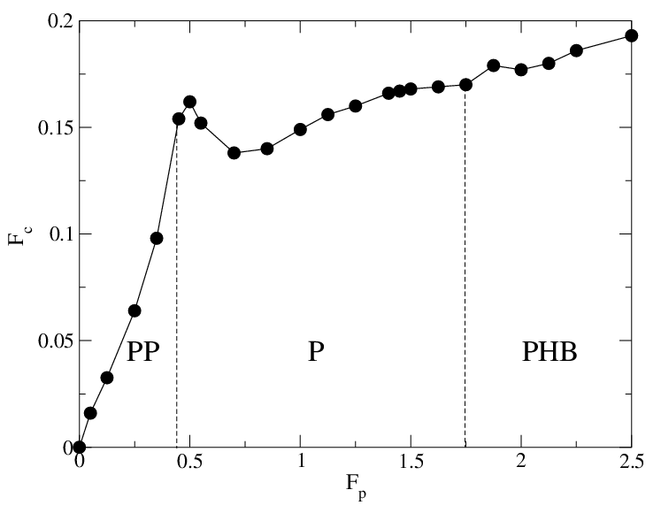
The critical depinning force in the x-direction, Fxc (open squares), and in the y-direction, Fyc (filled circles), vs Fp for B/Bϕ = 2.0, Rp = 0.35λ, and np=0.3125/λ2. PP: partially pinned phase; P: pinned dimer phase; PHB: pinned herringbone phase; J: jammed state. In the PP phase, Fcx=Fcy, while in the P phase, Fcx > Fcy. A large enhancement of Fcy occurs in the PHB phase when dimer jamming occurs. Inset: the ratio Fyc/Fxc vs Fp. The dashed line indicates Fyc/Fxc=1, where the depinning thresholds are equal.
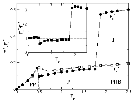
In order to better characterize the enhancement of Fc in the jammed state, in Fig. 29 we plot the critical depinning force in the y-direction, Fyc, and in the x-direction, Fxc, versus FP. In the inset of Fig. 29 we show the ratio Fyc/Fxc versus Fp. In the partially pinned (PP) phase, Fcy=Fcx, while in the pinned aligned dimer (P) phase, Fcx is slightly higher than Fcy since the vortices can depin more readily into the 1DMI phase in the y-direction. In the jammed state that forms from the PHB phase, Fyc is 3.1 times higher than Fxc for the same value of Fp.
Fig30.png
Figure 30: The dynamic phase diagram for FD vs Rp with FD=FDy, B/Bϕ = 2.0, Fp = 0.85, and np=0.3125/λ2. PP: partially pinned phase; J: jammed state; P: pinned phase; MI2Y: y-direction moving interstitial phase 2; 1DMI: one-dimensional moving interstitial phase; R: random phase; ML: moving locked phase. For Rp < 0.2λ the system forms the PP phase. This depins into the MI2Y state for driving in the y-direction, which is similar to the MI2 state shown in Fig. 19(a) for driving in the x-direction. For 0.2λ < Rp < 0.3λ, the system forms the jammed J state shown in Fig. 28.

B.  Effects of Changing Rp and Bϕ

In Fig. 30 we plot the dynamical phase diagram FD versus Rp for driving in the y-direction with B/Bϕ = 2.0, Fp = 0.85, and np=0.3125/λ2. For Rp ≥ 0.2λ, the system depins into the 1DMI phase and makes a transition to the ML phase at higher drives. For Rp < 0.2λ, the system forms the partially pinned (PP) phase where only half of the pinning sites are occupied. The PP phase depins into a moving interstitial phase (MI2Y) that resembles the MI2 state observed for driving in the x-direction in Fig. 19(b), where half the vortices depin while the other half remain pinned. The MI2Y phase is oriented 90° from the MI2 phase. At FD = 0.4 for Rp < 0.2λ, the vortices at the pinning sites begin to depin and repin, giving a regime of the random (R) phase until FD becomes large enough for all the vortices to depin into the ML phase. For 0.2λ ≤ Rp ≤ 0.3λ, the jammed (J) state discussed in Fig. 28 occurs due to the formation of dimers aligned in the x-direction, which is associated with a marked increase in Fc. As discussed earlier, the pinned herringbone (PHB) phase and jammed (J) state occur when Fp becomes high enough that the vortices in the pinning sites cannot shift to allow for dimer ordering to occur. Similarly, as Rp is reduced, the vortices in the pinning sites have less room to adjust for dimer ordering, so the PHB state forms. The jamming also produces the counterintuitive effect that as Rp increases above Rp=0.35λ, the depinning threshold decreases.
Fig31.png
Figure 31: The dynamical phase diagram for FD vs np, which determines Bϕ, for driving in the y-direction with B/Bϕ = 2.0, Rp = 0.85λ, and Fp = 0.85. P: pinned ordered dimer phase; 1DMI: one-dimensional moving interstitial phase; ML: moving locked phase.
In Fig. 31 we show the dynamical phase diagram for FD versus np, which determines the value of Bϕ, for B/Bϕ = 2.0, Rp = 0.35λ, and Fp = 0.85. As np increases, the critical depinning force into the 1DMI phase increases since the repulsion from the pinned vortices experienced by the interstitial vortices increases as the average vortex-vortex spacing decreases. The transition from the 1DMI phase to the ML phase shifts to higher values of FD as np decreases since the distance between the pinning sites which stabilize the ML flow increases.

V.  DISCUSSION

Our results are for honeycomb pinning arrays where it was shown in previous work that n-merization of the interstitial vortices into vortex molecular crystal states occurs for B/Bϕ > 1.5. Many of the dynamical effects presented in this work are due to the n-merization effect. In kagomé pinning arrays, similar types of vortex molecular crystal states appear, so we expect that many of the same types of dynamic phases described here will also occur for kagomé pinning arrays, although we do expect that there will be certain differences as well. In the kagomé pinning array, the vortex dimer state appears at B/Bϕ = 1.5 and has a herringbone ordering even for large, weak pins. There are no easy flow channels along ±30° to the x-axis, so the symmetry breaking flows should be absent. Additionally, since there is no easy flow channel in the y-direction, the anisotropic depinning dynamics may be different as well.
We have only considered B/Bϕ < 2.5 in this work. At higher fields, a wide array of vortex molecular crystal states occur that should also have interesting dynamical phases. Since the low matching fields are more robust, observing the dynamics near these low fields experimentally is more feasible. Although our results are specifically for pinning sites with single vortex occupation, similar dynamics should occur if the first few matching fields have multiple vortices at the pinning sites. In this case, the effective dimerization of the interstitial vortices would be shifted to higher magnetic fields.
Although true phase transitions are associated only with equilibrium phenomena, the nonequilibrium phases considered here have many analogies to equilibrium phases. For example, several of the transitions between the nonequilibrium phases have a continuous type behavior, while in other cases the transitions are sharp, indicative of a first order nature. Future studies could explore the possible emergence of a growing correlation length near the transitions to see whether they exhibit the true power law behavior associated with continuous phase transitions or whether they show crossover behavior. For transitions that exhibit first order characteristics, it would be interesting to prepare a small patch of pinning sites with different characteristics that could act as a nucleation site for one of the phases in order to understand whether there is a length scale analogous to a critical nucleus size.
We also note that the dynamics we observe should be general to systems with similar geometries and repulsively interacting particles. For example, in colloidal systems, square pinning arrays with flat regions between the pinning sites (muffin-tin potentials) have been fabricated, and in these systems the interstitial colloids are much more mobile than in washboard-type pinning potentials. Honeycomb pinning arrays could be created using similar techniques for this type of system.

VI.  SUMMARY

We have shown that vortices in honeycomb pinning arrays exhibit a rich variety of dynamical phases that are distinct from those found in triangular and square pinning arrays. The honeycomb pinning arrays allow for the appearance of n-mer type states that have orientational degrees of freedom. We specifically focused on the case where dimer states appear. At B/Bϕ=2.0, the dimers can have a ferromagnetic type of ordering which is three-fold degenerate. At depinning, the dimers can flow in the direction in which they are aligned. For the case of driving along the x-axis, the dimers flow at ±30° to the applied drive, giving a transverse velocity response. At incommensurate fields where dimers are present, even though the orientational order is lost, the moving states can dynamically order into a broken symmetry state where the vortices flow with equal probability at either +30° or −30° to the x-axis. As the driving in the x-direction increases, there is a depinning transition for the vortices in the pinning sites, and the transverse response is lost when the vortices either flow in a random phase or channel along the pinning sites. As a function of pinning force, we find other types of vortex lattice ordering at zero driving, including a partially pinned lattice and a herringbone ordering of the dimers. These other orderings lead to new types of dynamical phases, including an elastic depinning for weak pinning where all the vortices depin simultaneously into a moving crystal phase, and an ordered interstitial flow in which the moving dimers break apart. The transitions between these flow phases appear as clear steps in the velocity force curves, and we have mapped the dynamical phase diagrams for various system parameters. We also showed that the different phases have distinct fluctuations and noise characteristics. When the temperature is high enough, the dimer states lose their orientational ordering and begin to rotate within the interstitial sites. This destroys the symmetry breaking flow; however, the moving locked phase can still occur at high drives.
The transition in the vortex ground state ordering as a function of pinning force causes the critical depinning force for driving in the x and y-directions to differ. When driving along the y-direction, the initial depinning occurs in the form of one-dimensional interstitial channels, and at high drives the vortices can form an anisotropic moving locked phase. We find a large enhancement of the depinning force in the y-direction associated with the pinned herringbone phase when the dimers align in the x-direction and creates a jamming effect. The jammed state can enhance the critical depinning force by a factor of three, and can also arise for decreasing pinning size. We expect that many of the general features we observe will carry over to the higher matching fields in the honeycomb pinning arrays and in kagomé arrays since ordered n-mers states occur for the kagomé lattice as well.

  ACKNOWLEDGMENTS

This work was carried out under the auspices of the National Nuclear Security Administration of the U.S. Department of Energy at Los Alamos National Laboratory under Contract No. DE-AC52-06NA25396.

References

[1]
E.H. Brandt, Phys. Rev. Lett. 50, 1599 (1983); E.H. Brandt, J. Low. Temp. Phys. 53, 41 (1983); 53, 71 (1983).
[2]
H.J. Jensen, A. Brass, and A.J. Berlinsky, Phys. Rev. Lett. 60, 1676 (1988); M.C. Faleski, M.C. Marchetti, and A.A. Middleton, Phys. Rev. B 54, 12427 (1996); C.J. Olson, C. Reichhardt, and F. Nori, Phys. Rev. Lett. 80, 2197 (1998); K.E. Bassler, M. Paczuski, and E. Altshuler, Phys. Rev. B 64, 224517 (2001); E. Olive and J.C. Soret, ibid. 77, 144514 (2008).
[3]
A.E. Koshelev and V.M. Vinokur, Phys. Rev. Lett. 73, 3580 (1994).
[4]
S. Bhattacharya and M.J. Higgins, Phys. Rev. Lett. 70, 2617 (1993).
[5]
P. Le Doussal and T. Giamarchi, Phys. Rev. B 57, 11356 (1998).
[6]
L. Balents, M.C. Marchetti, and L. Radzihovsky, Phys. Rev. Lett. 78, 751 (1997); Phys. Rev. B 57, 7705 (1998).
[7]
K. Moon, R.T. Scalettar, and G.T. Zimányi, Phys. Rev. Lett. 77, 2778 (1996); S. Spencer and H.J. Jensen, Phys. Rev. B 55, 8473 (1997); C.J. Olson, C. Reichhardt, and F. Nori, Phys. Rev. Lett. 81, 3757 (1998); A.B. Kolton, D. Domínguez, and N. Grønbech-Jensen, ibid. 83, 3061 (1999); H. Fangohr, S.J. Cox, and P.A.J. de Groot, Phys. Rev. B 64, 064505 (2001).
[8]
F. Pardo, F. de la Cruz, P.L. Gammel, E. Bucher, and D.J. Bishop, Nature (London) 396, 348 (1998).
[9]
A.M. Troyanovski, J. Aarts, and P.H. Kes, Nature (London) 399, 665 (1999).
[10]
Q.-H. Chen and X. Hu, Phys. Rev. Lett. 90, 117005 (2003); A.K. Ghosh, P. Olsson, and S. Teitel, ibid. 97, 267002 (2006).
[11]
A.C. Marley, M.J. Higgins, and S. Bhattacharya, Phys. Rev. Lett. 74, 3029 (1995).
[12]
Y. Togawa, R. Abiru, K. Iwaya, H. Kitano and A. Maeda, Phys. Rev. Lett. 85, 3716 (2000); S. Okuma, J. Inoue, and N. Kokubo, Phys. Rev. B 76, 172503 (2007).
[13]
A.T. Fiory, A.F. Hebard, and S. Somekh, Appl. Phys. Lett. 32, 73 (1978).
[14]
V.V. Metlushko, M. Baert, R. Jonckheere, V.V. Moshchalkov, and Y. Bruynseraede, Sol. St. Commun. 91, 331 (1994).
[15]
M. Baert, V.V. Metlushko, R. Jonckheere, V.V. Moshchalkov, and Y. Bruynseraede, Phys. Rev. Lett. 74, 3269 (1995).
[16]
K. Harada, O. Kamimura, H. Kasai, T. Matsuda, A. Tonomura, and V.V. Moshchalkov, Science 274, 1167 (1996).
[17]
E. Rosseel, M. Van Bael, M. Baert, R. Jonckheere, V.V. Moshchalkov, and Y. Bruynseraede, Phys. Rev. B 53, R2983 (1996).
[18]
L. Van Look, E. Rosseel, M.J. Van Bael, K. Temst, V.V. Moshchalkov, and Y. Bruynseraede, Phys. Rev. B 60, R6998 (1999).
[19]
V.V. Metlushko, L.E. DeLong, M. Baert, E. Rosseel, M.J. Van Bael, K. Temst, V.V. Moshchalkov, and Y. Bruynseraede, Europhys. Lett. 41, 333 (1998).
[20]
V. Metlushko, U. Welp, G.W. Crabtree, R. Osgood, S.D. Bader, L.E. DeLong, Z. Zhang, S.R.J. Brueck, B. Ilic, K. Chung, and P.J. Hesketh, Phys. Rev. B 60, R12585 (1999).
[21]
S.B. Field, S.S. James, J. Barentine, V. Metlushko, G. Crabtree, H. Shtrikman, B. Ilic, and S.R.J. Brueck, Phys. Rev. Lett. 88, 067003 (2002); A.N. Grigorenko, S.J. Bending, M.J. Van Bael, M. Lange, V.V. Moshchalkov, H. Fangohr, and P.A.J. de Groot, ibid. 90, 237001 (2003).
[22]
J.I. Martín, M. Vélez, J. Nogués, and I.K. Schuller, Phys. Rev. Lett. 79, 1929 (1997).
[23]
U. Welp, Z.L. Xiao, J.S. Jiang, V.K. Vlasko-Vlasov, S.D. Bader, G.W. Crabtree, J. Liang, H. Chik, and J.M. Xu, Phys. Rev. B 66, 212507 (2002).
[24]
J.I. Martín, M. Vélez, A. Hoffmann, I.K. Schuller, and J.L. Vicent, Phys. Rev. Lett. 83, 1022 (1999).
[25]
G. Karapetrov, J. Fedor, M. Iavarone, D. Rosenmann, and W.K. Kwok, Phys. Rev. Lett. 95, 167002 (2005).
[26]
D.J. Morgan and J.B. Ketterson, Phys. Rev. Lett. 80, 3614 (1998).
[27]
T.C. Wu, J.C. Wang, L. Horng, J.C. Wu, and T.J. Yang, J. Appl. Phys. 97, 10B102 (2005).
[28]
V.R. Misko, S. Savel'ev, and F. Nori, Phys. Rev. Lett. 95, 177007 (2005); Phys. Rev. B 74, 024522 (2006); M. Kemmler, C. Gürlich, A. Sterck, H. Pöhler, M. Neuhaus, M. Siegel, R. Kleiner, and D. Koelle, Phys. Rev. Lett. 97, 147003 (2006); A.V. Silhanek, W. Gillijns, V.V. Moshchalkov, B.Y. Zhu, J. Moonens, and L.H.A. Leunissen, Appl. Phys. Lett. 89, 152507 (2006).
[29]
J.E. Villegas, M.I. Montero, C.-P. Li, and I.K. Schuller, Phys. Rev. Lett. 97, 027002 (2006); J. Eisenmenger, M. Oettinger, C. Pfahler, A. Plettl, P. Walther, and P. Ziemann, Phys. Rev. B 75, 144514 (2007); C. Reichhardt and C.J. Olson Reichhardt, ibid. 76, 094512 (2007).
[30]
C. Reichhardt, C.J. Olson, and F. Nori, Phys. Rev. B 57, 7937 (1998).
[31]
C.J. Olson Reichhardt, A. Libál, and C. Reichhardt, Phys. Rev. B 73, 184519 (2006).
[32]
G.R. Berdiyorov, M.V. Milosevic, and F.M. Peeters, Phys. Rev. B 74, 174512 (2006).
[33]
W.V. Pogosov, A.L. Rakhmanov, and V.V. Moshchalkov, Phys. Rev. B 67, 014532 (2003); G.R. Berdiyorov, M.V. Milosevic, and F.M. Peeters, ibid. 76, 134508 (2007).
[34]
C. Reichhardt, C.J. Olson, and F. Nori, Phys. Rev. Lett. 78, 2648 (1997); Phys. Rev. B 58, 6534 (1998).
[35]
C. Reichhardt and N. Grønbech-Jensen, Phys. Rev. B 63, 054510 (2001).
[36]
C. Reichhardt, G.T. Zimányi, and N. Grønbech-Jensen, Phys. Rev. B 64, 014501 (2001).
[37]
C. Reichhardt, R.T. Scalettar, G.T. Zimányi, and N. Grønbech-Jensen, Phys. Rev. B 61, R11914 (2000).
[38]
C. Reichhardt, A.B. Kolton, D. Domínguez, and N. Grønbech-Jensen, Phys. Rev. B 64, 134508 (2001); V.I. Marconi, A.B. Kolton, D. Domínguez, and N. Grønbech-Jensen, ibid. 68, 104521 (2003).
[39]
G. Carneiro, Phys. Rev. B 66, 054523 (2002).
[40]
B.Y. Zhu, L. Van Look, V.V. Moshchalkov, B.R. Zhao, and Z.X Zhao, Phys. Rev. B 64, 012504 (2001).
[41]
L. Van Look, B.Y.Zhu, R. Jonckheere, B.R. Zhao, Z.X. Zhao, and V.V. Moshchalkov, Phys. Rev. B 66, 214511 (2002).
[42]
M. Benkraouda, I.M. Obaidat, U. Al Khawaja, and N.M.J. Mulaa, Supercond. Sci. Technol. 19, 368 (2006).
[43]
Q.H. Chen, G. Teniers, B.B. Jin, and V.V. Moshchalkov, Phys. Rev. B 73, 014506 (2006).
[44]
V.R. Misko, S. Savel'ev, A.L. Rakhmanov, and F. Nori, Phys. Rev. Lett. 96, 127004 (2006); Phys. Rev. B 75, 024509 (2007).
[45]
T.C. Wu, P.C. Kang, L. Horng, J.C. Wu, and T.J. Yang, J. Appl. Phys. 95, 6696 (2004).
[46]
R. Cao, T.C. Wu, P.C. Kang, J.C. Yang, T.J. Yang, and L. Horng, Sol. St. Commun. 143, 171 (2007).
[47]
K.D. Fisher, D. Stroud, and L. Janin, Phys. Rev. B 60, 15371 (1999); V.I. Marconi and D. Domínguez, Phys. Rev. Lett. 82, 4922 (1999).
[48]
C. Reichhardt and G.T. Zimányi, Phys. Rev. B 61, 14354 (2000); V. Gotcheva, A.T.J. Wang, and S. Teitel, Phys. Rev. Lett. 92, 247005 (2004).
[49]
R. Surdeanu, R.J. Wijngaarden, R. Griessen, J. Einfeld, and R. Wördenweber, Europhys. Lett. 54, 682 (2001).
[50]
C.C. de Souza Silva, J. Van de Vondel, B.Y. Zhu, M. Morelle, and V.V. Moshchalkov, Phys. Rev. B 73, 014507 (2006); Q. Lu, C.J. Olson Reichhardt, and C. Reichhardt, ibid. 75, 054502 (2007); L. Dinis, E.M. Gonzalez, J.V. Anguita, J.M.R. Parrondo, and J.L. Vicent, New. J. Phys. 9, 366 (2007).
[51]
C. Reichhardt and C.J. Olson Reichhardt, Phys. Rev. B 76, 064523 (2007).
[52]
C. Reichhardt and C.J. Olson, Phys. Rev. Lett. 88, 248301 (2002).
[53]
M. Brunner and C. Bechinger, Phys. Rev. Lett. 88, 248302 (2002).
[54]
R. Agra, F. van Wijland, and E. Trizac, Phys. Rev. Lett. 93, 018304 (2004).
[55]
A. Sarlah, T. Franosch, and E. Frey, Phys. Rev. Lett. 95, 088302 (2005).
[56]
S. El Shawish, J. Dobnikar, and E. Trizac, Soft Matter 4, 1491 (2008).
[57]
A.B. Harris and A.J. Berlinsky, Can. J. Phys. 57, 1852 (1979); E.J. Nicol, C. Kallin, and A.J. Berlinsky, Phys. Rev. B 38, 556 (1988); P. Zeppenfeld, J. Goerge, V. Diercks, R. Halmer, R. David, G. Comsa, A. Marmier, C. Ramseyer, and C. Girardet, Phys. Rev. Lett. 78, 1504 (1997).
[58]
M.F. Laguna, C.A. Balseiro, D. Domínguez, and F. Nori, Phys. Rev. B 64, 104505 (2001).
[59]
C. Reichhardt and C.J. Olson Reichhardt, Phys. Rev. Lett. 100, 167002 (2008).
[60]
H. Pu, L.O. Baksmaty, S. Yi, and N.P. Bigelow, Phys. Rev. Lett. 94, 190401 (2005); J.W. Reijnders and R.A. Duine, Phys. Rev. A 71, 063607 (2005).
[61]
S. Tung, V. Schweikhard, and E.A. Cornell, Phys. Rev. Lett. 97, 240402 (2006).
[62]
K. Kasamatsu and M. Tsubota, Phys. Rev. Lett. 97, 240404 (2006).
[63]
P.T. Korda, G. C. Spalding, and D.G. Grier, Phys. Rev. B 66, 024504 (2002); K. Mangold, P. Leiderer, and C. Bechinger, Phys. Rev. Lett. 90, 158302 (2003).
[64]
G. Coupier, M. Saint Jean, and C. Guthmann, Phys. Rev. B 75, 224103 (2007).
[65]
O.M. Braun, T. Dauxois, M.V. Paliy, and M. Peyrard, Phys. Rev. Lett. 78, 1295 (1997); E. Granato and S.C. Ying, Phys. Rev. B 69, 125403 (2004); J. Tekic, O.M. Braun, and B. Hu, Phys. Rev. E 71, 026104 (2005).
[66]
C.J. Olson Reichhardt and C. Reichhardt, Physica C 432, 125 (2005).
[67]
S. Savel'ev, V.R. Misko, F. Marchesoni, and F. Nori, Phys. Rev. B 71, 214303 (2005).
[68]
A.B. Kolton, Phys. Rev. B 75, 020201 (2007).
[69]
E.M. Gonzalez, N.O. Nunez, J.V. Anguita, and J.L. Vicent, Appl. Phys. Lett. 91, 062505 (2007); A.V. Silhanek, J. Van de Vondel, V.V. Moshchalkov, A. Leo, V. Metlushko, B. Ilic, V.R. Misko, and F.M. Peeters, ibid. 92, 176101 (2008); E.M. Gonzalez, N.O. Nunez, J.V. Anguita, and J.L. Vicent, ibid. 92, 176102 (2008).


File translated from TEX by TTHgold, version 4.00.

Back to Home