Physical Review B 93, 064508 (2016)

Transverse ac-Driven and Geometric Ratchet Effects for Vortices in Conformal Crystal Pinning Arrays

C. Reichhardt and C. J. Olson Reichhardt

Theoretical Division, Los Alamos National Laboratory, Los Alamos, New Mexico 87545 USA

(Received 4 December 2015; published 11 February 2016)

A conformal pinning array is created by taking a conformal transformation of a uniform hexagonal lattice to create a new structure in which the six-fold ordering of the original lattice is preserved but which has a spatial gradient in the pinning site density. With a series of conformal arrays it is possible to create asymmetric substrates, and it was previously shown that when an ac drive is applied parallel to the asymmetry direction, a pronounced ratchet effect occurs with a net dc flow of vortices in the same direction as the ac drive. Here we show that when the ac drive is applied perpendicular to the substrate asymmetry direction, it is possible to realize a transverse ratchet effect where a net dc flow of vortices is generated perpendicular to the ac drive. The conformal transverse ratchet effect is distinct from previous versions of transverse ratchets in that it occurs due to the generation of non-Gaussian transverse vortex velocity fluctuations by the plastic motion of vortices, so that the system behaves as a noise correlation ratchet. The transverse ratchet effect is much more pronounced in the conformal arrays than in random gradient arrays, and is absent in square gradient arrays due the different nature of the vortex flow in each geometry. We show that a series of reversals can occur in the transverse ratchet effect due to changes in the vortex flow across the pinning gradient as a function of vortex filling, pinning strength, and ac amplitude. We also consider the case where a dc drive applied perpendicular to the substrate asymmetry direction generates a net flow of vortices perpendicular to the dc drive, producing what is known as a geometric or drift ratchet that again arises due to non-Gaussian dynamically generated fluctuations. The drift ratchet is more efficient than the ac driven ratchet and also exhibits a series of reversals for varied parameters. Our results should be general to a wide class of systems undergoing nonequilibrium dynamics on conformal substrates, such as colloidal particles on optical traps.
I. INTRODUCTION
II. SIMULATION AND SYSTEM
III. TRANSVERSE AC RATCHET EFFECT
A. Transverse ratchet reversals
B. Thermal fluctuations
C. Comparison to longitudinal gradient ratchets
IV. DRIFT RATCHET
A. Drift ratchet reversals
B. Transverse velocity fluctuations
V. RATCHET EFFECTS FOR COLLOIDAL PARTICLES
VI. SUMMARY
References

I.  INTRODUCTION

When a particle interacts with an asymmetric substrate under an ac drive, it is possible to realize a ratchet effect in which a net dc motion of the particle can occur. If the ac drive is in the form of a periodic external force, the system is characterized as a rocking ratchet, while if the particles are undergoing thermal agitation and the substrate is periodically flashed on and off, the system is known as a flashing ratchet [1,2]. It is also possible to generate dc motion of a particle in an asymmetric substrate in the absence of periodic driving when the noise fluctuations experienced by the particle are not white but have an additional time correlation. Such systems are known as correlation ratchets [3,4,5,6]. Another type of ratchet system, the geometric or drift ratchet, arises when dc driven particles move through an assembly of asymmetric obstacles. The interactions of the particles with the obstacles produces an additional drift of particles in the direction perpendicular to the dc drive [7,8,9,10,11]. One system in which a remarkably rich variety of rocking ratchet effects has been realized is vortices in type-II superconductors interacting with some form of asymmetric substrate where an ac driving force is applied along the direction of the substrate asymmetry [12,13,14,15,16,17,18,19,20,21,22,23,24]. Such asymmetric pinning arrays include periodic one-dimensional (1D) asymmetric saw-tooth thickness modulations [12,19,23,25,26], channels with funnel shapes [13,20,21,27,28], and arrays of pinning sites in which the individual pinning sites have an intrinsic asymmetry [15,17,18,22,24,29,30]. In the case where the vortex-vortex interactions are weak, such as at low magnetic fields, the net dc flow is in the easy direction of the substrate asymmetry, but when collective vortex interactions come into play it is possible to observe reversals of the ratchet effect in which the net dc vortex motion switches to follow the hard direction of the substrate asymmetry, and there may be multiple ratchet reversals as a function of vortex density and ac driving amplitudes [15,18,19,25,26,31,32,33,34,35]. It is also possible to create transverse vortex ratchets where a net dc flow of vortices occurs that is perpendicular to the applied ac driving force [36,37,38,39,40]. Such transverse ratchets have been realized for vortices interacting with arrays of triangular pins or other pinning site shapes that have an intrinsic asymmetry. When vortices interact with such pinning sites, they are partially deflected in the direction perpendicular to the ac force [39,40].
Vortex ratchet pinning geometries can be created using individual pinning sites that are symmetric by introducing a periodic spatial gradient in the pinning site density [14,41,42,43] or a gradient in the size of the pinning sites [44], and then applying an ac driving force along the direction of the gradient. Gradient ratchets have been studied for randomly arranged pinning with a spatial gradient [41] and periodically arranged pinning arrays with gradients [41,42,43,44]. A new type of pinning geometry called a conformal crystal was recently proposed [45]. It is constructed by applying a conformal transformation to a uniform hexagonal array, resulting in a structure where each pinning site has six neighbors but there is a spatial gradient in the pinning site density [46,47]. Simulations indicate that the pinning effectiveness for a fixed number of pinning sites is maximized for the conformal arrays compared to uniform random arrays or a random arrangement of pinning sites with a gradient [45]. The conformal array also produces more effective pinning than uniform periodic pinning arrays except for fields at or very near integer matching fields. This optimal pinning by conformal arrays was subsequently confirmed in experiments [48,49]. Other studies have also shown that non-conformal gradient pinning arrays produce enhanced pinning compared to uniform arrays [50,51]. Simulations demonstrate that the hexagonal conformal arrays exhibit stronger pinning than arrays constructed by conformally transforming square or quasiperiodic arrays, while square pinning arrays containing 1D spatial density gradients have enhanced pinning compared to the hexagonal conformal arrays at certain magnetic field fillings due to commensuration effects [52].
Vortices interacting with a series of conformal pinning arrays can exhibit a ratchet effect when an external ac drive is applied along the substrate asymmetry direction, and multiple reversals in the ratchet effect can occur as a function of vortex density, pinning force, and drive amplitude due to changes in the vortex flow patterns, as shown in Ref. [53]. In general, the ratchet effect is most pronounced for the conformal pinning arrays compared to random gradient or square gradient pinning arrays; however, at low magnetic fields the ratchet effect is strongest for the square gradient array due to a 1D channeling of vortices along the symmetry direction of the square array.
For conformal or other gradient pinning arrays, it has not been considered whether a transverse ratchet effect could occur when the ac drive is applied perpendicular to the substrate asymmetry direction. Since the individual pinning sites are symmetric in these arrays, it might be expected that transverse ratchet effects would not occur. Here we show that a pronounced transverse vortex ratchet effect appears in conformal pinning arrays, and that the mechanism responsible for this effect differs from that which produces the transverse ratchet effects found for asymmetrically shaped pins or obstacles. For the conformal array, the transverse ratchet effect results when plastic vortex motion generates strong non-Gaussian velocity fluctuations both parallel and perpendicular to the ac driving direction. Due to the pinning gradient, the fluctuations can be stronger in the low pinning density portions of the sample, creating an effective gradient in the size of the fluctuations and producing a dynamical thermophoresis phenomenon. The effect can also be viewed as a realization of a noise correlation ratchet. Noise correlation ratchets were first proposed by Magnasco [3] and Doering et al. [4], who introduced different types of noise correlations directly into the fluctuating noise term governing the equation of motion of a particle placed on an asymmetric substrate. In the conformal pinning array system that we consider, there is no added stochastic noise term in the vortex equation of motion, so the correlated velocity fluctuations are dynamically generated by the plastic motion of the vortices. The onset of plastic flow in vortex systems has been demonstrated both in experiments [54] and simulations to generate strong non-Gaussian vortex velocity fluctuations both parallel and perpendicular to the external driving direction [55,56]. We find that transverse ratchet effects do not occur in square gradient arrays since the vortex trajectories are nearly one-dimensional in the direction parallel to the ac drive, so the transverse fluctuations are too weak to induce transverse ratchet motion. We show that it is possible to realize geometric or drift ratchet effects in the conformal and random gradient arrays when a dc drive is applied perpendicular to the asymmetry direction and a net vortex drift arises that is perpendicular to the dc drive. Geometrical ratchets have been studied for the dc flow of particles through periodic arrays of asymmetric objects, and can arise even in the limit of a single particle [7,8,9,10,11]. In our system the pinning sites are symmetric but a geometric ratchet effect occurs due to the dynamically generated fluctuations from the plastic flow of vortices. In the single particle limit where collective plastic flow is lost, the transverse or geometric ratchet effect is also absent. The geometric ratchet we study has similarities to the geometric ratchet effect proposed by Kolton [57] for particles in a two-dimensional (2D) system moving over a periodic 1D asymmetric substrate containing additional random pinning sites that create nonequilibrium fluctuations, which result in a drift of particles perpendicular to the dc drive direction. We also find that there can be a series of reversals in both the ac and dc driven transverse ratchet effects which is unique among transverse and drift ratchet systems that have been previously studied. Finally, our results should be general to a variety of of other systems which can be described as an assembly of interacting particles moving over a conformal pinning array, such as colloids on optical trap arrays [58].

II.  SIMULATION AND SYSTEM

We consider a 2D simulation geometry with periodic boundary conditions in the x and y-directions. Within the system we place Nv vortices, where the number of vortices is proportional to the applied magnetic field B which is aligned in the z direction. We introduce Np pinning sites to the sample, and denote the field at which the number of vortices equals the number of pinning sites as Bϕ. The dynamics of an individual vortex i is governed by the following overdamped equation of motion:
η d Ri

dt
= Fvvi + Fvpi + Faci + Fdci + FTi.
(1)
Here η is the damping constant which is set equal to 1. The first term on the right is the repulsive vortex-vortex interaction force Fvvi = ∑jiNvF0K1(Rij/λ)Rij, where Ri is the location of vortex i, K1 is the modified Bessel function, λ is the penetration depth, Rij = |RiRj|, Rij = (RiRj)/Rij, F0 = ϕ20/(2πμ0λ3), ϕ0 is the flux quantum, and μ0 is the permittivity. The initial vortex positions before application of an external driving force are obtained by performing simulated annealing from a high temperature state down to T = 0. The vortex-pinning interaction term Fvpi = ∑Npk=1(FpR(p)ik/rp)Θ((rpR(p)ik)/λ)R(p)ik, where Θ is the Heaviside step function, rp = 0.25λ is the pinning radius, Fp is the pinning strength, Rk(p) is the location of pinning site k, Rik(p) = |RiRk(p)|, and Rik(p) = (RiRk(p))/Rik(p). All forces are measured in units of F0 and lengths in units of λ.
Fig1.png
Figure 1: Circles: the pinning site locations for each geometry. The substrate asymmetry direction is always along the x axis. Blue arrow indicates the direction of the ratchet velocity Vx. (a) Three conformal crystal pinning arrays (ConfG). (b) Randomly placed pinning sites with a repeating 1D spatial gradient (RandG). (c) A square pinning array with a series of 1D spatial gradients (SquareG). We consider either ac driving along the y direction (dark green arrow) or dc driving along the positive y direction, and measure Xnet, the net displacement per vortex in the x-direction, to quantify the transverse ratchet and geometric ratchet effects.
Figure 1(a) shows the pinning geometry with three conformal crystals, each of width ap = 12λ, placed sequentially along the x direction of the sample. We refer to this geometry as "ConfG." Each conformal array is generated by performing a conformal transformation of a uniform triangular lattice in the complex z plane, z = n1b + n2exp(iπ/3) b, where n1 and n2 are integers and b is the lattice constant. The transformation that maps the points from the original lattice to the w plane is
w = π


+ 1

iα
ln(iαz)
(2)
where α is a parameter. This transformation maps a semi-annular section covering the region rin ≤ |z| ≤ rout of the original lattice to a rectangular region. We use α = π/36, an outer annulus radius of rout=1/α, an inner annulus radius of rin = (1/α)exp(−π/3), and set the lattice constant to b = √{(1 − exp(−2π/3)(√3/π)}. As shown in Fig. 1(a) the easy flow direction is along the negative x direction. We also consider a system with a spatial density gradient of randomly placed pinning sites, shown in Fig. 1(b) and referred to as "RandG," as well as a non-conformal gradient array constructed by introducing a one-dimensional density gradient to a regular square lattice, illustrated in Fig. 1(c) and referred to as "SquareG."
In previous work examining longitudinal ratchet effects, both the applied ac drive and the measured net motion were along the x-direction or parallel to the substrate asymmetry direction [53]. In the present work we apply the ac driving along the y-direction or perpendicular to the substrate symmetry direction, as indicated in Fig. 1, but still measure the net flow of vortices along the x direction, such that a finite dc flow signature indicates the existence of a transverse ratchet effect. The ac driving term is Faci = Fyacsin(ωt)y, where Fyac is the ac amplitude. To measure the ratchet effect we sum the vortex displacements perpendicular to the ac drive, Xnet = N−1vNvi=1(xi(t) − xi(t0)), where xi(t) is the x position of vortex i at time t and xi(t0) is the initial position of the vortex when the ac drive is first applied. We also measure the corresponding Ynet using the net displacements along the y direction, and find that, due to the lack of substrate asymmetry along the y direction, Ynet=0 for all ac drives that we consider. We focus on the case with a fixed ac period of 8000 simulation time steps unless otherwise noted, and allow the system to run for 50 ac cycles before beginning the measurement of Xnet to avoid any transient effects, as was done in previous studies of longitudinal ratchet effects [53]. We also consider the case Fyac = 0 in which we apply a finite dc force Fdci = Fydcy along the positive y-direction, and examine Xnet after the equivalent of 50 ac cycles of time has passed to quantify the geometric ratchet effect. Finally, we consider the effect of adding thermal fluctuations using FTi, which has the properties 〈FTi(t)〉 = 0 and 〈FTi(t)FTj(t)〉 = 2ηkBTδijδ(tt), where kB is the Boltzmann constant. Unless otherwise noted, we set FT=0.

III.  TRANSVERSE AC RATCHET EFFECT

Fig2.png
Figure 2: Xnet, the average displacement per vortex in the longitudinal x-direction, vs ac cycle number for an ac drive Fyac applied in the transverse or y direction in samples with B/Bϕ=1.0 and Fp=1.0. (a) The ConfG conformal array in Fig. 1(a) at Fyac = 0.6 (upper light blue curve) where there is no ratchet effect, at Fyac = 0.8 (lower dark blue cuve) where there is a strong ratchet effect, and Fyac = 1.6 (middle green curve) where there is a finite but reduced ratchet effect. (b) At Fyac=0.8, the SquareG square gradient array from Fig. 1(c) (upper red curve) has no ratchet effect, the RandG random gradient array from Fig. 1(b) (middle brown curve) has a weak ratchet effect, and the ConfG array (lower dark blue curve) has a strong ratchet effect. The conformal array generates a ratchet effect that is approximately 20 times more effective than that of the RandG array. In all cases Ynet = 0.0.
In Fig. 2(a) we plot Xnet, the net displacement per vortex in the x-direction, verus time in ac drive cycles for the ConfG conformal array in Fig. 1(a) at B/Bϕ = 1.0 and Fp = 1.0. For Fyac = 0.6, Xnet = 0 indicating that there is no transverse ratchet effect. At Fyac = 0.8 a finite transverse ratchet effect emerges and the vortices each move an average of 12.5λ in the negative x direction during 50 ac drive cycles. The vortices translate along the easy flow direction of the substrate, and the displacement increases linearly with time indicating that transient effects are not present. For Fyac = 1.6, ratcheting still occurs but the effect is reduced, with the vortices moving an average of 5.0λ in the negative x direction during 50 ac drive cycles.
Fig3.png
Figure 3: (a) Xnet after 50 ac drive cycles versus Fyac for samples with B/Bϕ = 1.0 and Fp = 1.0. Red squares: SquareG array; brown circles: RandG array; dark blue triangles: ConfG array. The ConfG array produces the strongest ratchet effect, while the ratchet effect is absent in the SquareG array. (b) Xnet after 50 ac drive cycles vs Fyac for a ConfG array with Fp = 1.0 at B/Bϕ = 1.0 (dark blue up triangles), 0.5 (light blue left triangles), 0.2 (green down triangles), 0.1 (orange right triangles), and 0.05 (red diamonds), showing that collective effects are important for the transverse ratchet motion.
Figure 2(b) shows Xnet at B/Bϕ=1.0, Fp=1.0, and Fyac = 0.8 for the different array types. In the SquareG square gradient array from Fig. 1(c), Xnet = 0 after 50 ac cycles, while the RandG random gradient array from Fig. 1(b) exhibits ratcheting that is 20 times less effective than in the ConfG array, which is also shown for comparison. To better quantify the ratchet as a function of Fyac, in Fig. 3(a) we plot the value of Xnet at the end of 50 ac drive cycles for ConfG, RandG, and SquareG arrays at Fp = 1.0 and B/Bϕ = 1.0. In the ConfG array, Xnet = 0.0 when Fyac < 0.6, and the ratchet reaches its maximum efficiency near Fyac = 0.8, after which Xnet gradually approaches zero with increasing Fyac. The RandG array shows similar behavior, but has a much weaker overall ratchet effect and exhibits an efficiency maximum at Fyac = 1.2. In the SquareG array, Xnet = 0 for all values of Fyac.
To explore the role of vortex-vortex interactions in the ratchet effect, in Fig. 3(b) we plot the value of Xnet after 50 ac drive cycles versus Fyac for the ConfG system in Fig. 3(a) at B/Bϕ = 1.0, 0.5, 0.2, 0.1, and 0.05. The overall effectiveness of the ratchet decreases with decreasing B/Bϕ, and for B/Bϕ < 0.1 the ratchet effect is absent. Whenever Fyac > Fp, there is a portion of the ac cycle during which all of the vortices are depinned and moving, so the loss of the ratchet effect at low B/Bϕ is not caused by the vortices becoming pinned when their density is small. Instead, this result indicates that collective vortex-vortex interactions are important for the transverse ratchet to occur.
Fig4.png
Figure 4: The pinning site locations (open circles), instantaneous vortex positions (red dots), and vortex trajectories (lines) for samples with B/Bϕ = 1.0 and Fp = 1.0. (a) In the ConfG array at Fyac = 0.5 there is no ratchet effect. (b) The ConfG array at Fyac = 0.8 shows a ratchet effect. (c) There is no ratchet effect in the SquareG array at Fyac=0.5. (d) There is also no ratchet effect in the SquareG array at Fyac=0.8. The vortex motion is more one-dimensional along the y-direction in the SquareG array than in the ConfG array.
In Fig. 4(a) we plot the instantaneous vortex positions, vortex trajectories, and pinning site locations for the ConfG array in Fig. 3(a) at Fyac = 0.5 where there is no ratcheting. Here the vortex motion is confined to the low pinning density regions of the sample. For lower values of Fyac, the width of the regions of moving vortices decreases. For Fyac > 0.6, all the vortices are able to move, as shown in Fig. 4(b) for Fyac = 0.8 where finite ratcheting in the negative x-direction occurs. The vortices do not move strictly along the y or driving direction, but follow winding trajectories that introduce strong x-direction velocity fluctuations. In a SquareG array with the same parameters, no ratcheting occurs. Figure 4(c) shows that at Fyac = 0.5 in the SquareG array, the vortex trajectories are strongly one-dimensional and are oriented along the y direction with few or no fluctuations along the x direction. In Fig. 4(d), at Fyac = 0.8 for the SquareG array all the vortices can participate in the flow during some portion of the ac cycle, but again the motion follows nearly straight trajectories along the y-direction and there is no ratchet effect. As Fyac increases above Facy=0.8, the x direction meandering of the vortex trajectories in the ConfG array is progressively reduced, and this coincides with the drop in ratchet efficiency shown in Fig. 3(a). The vortex trajectories for the RandG array are similar in appearance to those shown for the ConfG array.
Fig5.png
Figure 5: P(Vx), the distribution of individual vortex velocities obtained over 50 ac driving cycles, for the system in Fig. 3 at B/Bϕ = 1.0 and Fp = 1.0. The solid light blue line is a plot of a Gaussian curve with P(Vx)=V0exp(−αx2). (a) The ConfG array at Fyac = 0.5 (red diamonds) where there is no ratchet effect, Fyac=0.8 (dark blue up triangles) where there is a strong ratchet effect, and Fyac=3.5 (orange down triangles) where there is a weak ratchet effect. (b) P(Vx) at Fyac = 0.8 for the SquareG array (red squares) where there is no ratchet effect, the ConfG array (dark blue triangles) where there is a strong ratchet effect, and the RandG array (brown circles) where there is a weak ratchet effect. The fluctuations for the RandG array are nearly Gaussian.
The transverse ratchet in the ConfG and RandG arrays can be understood as a realization of a noise correlation ratchet where the correlated noise is generated by the plastic flow of the vortices. To clarify this, we examine the x-component velocity distributions P(Vx) of the individual vortices over a fixed time of 50 ac drive cycles. In Fig. 5(a) we plot P(Vx) for the ConfG system from Fig. 3 with B/Bϕ = 1.0 and Fp = 1.0. At Fyac = 0.8, where there is a strong ratchet effect, P(Vx) differs significantly from the simple Gaussian form P(Vx)=V0exp−αx2, which is plotted as a smooth solid line. For Fyac = 0.5 where there is no ratcheting, there is a strong peak in P(Vx) at Vx = 0 due to the pinned vortices, and the magnitude of the x velocity fluctuations are significantly reduced compared to the Fyac = 0.8 case. For Fyac = 3.5 where the ratchet effect is present but weak, as shown in Fig. 3(a), the width of P(Vx) is smaller than at the optimal ac drive of Fyac=0.8.
In Fig. 5(b) we plot P(Vx) for the ConfG, SquareG, and RandG arrays from Fig. 3(a) at Fyac = 0.8. The width of P(Vx) is much narrower for the SquareG array than for the ConfG and RandG arrays due to the strongly 1D nature of the vortex trajectories in the SquareG array, as shown in Fig. 4(d). In the RandG array, P(Vx) for Vx < −0.01 is nearly identical to that of the ConfG array; however, close to Vx=0 the RandG array lacks the pinned vortex peak found in the ConfG array and instead maintains a Gaussian form of P(Vx)=V0 exp(−αx2). For Vx > 0.01, the ConfG array has a reduction in P(Vx) compared to the RandG array; this asymmetry in P(Vx) is discussed further in Section IV.B. The RandG distribution function is broad but it is also nearly Gaussian, so there are relatively few non-Gaussian fluctuations available that can generate a ratchet effect, and only a small amount of ratcheting occurs. The SquareG distribution function is very narrow since the vortices are flowing in nearly 1D channels. Although the fluctuations are non-Gaussian, they are too small to generate a ratchet effect. Only the ConfG distribution function has fluctuations that are both significant in size and non-Gaussian in nature. These produce the strong noise correlation ratchet effect in the ConfG array.

A.  Transverse ratchet reversals

Fig6.png
Figure 6: Xnet vs ac drive cycle number for the ConfG array at Fp = 2.0 and Fyac = 0.7. Upper blue curve: At B/Bϕ = 2.3 there is a ratchet effect in the positive x or hard direction of the substrate asymmetry, referred to as a reversed transverse ratchet effect. Middle orange curve: At B/Bϕ = 4.3 there is a weak negative x or easy substrate asymmetry direction ratchet effect, referred to as a normal transverse ratchet effect. Lower red curve: At B/Bϕ = 4.8 there is a much stronger normal transverse ratchet effect.
Fig7.png
Figure 7: Xnet after 50 ac drive cycles vs B/Bϕ in a ConfG array with Fyac = 0.7. (a) At Fp = 0.5 there is a normal transverse ratchet effect. (b) At Fp = 1.0 there are large variations in the magnitude of the transverse ratchet effect. (c) At Fp = 2.0 there is a reversal in the vortex ratchet effect from a reversed transverse ratchet effect with motion in the positive x direction for 2 < B/Bϕ < 4.2 to a normal transverse ratchet effect with motion in the negative x direction for B/Bϕ > 4.2.
It is also possible to realize a reversal of the transverse ratchet effect where the net flow of vortices is in the positive x or hard direction of the substrate asymmetry. Such motion is termed a reversed ratchet effect, and it is marked by net flow in the positive x direction due to the orientation of our ratchet potential. In Fig. 6 we plot Xnet as a function of time for a ConfG array with Fp = 2.0 and Fyac = 0.7. At B/Bϕ = 2.3, the vortices are translating in the positive x direction, corresponding to a reversed ratchet effect, while at B/Bϕ = 4.3 there is a weak normal ratchet effect in the negative x direction and at B/Bϕ = 4.8 there is a stronger normal ratchet effect in the negative x direction, showing that a ratchet reversal occurs as a function of vortex density. In Fig. 7 we show Xnet versus B/Bϕ for the ConfG array at fixed Fyac = 0.7 and varied Fp. For Fp=0.5 in Fig. 7(a), there is a normal ratchet effect in the negative x direction with a magnitude that is largest for B/Bϕ < 1.0. There are local maxima in the ratchet effectiveness near B/Bϕ = 0.5 and B/Bϕ = 2.0, and the ratchet effect disappears for B/Bϕ > 3.0 since the pinning is weak enough that the vortices start to form a uniform triangular lattice at the higher fields. In Fig. 7(b) at Fp = 1.0, there is a normal ratchet effect that is suppressed for B/Bϕ < 0.5 where the vortices are unable to depin. The ratchet effect is larger in magnitude than for the Fp = 0.5 case, and the maximum ratchet effectiveness occurs just above B/Bϕ = 2.0. The strong variations in the ratchet effect as a function of field reflect the occurrence of partial commensuration effects, with the most pronounced ratchet motion appearing near B/Bϕ = 1.0, 2.0, 4.0, and 5.0. Interestingly, there is no commensuration effect near B/Bϕ = 3.0; this is in contrast with previous studies of vortex ordering in uniform triangular lattices, where ordered triangular vortex lattices associated with peaks in the critical depinning force occur at matching fields of B/Bϕ = 1.0, 3.0, and 4.0, while there is much weaker matching at B/Bϕ = 2.0 and 5.0 when ordered but nontriangular vortex lattices form [59]. The commensurability effects may also be different for square conformal arrays, as studies of uniform square pinning arrays show that different kinds of vortex configurations are stable at different integer matching fields [59,60,61]. Due to the gradient in the ConfG array, commensuration conditions can occur in only part of the sample at a time, as illustrated in previous simulations, so that the matching effects are not centered at integer ratios of B/Bϕ [52]. In Fig. 7(c) we plot Xnet versus B/Bϕ for the same ConfG system at Fp = 2.0 that is highlighted in Fig. 6. The ratchet effect is absent for B/Bϕ < 2.0, while for 2.0 < B/Bϕ < 4.0 the vortices exhibit a reversed ratchet effect and flow in the positive x direction. For B/Bϕ > 4.0 the vortices flow in the negative x direction to produce a normal ratchet effect.
The switch from a reversed to a normal ratchet effect occurs due to changes in the x-direction fluctuations of the vortices moving along the pinning gradient. When Fp is weak, vortex motion occurs across the entire pinning gradient and the largest transverse fluctuations of the flowing vortices occur in the least densely pinned portions of the sample, while vortices spend more time pinned in the most densely pinned regions, producing smaller transverse velocity fluctuations as shown in Fig. 4(a). In analogy with the thermophoretic effect, in which particles preferentially drift from hotter to colder portions of a sample [62], the vortices tend to drift from the low pinning density regions to the high pinning density regions, so that within an individual substrate ratchet plaquette, the vortices move in the negative x direction. For the normal transverse ratchet effect, the pinning establishes a vortex density gradient that is maximum on the high pinning density side of each substrate ratchet plaquette, and this vortex density gradient breaks an additional symmetry for the fluctuation-induced vortex drift, preventing vortices from moving in the positive x direction in order to pass directly from the lowest pinning density strong velocity fluctuation region to the highest pinning density small velocity fluctuation region. When Fp is strong, the flow in the regions with low pinning density primarily consists of interstitial vortices that are not trapped in pinning sites moving between occupied pinning sites. The resulting winding flow creates smooth velocity fluctuations in the x direction. In the regions with high pinning density, the small spacing between pinned vortices forces the interstitial vortices to approach the pinned vortices much more closely, and the resulting vortex-vortex interaction forces depin the pinned vortices, generating enhanced fluctuations in Vx in the high pinning density region. As a result, the effective temperature gradient induced by the velocity fluctuations is reversed compared to the case of low Fp, leading to a reversal of the ratchet flow direction.
Fig8.png
Figure 8: The pinning site locations (orange circles), vortex locations (red circles), and heightfield of accumulated vortex trajectories (blue: few trails; red: many trails) in a 10λ×10λ portion of the ConfG sample. (a) At Fp=1.0, B/Bϕ=1.0, and Fyac=0.75, there is a normal ratchet effect in the negative x direction. Vortices pass through the pinning sites and the largest x-direction fluctuations of the trajectories occur in the low pinning density regions. (b) At Fp=2.0, B/Bϕ=2.3, and Fyac=0.75, there is a reversed ratchet effect in the positive x-direction. Interstitial vortices flow around the pinned vortices. The blank white regions in the densest portion of the pinning array are locations through which vortices never flow. The x-direction fluctuations of the trajectories are enhanced in the high pinning density portion of the sample.
In Fig. 8 we show a heightfield of the vortex trajectories in a portion of the ConfG sample, obtained by rasterizing the vortex trajectories onto a fine grid over the course of 50 ac drive cycles and measuring the total number of trails that pass through each grid point. At Fp=1.0, B/Bϕ=1.0, and Fyac=0.75 in Fig. 8(a), the ratchet effect is in the normal negative x-direction. Vortices flow through the pinning sites, and the vortex trajectories fluctuate the most in the low pinning density portion of the sample. In the high pinning density area, the channeling of the vortices through successive pinning sites suppresses velocity fluctuations transverse to the driving direction. At Fp = 1.0, B/Bϕ = 2.3, and Fyac = 0.75, the ratchet effect is reversed and the vortices translate in the positive x direction. In the highest pinning density portion of the sample, vortex motion occurs via a combination of purely interstitial vortex flow in the middle of the illustrated region and hopping of vortices from one pinning site to the next at the top and bottom of the illustrated region, producing enhanced velocity fluctuations in the x direction. In the regions with low pinning density, the vortices at the pinning sites remain pinned most of the time and the vortex motion consists almost entirely of smooth interstitial flow with reduced velocity fluctuations in the x-direction. As Fyac is increased, the vortices in the low pinning density region depin more frequently, while the flow in the high pinning density region shifts from partially interstitial to channelling along the pins, shifting the relative magnitude of the x-velocity fluctuations so that it is highest in the low pinning density region, and switching the ratchet effect back to the normal negative x direction. In Fig. 7(c), where Fyac is held fixed at Fyac=0.7 as B/Bϕ is increased, more vortices occupy the low pinning density regions of the sample as B/Bϕ becomes larger, and the increased strength of the vortex-vortex interactions causes the pinned vortices to depin. As a result, the magnitude of the x-velocity fluctuations in the low pinning density regions increases as the magnetic field increases, leading to the reversal of the ratchet effect.
Fig9.png
Figure 9: Xnet after 50 ac drive cycles vs Fyac for the ConfG array at Fp = 1.0. (a) At B/Bϕ = 3.0 there are two ratchet reversals. (b) B/Bϕ = 2.5. (c) At B/Bϕ = 2.0 the ratchet effect is always in the normal negative x direction.
The ratchet reversals can also occur at a fixed field when the ac driving amplitude is varied, as shown in Fig. 9(a) where we plot Xnet versus Fyac for a ConfG array with Fp = 1.0 at B/Bϕ = 3.0. There is no ratchet effect for Fyac < 0.25. A reversed ratchet effect with vortex flow in the positive x direction occurs for 0.25 < Fyac < 0.425, followed by a region of normal ratchet motion in the negative x direction for 0.425 < Fyac < 1.5. The ratchet flow is in the reversed positive x direction again for Fyac > 1.5. In the range 0.25 < Fyac < 0.425, the vortex motion in the high pinning density regions of the sample occurs through a mixed interstitial and channelling flow of the type illustrated in Fig. 8(b), while for 0.425 < Fyac < 1.5, the ac drive is large enough to depin all the vortices, producing strongly disordered flow throughout the sample and resulting in a normal negative x ratchet effect.
Fig10.png
Figure 10: The Voronoi construction of the vortex positions in the entire sample for the system in Fig. 9(a) showing vortex coordination number zi. White: zi=6; dark red: zi=5; light blue: zi=7; yellow: zi=8. (a) At Fyac = 0.7, the ratchet is in the normal negative x direction. (b) At Fyac = 2.3 the sample is in the second region of positive x reversed ratchet motion. The defect density is largest in the highest pinning density portion of the sample, while the low pinning density regions are associated with bands of ordered vortex lattice.
The mechanism responsible for the appearance of the second reversed, positive x ratcheting region for Fyac > 1.5 differs from that found at lower ac drive. At high ac drives, over a portion of the drive cycle the driving current is large enough to induce dynamical ordering of the vortices in the low pinning density portions of the sample. This lowers the x velocity fluctuations in the low pinning density portions of the sample compared to other areas of the sample where the vortex lattice remains more disordered. The effective shaking temperature is thus highest in the high pinning density region of the sample even though all the vortices are flowing. Previous simulations and experiments on dc driven vortices in samples with uniform pinning density show that the velocity fluctuations are suppressed when the system enters a dynamically ordered state due to a decrease in the effective shaking temperature [54,57,63,64,65]. Since the drive required to induce dynamical ordering increases with increasing pinning density, specific portions of the ConfG sample become ordered for certain values of the ac driving amplitude. This produces an effective temperature gradient across each pinning plaquette, with the largest effective temperature on the high pinning density side. In Fig. 10, we show snapshots of Voronoi constructions obtained from the system in Fig. 9(a). Figure  10(a) illustrates the configuration when the driving amplitude reaches its maximum magnitude in the +y direction for a sample with Fyac=0.7, where there is a normal negative x direction ratchet effect. Topological defects are uniformly distributed throughout the sample. Figure  10(b) shows the same point in the ac drive cycle for a sample with Fyac = 2.3, where there is a reversed positive x direction ratchet effect. The more disordered regions are correlated with the regions of high pinning density, where the effective shaking temperature temperature is higher. As Fyac increases further, vortices throughout the sample are able to dynamically reorder during the portion of the drive cycle at which |Fyac| attains its maximum value, so the effective temperature gradient becomes spatially flat and the ratchet effect is reduced. This is shown in Fig 9(a) at the highest values of Fyac.
In Fig. 9(b) we plot Xnet versus Fyac in the ConfG array with Fp=1.0 at B/Bϕ = 2.5. Here the normal negative x ratchet effect persists over the larger range 0.5 < Fyac < 2.9 before the ratcheting switches into the reversed positive x direction due to the dynamical ordering effects. The increase in the region over which there is a normal ratchet effect occurs because when the vortex density is lower, a larger external drive must be applied to induce dynamical ordering in the low pinning density regions. In Fig. 9(c) at B/Bϕ = 2.0, the ratchet reversals are lost and there is a normal ratchet effect over the range 0.5 < Fyac < 3.5. There is no longer a reversed ratchet effect at low Fyac due to the lack of interstitial vortices in the high pinning density portion of the array. At magnetic fields that are this low, all of the vortices in the high pinning density areas are trapped in singly or doubly occupied pinning sites, and there are no remaining freely flowing vortices that could knock one of the pinned vortices out of a pinning site and generate fluctuations in the x direction velocity. As a result, the high pinning density portion of the sample is effectively frozen and prevents the vortices in the lower pinning density portions of the sample from translating in the x direction. It is possible that for ac drives larger than those illustrated in Fig. 9(c), a reversed ratchet effect may appear due to the occurrence of partial dynamical ordering in the sample.
Fig11.png
Figure 11: Xnet after 50 ac drive cycles vs Fp for ConfG arrays with Fyac = 0.7. (a) At B/Bϕ = 2.0, only a normal negative x ratchet effect occurs. (b) At B/Bϕ = 2.3, there are multiple ratchet reversals. (c) At B/Bϕ = 5.4 there is a reversal from a normal negative x to a reverse positive x ratchet effect.
In Fig. 11(a) we plot Xnet versus Fp in a ConfG array with Fyac = 0.7 and B/Bϕ = 2.0. There is no ratchet effect for Fp > 1.2 since for strong pinning all the vortices remain localized at pinning sites during the entire ac drive cycle. For B/Bϕ = 2.3, shown in Fig. 11(b), the ratchet effect is initially in the normal negative x direction for 0.5 < Fp < 1.2, and then switches to the reversed positive x direction for 1.2 < Fp < 2.8. Another switch to the normal negative x direction ratchet occurs at Fp = 2.8, and the normal ratchet effect gradually diminishes to zero at the highest values of Fp. The onset of the second normal negative x ratchet regime is correlated with the appearance of doubly occupied pinning sites in the high pinning density regions. These act to reduce the x direction velocity fluctuations of the flowing interstitial vortices, so that the effective temperature in the high pinning density region is smaller than in other portions of the sample. Figure 11(c) shows that at B/Bϕ = 5.4, there is a large regime of normal negative x ratchet behavior extending from 0.9 < Fp < 2.3, followed by a reversed positive x direction ratchet flow for Fp > 2.3.

B.  Thermal fluctuations

Fig12.png
Figure 12: Xnet after 50 ac drive cycles in a ConfG array with Fp = 1.0 and Fyac = 0.7 at B/Bϕ = 0.25 (red circles), 0.5 (orange squares), 1.0 (green diamonds) and 1.5 (blue triangles). (a) Xnet versus ac drive period in simulation time steps for FT=0, where FT is the amplitude of the thermal force term. (b) Xnet vs FT at an ac drive period of 8000 simulation time steps.
Although thermal fluctuations alone do not produce a ratchet effect in the ConfG array in the absence of an external drive, they can enhance the transverse ratchet effect in some cases. In Fig. 12(b) we plot Xnet versus FT for a ConfG sample with Fp=1.0 and Fyac=0.7, where FT is the magnitude of the fluctuations in the thermal force term added to the vortex equation of motion. At B/Bϕ = 0.25 and FT=0, all the vortices are pinned during the entire ac drive cycle and Xnet = 0; however, as FT increases a finite ratchet effect emerges that exhibits a maximum efficiency at FT = 0.75 before dropping back to zero for higher values of FT. At B/Bϕ = 0.5, there is a weak ratchet effect at FT = 0 which undergoes more than a tenfold increase in magnitude for increasing FT, reaching its maximum efficiency near FT = 0.75. At B/Bϕ = 1.0 there is a robust ratchet effect at FT = 0 which shows a small enhancement in magnitude to a maximum efficiency at FT = 0.5 before dropping to zero at FT = 2.0. For B/Bϕ = 1.5 there is a similar trend, with a maximum efficiency at FT = 0.6. For higher values of Fyac where the vortices spend more time in motion during each drive cycle, the addition of thermal effects generally decreases the ratchet efficiency. These results show that when thermal effects are important, the transverse ratchet effect remains robust and can even be enhanced.
In Fig. 12(a) we examine the effects of changing the ac drive period for the same system in Fig. 12(b) at FT = 0. All of the results presented so far were obtained with an ac drive period of 8000 simulation time steps. For B/Bϕ = 0.25, the vortices are pinned during the entire ac drive cycle so that Xnet = 0 independent of the value of the ac period. For B/Bϕ = 0.5, 1.0, and 1.5, the ratchet is weak at small ac drive periods since each vortex simply moves back and forth within its local potential minimum, so that there is no generation of the plastic flow necessary for the transverse ratchet effect to occur. As the ac drive period increases, the ratchet effectiveness increases linearly. This indicates that low frequency ac drive cycles produce stronger transverse ratchet effects.

C.  Comparison to longitudinal gradient ratchets

Fig13.png
Figure 13: Xnet vs time in ac drive cycles for samples with Fp = 1.0 and B/Bϕ = 1.0. (a) ConfG array for y-direction driving of Fyac=0.8 (upper right blue curve, transverse ratchet), and x-direction driving of Fxac=0.8 (lower right green curve, longitudinal ratchet). (b) SquareG array for y-direction driving of Fyac=0.8 (upper right red curve, transverse ratchet effect is absent), and x-direction driving of Fxac=0.8 (lower right pink curve, longitudinal ratchet).
In previous work, we applied an ac drive in the x-direction, parallel to the substrate asymmetry direction, and demonstrated the existence of a longitudinal ratchet effect in the ConfG array by measuring Xnet [53]. In Fig. 13(a) we show the time evolution of Xnet during 200 ac drive cycles for a ConfG sample with B/Bϕ = 1.0 and Fp = 1.0 for Fyac = 0.8, where a transverse ratchet effect appears, and for Fxac = 0.8, where there is a longitudinal ratchet effect. There are strong oscillations in Xnet for the longitudinal ratchet that arise because the ac drive direction is the same as the ratchet motion direction. The longitudinal ratchet effect in the ConfG and RandG arrays is approximately 2.5 times larger than the transverse ratchet effect for all other parameters we have considered. The ratio 2.5 is a non-universal value observed for the ConfG and RandG arrays but not in the SquareG array. The longitudinal ratcheting is stronger since it is a rocking ratchet effect. In contrast, in the transverse ratchet effect the ac drive does not directly push the vortices in the direction of the asymmetry but instead generates plastic flow, which creates the transverse velocity fluctuations that permit a correlation ratchet effect to occur. We find larger longitudinal than transverse ratchet effects for the RandG arrays as well (not shown); however, the overall ratchet effect is smaller in each case for the RandG array than for the ConfG array. In Fig. 13(b) we plot Xnet versus time for a SquareG array under the same x and y ac driving conditions. Here there is no transverse ratchet effect, but there is still a longitudinal ratchet effect which is about four times less effective than the longitudinal ratchet effect for the ConfG array. In general we find that the transverse ratchet effect is more sensitive to changes in magnetic field than the longitudinal ratchet effect since commensuration effects strongly influence the magnitude of the dynamical fluctuations responsible for the transverse ratchet effect.

IV.  DRIFT RATCHET

Fig14.png
Figure 14: Xnet vs time in simulation time steps for arrays with a dc drive applied in the y direction to create a geometric ratchet effect in samples with B/Bϕ = 1.0 and Fp = 1.0. (a) ConfG array at Fydc = 0.5 (upper light blue curve) where there is no drift, at Fydc = 0.7 (lower dark blue curve) where there is strong drift, and at Fydc = 0.85 (center green curve) where there is a reduced drift. (b) The ConfG (lower dark blue curve), RandG (center brown curve), and SquareG (upper red curve) arrays at Fydc = 0.7. The SquareG array shows no drift while the RandG array has a transverse drift that is approximately 10 times smaller than that of the ConfG array.
We next consider the case where instead of an ac drive, we apply a dc drive in the y-direction, and we measure the net drift of vortices in the x-direction to examine the drift or geometric ratchet effect. In Fig. 14(a) we plot Xnet versus time in simulation time steps for the ConfG array at Fp = 1.0, B/Bϕ = 1.0, and varied Fydc. For Fydc = 0.5, although there is flow in the y-direction, there is no drift of the vortices in the x-direction, while at Fydc = 0.7 there is a pronounced x-direction drift, with individual vortices moving an average of 25λ in the negative x direction after 4 ×10⁵ simulation time steps. In comparison, for an ac drive of Fyac = 0.7 during the same amount of time (equivalent to 50 ac drive cycles), Fig. 3(a) indicates that individual vortices move an average distance of only 8λ in the negative x direction, showing that the transverse drift ratchet is approximately three times more effective at transporting the vortices than the ac transverse ratchet effect. For Fydc = 0.85, Fig. 14(a) shows that the transverse drift is reduced. In Fig. 14(b) we plot Xnet versus time at Fydc = 0.7 for the SquareG, RandG, and ConfG arrays. There is no transverse drift in the SquareG array since the vortices move in predominately straight trajectories along the y-direction. The RandG array shows a transverse drift that is approximately 10 times smaller than the transverse drift in the ConfG array.
Fig15.png
Figure 15: (a) Xnet after 4 ×10⁵ simulation time steps vs Fydc for ConfG (blue triangles), RandG (brown circles), and SquareG (red squares) arrays with B/Bϕ = 1.0 and Fp = 1.0. (b) Xnet vs Fp for ConfG (blue triangles), RandG (brown circles), and SquareG (red squares) arrays with B/Bϕ = 1.0 and Fydc = 0.7.
In order to compare to the ac driven results, we measure Xnet for the dc driven system after 4×10⁵ simulation time steps, which corresponds to the same time interval required to complete 50 ac drive cycles in the ac driven system with a period of 8000 simulation time steps. In Fig. 15(a) we plot Xnet versus Fydc for ConfG, RandG, and SquareG arrays with B/Bϕ = 1.0 and Fp = 1.0. The transverse drift is strongest for the ConfG array and rapidly drops off when Fydc > Fp. In the ac driven systems, strong ratchet effects can persist for Fyac > Fp since there is a portion of the ac cycle during which the driving force is smaller than Fp so that plastic flow can occur. In the dc driven case, however, when Fydc > Fp all the vortices are moving at all times and the plastic flow necessary to produce the correlation ratchet effect is lost. The transverse drift ratchet is smaller in the RandG array but persists over a wider range of values of Fydc due to the stronger dispersion in the pinning forces for the random array caused by overlap of pinning sites in some locations, which creates local regions where the effective pinning force is larger than Fp = 1.0. In the SquareG array, the vortex trajectories are one-dimensional along the y direction for all values of Fydc, so there is no transverse drift ratchet effect. Figure 15(b) shows Xnet for the same samples plotted against Fp at fixed Fydc = 0.7. The transverse drift in the ConfG and RandG arrays is lost for low pinning forces when the vortex flow is elastic, as well as at large pinning forces where all the vortices remain pinned. If we apply the external dc drive in the negative y-direction (not shown), we find exactly the same drift ratchet effects, with the vortices still moving in the negative x-direction.
The drift ratchet effect we observe is different in nature from transverse drift ratchets studied by other groups [7,8,9,10,11]. In those systems, the particle-particle interactions are not important and the ratchet effect arises when particles are deflected during collisions with obstacles or pinning sites, producing a net drift. In contrast, the transverse drift ratchet effect we observe is produced by transverse nonequilibrium fluctuations generated by particle-particle interactions, leading to the emergence of an effective noise correlation ratchet.

A.  Drift ratchet reversals

Fig16.png
Figure 16: Xnet after 4 ×10⁵ simulation time steps vs B/Bϕ for ConfG (blue triangles), RandG (brown circles), and SquareG (red squares) arrays at Fp = 1.0 and Fydc = 0.7. The RandG array shows multiple reversals in the direction of the transverse drift, the SquareG array shows no transverse drift, and the ConfG array has the largest transverse drift magnitude.
In previously studied drift ratchets, reversals in the direction of drift were not observed [7,8,9,10,11,57]. In the drift ratchet described here, there can be reversals of the drift direction in both the ConfG and RandG arrays. In Fig. 16 we plot Xnet versus B/Bϕ for ConfG, RandG, and SquareG arrays with Fp = 1.0 and Fydc = 0.7. The conformal array shows a negative drift ratchet effect with local efficiency maxima at B/Bϕ = 1.25 and B/Bϕ=2.0, while the drift is suppressed for B/Bϕ > 3.0. In comparison, in the RandG array the magnitude of the drift is smaller but there are multiple reversals from a normal negative x to a reversed positive x drift ratchet effect. The SquareG array shows no transverse drift.
Fig17.png
Figure 17: Xnet vs time in simulation time steps for a ConfG array with Fp = 3.0 and Fydc = 0.9. Middle yellow curve: B/Bϕ = 2.0, where there is no transverse drift. Lower red curve: B/Bϕ = 3.0, where there is a normal negative x transverse drift. Upper blue curve: B/Bϕ = 4.0, where there is a reversed positive x transverse drift, indicating that there is a reversal in the conformal drift ratchet direction as a function of magnetic field.
For the ConfG array, drift ratchet reversals generally occur for stronger pinning and fillings of B/Bϕ > 2.0. In Fig. 17 we plot Xnet versus time in a ConfG array with Fp = 3.0 and Fydc = 0.9. At B/Bϕ = 2.0 there is no transverse drift effect, while at B/Bϕ = 3.0 there is a normal negative x drift and at B/Bϕ 4.0 there is a reversed positive y drift, indicating a reversal in the drift direction as a function of magnetic field. We again find that the magnitude of the transverse drift for the dc driven systems is significantly larger than the ac driven transverse ratchet effect.
Fig18.png
Figure 18: Xnet after 4 ×10⁵ simulation time steps vs Fp for the ConfG system in Fig. 17 with Fydc = 0.9. (a) At B/Bϕ = 4.0 there is a reversal from normal negative x to reversed positive x drift. (b) At B/Bϕ = 3.0 the drift is mostly in the normal negative x direction. (c) At B/Bϕ = 2.0 the drift is always in the normal negative x direction and has the largest magnitude in the range 0.8 < Fp < 1.6.
In Fig. 18(a) we plot Xnet after 4 ×10⁵ simulation time steps versus Fp for the ConfG array from Fig. 17 with Fydc = 0.9 and B/Bϕ = 4.0. For Fp < 1.5, Xnet=0, while the drift is in the normal negative x direction for 1.5 < Fp < 2.8 and in the reversed positive x direction for Fp > 2.8. There are several local extrema in the drift which correspond to changes in the vortex flow. For B/Bϕ = 3.0, shown in Fig. 18(b), the drift is mostly in the normal negative x direction with only a small region of reversed positive x direction drift near Fp = 5.0. There are also several local extrema in the drift near Fp = 1.6, 2.7, and 3.0. For B/Bϕ = 2.0 in Fig. 18(c), the drift is always in the normal negative x direction and is largest over the range 0.8 < Fp < 1.6. There are some small fluctuations in the drift near Fp = 5.0 which corresponds to the point at which the pinning is strong enough that almost all of the pinning sites are doubly occupied.
Fig19.png
Figure 19: Xnet after 4 ×10⁵ simulation time steps vs Fydc for the ConfG array at Fp = 3.0. (a) At B/Bϕ = 4.0 there is a reversal in the drift direction. (b) At B/Bϕ = 3.0 the drift is in the normal negative x direction. (c) At B/Bϕ = 2.0, a strong normal negative x direction drift occurs for 1.9 < Fydc < 3.4.
Ratchet reversals can also occur as a function of the dc drive magnitude. In Fig. 19(a) we plot Xnet versus Fydc for a ConfG array at Fp = 3.0 and B/Bϕ = 4.0. There is a reversed positive x direction drift for 0.25 < Fydc < 1.0 which is correlated with all the pinning sites in the sample being doubly occupied. The interstitial vortices in the high pinning density regions are close enough to the doubly occupied pins to cause vortices to depin, while in the low pinning density regions the interstitial vortices move around the occupied pinning sites and do not induce any vortex depinning. As a result, the transverse fluctuations are largest in the high pinning density portions of the sample, and the drift motion is in the reversed positive x direction. For Fydc > 1.0, the drive is large enough that all the vortices in doubly occupied pinning sites can be depinned, producing drift in the normal negative x direction, while for Fydc > 2.0 the transverse velocity fluctuations become homogeneous throughout the sample and the ratchet effect is lost. Figure 19(b) shows that at B/Bϕ = 3.0, there are no longer enough interstitial vortices in the high pinning density regions of the sample to easily depin vortices from the doubly occupied sites, so only a normal negative x direction drift appears. In Fig. 19(c), at B/Bϕ = 2.0 there is a normal negative x direction drift ratchet effect only in the range 1.9 < Fydc < 3.4

B.  Transverse velocity fluctuations

Fig20.png
Figure 20: 
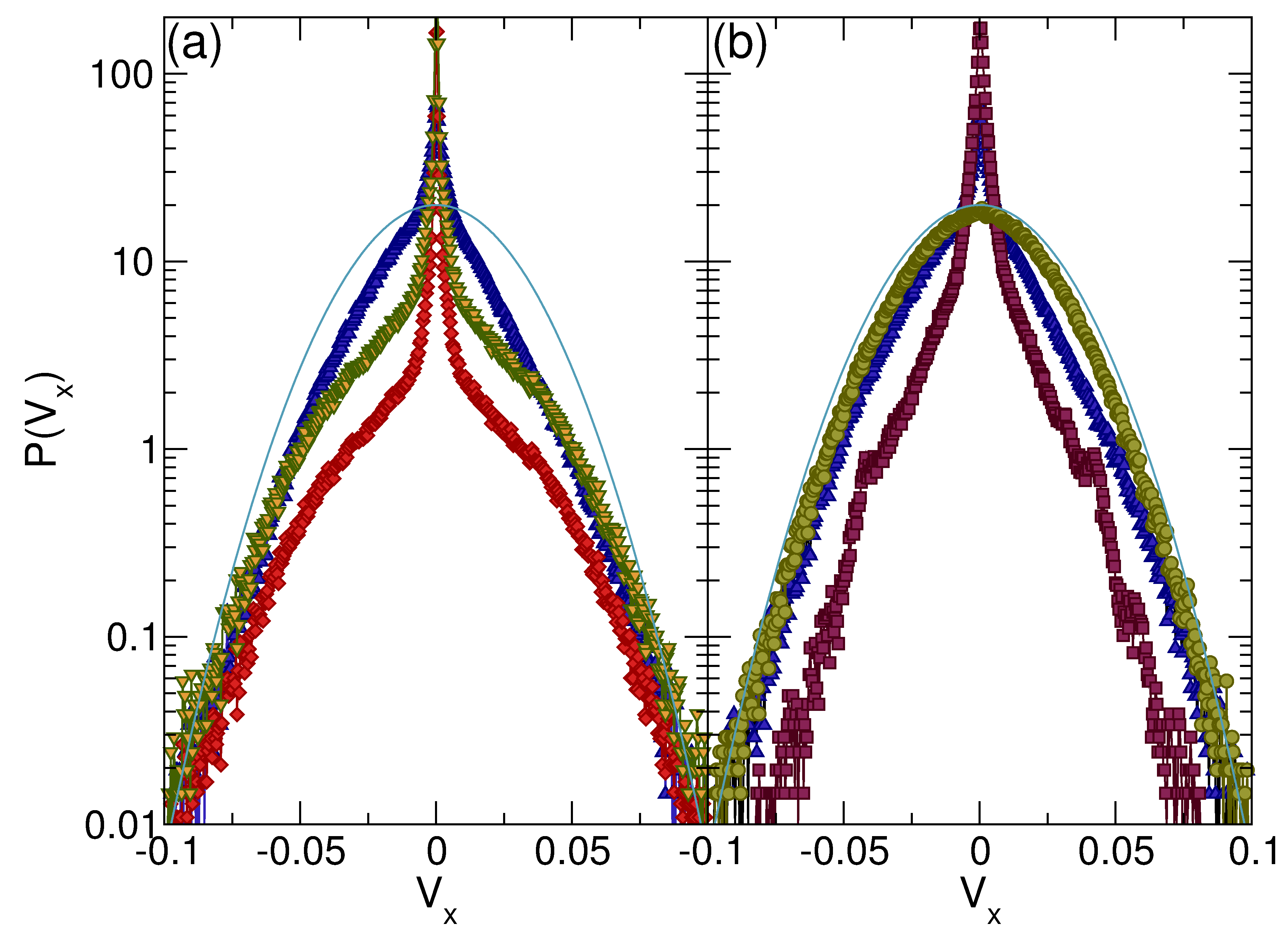
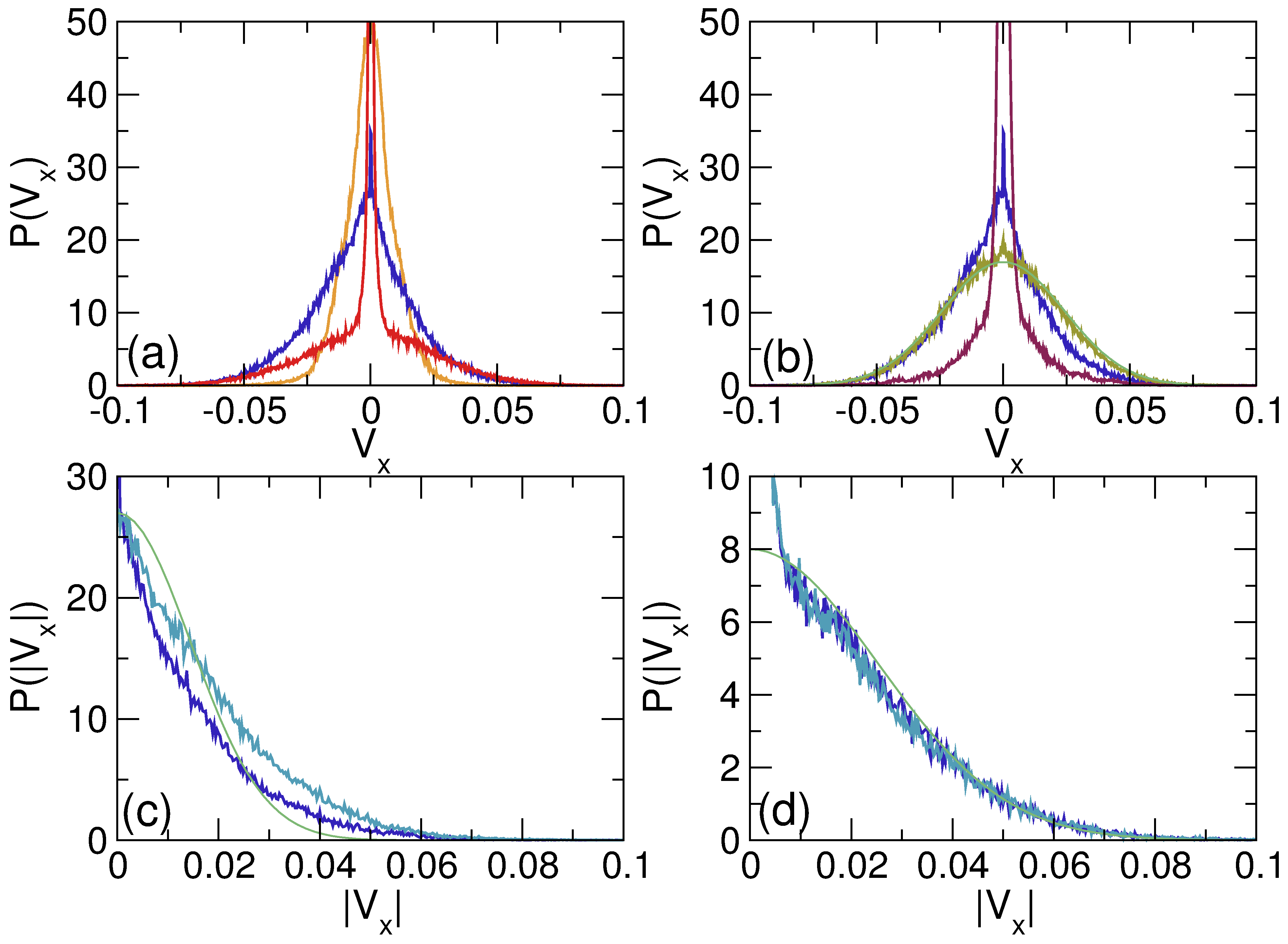
(a) P(Vx) for the ConfG drift ratchet at B/Bϕ = 1.0 and Fp = 1.0 for Fydc = 0.55 (red curve), Fydc = 0.7 (blue curve) where the strongest transverse drift occurs, and Fydc = 0.95 (yellow curve). (b) P(Vx) for the ConfG (blue curve), RandG (brown curve), and SquareG (dark red curve) drift ratchets at B/Bϕ = 1.0, Fp = 1.0, and Fydc = 0.7. The smooth green line indicates a Gaussian fit.
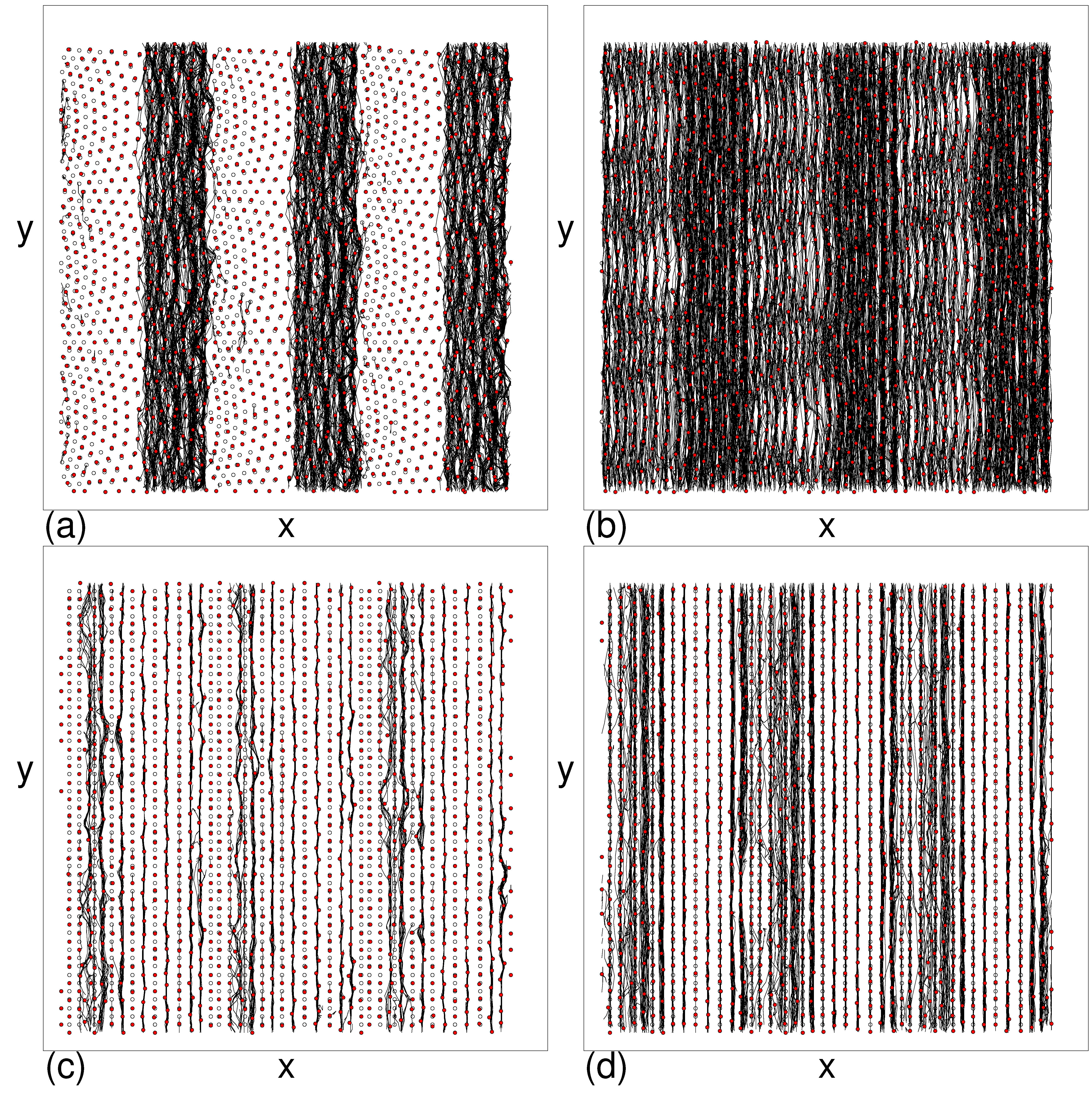
 (c) P(|Vx|) for the ConfG drift ratchet at B/Bϕ=1.0, Fp=1.0, and Fydc = 0.7. The upper light blue curve is for negative Vx values, the lower dark blue curve is for positive Vx values, and the smooth green line is a Gaussian fit. (d) P(|Vx|) for the ConfG drift ratchet at B/Bϕ=1.0, Fp=1.0, and Fydc = 0.55, where there is no net drift. The light blue curve is for negative Vx values, the dark blue curve is for positive Vx values, and the smooth green line is a Gaussian fit. There is little to no asymmetry in the velocity curves, which are both well fit by a Gaussian distribution away from the peak near |Vx|=0.
We next consider the drift ratchet transverse velocity fluctuations measured in the same way as for the ac driven transverse ratchet effect in Section III. In Fig. 20(a) we plot P(Vx) for the ConfG array at B/Bϕ = 1.0 and Fp = 1.0. At Fydc = 0.55, where there is no transverse drift, there is a strong peak in P(Vx) at Vx = 0 since a portion of the vortices are permanently pinned. For Fydc = 0.7 where there is a strong transverse drift ratchet effect, the magnitude of the Vx=0 peak in P(Vx) is reduced since the vortices are only temporarily rather than permanently pinned, while P(Vx) remains large over a wider range of Vx values. At Fydc = 0.95 where the drift effect is diminished, the width of P(Vx) is strongly reduced since the vortices are moving primarily along straighter trajectories aligned with the y-direction. In Fig. 20(b) we plot P(Vx) for the ConfG, RandG, and SquareG arrays at B/Bϕ=1.0, Fp=1.0, and Fydc = 0.7. The SquareG array has a strong peak in P(Vx) at Vx = 0 since the vortices are moving in 1D paths in the y-direction. For the RandG array the velocity fluctuations can be fit to a Gaussian curve as indicated by the smooth solid line. When there is a strong transverse drift ratchet effect, P(Vx) is asymmetric about Vx=0, as shown in Fig. 20(c) where we plot P(|Vx|) separately for Vx > 0 and Vx < 0 in the ConfG array at B/Bϕ=1.0, Fp=1.0, and Fydc = 0.7. There is a clear difference in the velocity distributions for vortices moving in the positive and negative x directions. The smooth curve is a Gaussian fit highlighting the non-Gaussian nature of the fluctuations. In Fig. 20(d) we show P(|Vx|) for positive and negative Vx in the same ConfG array at Fydc = 0.55 where there is no net drift. Here the velocity distribution is symmetric and can be fit to a Gaussian tail away from |Vx|=0.

V.  RATCHET EFFECTS FOR COLLOIDAL PARTICLES

The results we find should be general to a wide class of systems of interacting particles moving over a gradient substrate array where nonequilibrium transverse fluctuations can be dynamically generated. For example, our results could be applied to charge-stabilized colloids interacting with optical trap arrays [58,66]. Charged colloids can be modeled as overdamped particles interacting via a repulsive Yukawa or screened Coulomb potential V(Rij) = Acexp(−κRij)/Rij, where κ is the screening length and Ac is proportional to the effective charge on the particle. Compared to superconducting vortices, the colloids have a much shorter range interaction but a sharper repulsion at the shortest distances. The effective charge and the screening length can be tuned readily in the colloidal system by modifying the ion concentration in the solution. If transverse ratchets can be realized in a colloidal system, they could potentially provide a new spatial separation technique in which a mixture of colloidal species driven over a substrate has one species gradually move further in the drift direction than the other. In previous studies of the longitudinal ratchet effect on conformal substrates, colloidal particles exhibited a robust ratchet effect similar to the superconducting vortices [53].
Fig21.png
Figure 21: (a) Xnet after 50 ac drive cycles vs Ac for colloidal particles interacting with a ConfG array with Fp = 1.0, a filling factor of 1.0, and Fyac = 0.7. Here Ac is the prefactor of the colloidal repulsive interaction term. (b) The corresponding fraction of six-fold coordinated colloids P6 vs Ac. (c) Xnet after 4 ×10⁵ simulation time steps vs Ac for the same system with Fydc = 0.7. (d) The corresponding P6 vs Ac.
In Fig. 21(a) we plot Xnet versus Ac for colloids driven oven a ConfG array with a transverse ac drive Fyac = 0.7 for Fp = 1.0 at a filling fraction of 1.0. In Fig. 21(b) we plot the corresponding fraction of six-fold coordinated colloids P6 versus Ac. For the smallest values of Ac, the colloids are weakly interacting and become localized at the pinning sites so that there is no transverse ratchet. At intermediate values of Ac, where 0.3 < P6 < 0.82, the colloids move in the negative x direction and exhibit a normal transverse ratchet effect, while at slightly higher values of Ac there is a small window in which the ratchet effect is in the reversed positive x direction and 0.9 < P6 < 1.0. This reversed ratchet effect is similar to what we observe for large values of Fyac in the vortex system, and arises when the colloids dynamically order in the low pinning density portions of the sample but remain partially disordered in the high pinning density portions of the sample. For higher values of Ac, when the colloids form a uniform triangular lattice with P6 = 1.0, the flow becomes elastic and the ratchet effect is lost. Figure 21(c) shows Xnet versus Ac for dc driven colloids in the drift ratchet configuration where the drive is applied along the y-direction. Here there is only a normal negative x direction transverse drift effect, and the magnitude of |Xnet| is larger than that for the ac driven sample in Fig. 21(a). At high enough values of Ac, the system again forms a triangular solid with P6 = 1.0 and the transverse drift is lost. These results show that the transverse ratchet and drift ratchet along with ratchet reversals can also be realized in colloidal systems.

VI.  SUMMARY

Using numerical simulations we show that vortices on conformal pinning arrays driven by an ac force applied perpendicular to the array asymmetry direction exhibit a novel transverse ratchet effect where there is a net drift of vortices perpendicular to the ac drive. This effect arises when the dynamically generated nonequilibrium fluctuations which have non-Gaussian characteristics combine with the asymmetry of the substrate to create what is known as a noise correlation ratchet. This ratchet effect is distinct from previously observed transverse vortex ratchet effects that are caused by geometric deflection of individual vortex trajectories. In our system, the correlated noise is generated by the plastic flow of vortices, which creates strong non-Gaussian velocity fluctuations in the direction perpendicular to the ac drive. We find that the transverse ratchet effect is absent for square gradient arrays since these produce less meandering of the vortex trajectories and therefore have reduced velocity fluctuations. The effect is present for random gradient arrays but is substantially weaker than that produced by the conformal array. We show that it is possible to realize a series of reversals in the direction of flow of the transverse ratchet due to changes in the spatial flow pattern of the vortices across gradient. These reversals can occur as a function of vortex density, ac driving amplitide, and pinning strength. The transverse ratchet effect has a magnitude that is about one-half to one-third the size of the longitudinal ratchet effect observed for the same conformal pinning arrays. We also examine the case where a dc drive applied perpendicular to the asymmetry of the substrate produces what is known as a geometric or drift ratchet, where a net flux of vortices perpendicular to the dc drive occurs. The maximum efficiency of the drift ratchet in the conformal array is about 2.5 times larger than that of the corresponding ac driven transverse ratchet. The drift ratchet is also a realization of a noise correlation ratchet, and we find that it exhibits reversals in the drift direction as a function of field, drive amplitude, and pinning strength. Our results should be general to a wide class of systems of interacting particles undergoing dynamically generated fluctuations when driven over a a conformal array, including colloidal particles in optical trap arrays.

  ACKNOWLEDGMENTS

This work was carried out under the auspices of the NNSA of the U.S. DoE at LANL under Contract No. DE-AC52-06NA25396.

References

[1]
P. Reimann, Phys. Rep. 361, 57 (2002).
[2]
P. Hänggi and F. Marchesoni, Rev. Mod. Phys. 81, 387 (2009).
[3]
M.O. Magnasco, Phys. Rev. Lett. 71, 1477 (1993).
[4]
C.R. Doering, W. Horsthemke, and J. Riordan, Phys. Rev. Lett. 72, 2984 (1994).
[5]
P. Galajda, J. Keymer, P. Chaikin, and R. Austin, J. Bacteriol. 189, 8704 (2007).
[6]
M.B. Wan, C. J. Olson Reichhardt, Z. Nussinov, and C. Reichhardt, Phys. Rev. Lett. 101, 018102 (2008).
[7]
A. Van Oudenaarden and S.G. Boxer, Science 285, 1046 (1999).
[8]
D. Ertas, Phys. Rev. Lett. 80, 1548 (1998); T.A.J. Duke and R.H. Austin, Phys. Rev. Lett. 80, 1552 (1998).
[9]
C. Keller, F. Marquardt, and C. Bruder, Phys. Rev. E 65, 041927 (2002).
[10]
J. Herrmann, M. Karweit, and G. Drazer, Phys. Rev. E 79, 061404 (2009).
[11]
S. Savel'ev, V. Misko, F. Marchesoni, and F. Nori, Phys. Rev. B 71, 214303 (2005).
[12]
C.S. Lee, B. Jankó, I. Derényi, and A.L. Barabási, Nature (London) 400, 337 (1999).
[13]
J.F. Wambaugh, C. Reichhardt, C.J. Olson, F. Marchesoni, and F. Nori, Phys. Rev. Lett. 83, 5106 (1999).
[14]
C. J. Olson, C. Reichhardt, B. Jankó, and F. Nori, Phys. Rev. Lett. 87, 177002 (2001).
[15]
J.E. Villegas, S. Savel'ev, F. Nori, E.M. Gonzalez, J.V. Anguita, R. García, and J.L. Vicent, Science 302, 1188 (2003).
[16]
R. Wördenweber, P. Dymashevski, and V. R. Misko, Phys. Rev. B 69, 184504 (2004).
[17]
J. Van de Vondel, C. C. de Souza Silva, B. Y. Zhu, M. Morelle, and V. V. Moshchalkov, Phys. Rev. Lett. 94, 057003 (2005).
[18]
C.C. de Souza Silva, J. Van de Vondel, M. Morelle, and V.V. Moshchalkov, Nature (London) 440, 651 (2006).
[19]
Q. Lu, C. Reichhardt, and C. Reichhardt, Phys. Rev. B 75, 054502 (2007).
[20]
K. Yu, T.W. Heitmann, C. Song, M.P. DeFeo, B.L.T. Plourde, M.B.S. Hesselberth, and P.H. Kes, Phys. Rev. B 76, 220507(R) (2007).
[21]
B.L.T. Plourde, IEEE Trans. Appl. Supercond. 19, 3698 (2009).
[22]
B.B. Jin, B.Y. Zhu, R. Wördenweber, C.C. de Souza Silva, P.H. Wu, and V.V. Moshchalkov, Phys. Rev. B 81, 174505 (2010).
[23]
V.A. Shklovskij and O.V. Dobrovolskiy, Phys. Rev. B 84, 054515 (2011).
[24]
A. Palau, C. Monton, V. Rouco, X. Obradors, and T. Puig, Phys. Rev. B 85, 012502 (2012).
[25]
V.I. Marconi, Phys. Rev. Lett. 98, 047006 (2007).
[26]
V.A. Shklovskij, V.V. Sosedkin, and O.V. Dobrovolskiy, J. Phys.: Condens. Matter 26, 025703 (2014).
[27]
N.S. Lin, T.W. Heitmann, K. Yu, B.L.T. Plourde, and V.R. Misko, Phys. Rev. B 84, 144511 (2011).
[28]
G. Karapetrov, V. Yefremenko, G. Mihajlovi'c, J.E. Pearson, M. Iavarone, V. Novosad, and S.D. Bader, Phys. Rev. B 86, 054524 (2012).
[29]
D. Perez de Lara, F.J. Castaño, B.G. Ng, H.S. Korner, R.K. Dumas, E.M. Gonzalez, K. Liu, C.A. Ross, I.K. Schuller, and J.L. Vicent, Phys. Rev. B 80, 224510 (2009).
[30]
V. Rouco, A. Palau, C. Monton, N. Del-Valle, C. Navau, A. Sanchez, X. Obradors and T. Puig, New J. Phys. 17, 073022 (2015).
[31]
L. Dinis, E.M. González, J.V. Anguita, J.M.R. Parrondo, and J.L. Vicent, Phys. Rev. B 76, 212507 (2007).
[32]
L. Dinis, E.M. González, J.V. Anguita, J.M.R. Parrondo, and J.L. Vicent, New J. Phys. 9, 366 (2007).
[33]
D. Perez de Lara, A. Alija, E.M. Gonzalez, M. Velez, J.I. Martín, and J.L. Vicent, Phys. Rev. B 82, 174503 (2010).
[34]
D. Perez de Lara, M. Erekhinsky, E.M. Gonzalez, Y.J. Rosen, I.K. Schuller, and J.L. Vicent, Phys. Rev. B 83, 174507 (2011).
[35]
J. Van de Vondel, V.N. Gladilin, A.V. Silhanek, W. Gillijns, J. Tempere, J.T. Devreese, and V.V. Moshchalkov, Phys. Rev. Lett. 106, 137003 (2011).
[36]
C. J. Olson Reichhardt and C. Reichhardt, Physica C 432, 125 (2005).
[37]
E.M. Gonzalez, N.O. Nunez, J.V. Anguita, and J.L. Vicent, Appl. Phys. Lett. 91, 062505 (2007).
[38]
A.V. Silhanek, J. Van de Vondel, V.V. Moshchalkov, A. Leo, V. Metlushko, B. Ilic, V.R. Misko, and F.M. Peeters, Appl. Phys. Lett. 92, 176101 (2008).
[39]
D. Perez de Lara, L. Dinis, E.M. Gonzalez, J.M.R. Parrondo, J.V. Anguita, and J.L. Vicent, J. Phys.: Condens. Matter 21, 254204 (2009).
[40]
L. Dinis, D. Perez de Lara, E.M. Gonzalez, J.V. Anguita, J.M.R. Parrondo, and J.L. Vicent, New J. Phys. 11, 073046 (2009).
[41]
T.C. Wu, R. Cao, T.J. Yang, L. Horng, J.C. Wu, and J. Kolacek, Solid State Commun. 150, 280 (2010).
[42]
T.C. Wu, L. Horng, J.C. Wu, R. Cao, J. Kolacek, and T.J. Yang, J. Appl. Phys. 102, 033918 (2007).
[43]
T.-C. Wu, L. Horng, and J.-C. Wu, J. Appl. Phys. 117, 17A728 (2015).
[44]
W. Gillijns, A.V. Silhanek, V.V. Moshchalkov, C.J. Olson Reichhardt, and C. Reichhardt, Phys. Rev. Lett. 99, 247002 (2007).
[45]
D. Ray, C.J. Olson Reichhardt, B. Jankó, and C. Reichhardt, Phys. Rev. Lett. 110, 267001 (2013).
[46]
P. Pieranski, in Phase Transitions in Soft Condensed Matter, T. Riste and D. Sherrington, Eds. (Plenum, New York, 1989), p. 45; F. Rothen, P. Pieranski, N. Rivier, and A. Joyet, Eur. J. Phys. 14, 227 (1993).
[47]
F. Rothen and P. Pieranski, Phys. Rev. E 53, 2828 (1996).
[48]
Y.L. Wang, M.L. Latimer, Z.L. Xiao, R. Divan, L.E. Ocola, G.W. Crabtree, and W.K. Kwok, Phys. Rev. B 87, 220501(R) (2013).
[49]
S. Guénon, Y.J. Rosen, A.C. Basaran, and I.K. Schuller, Appl. Phys. Lett. 102, 252602 (2013).
[50]
M. Motta, F. Colauto, W.A. Ortiz, J. Fritzsche, J. Cuppens, W. Gillijns, V.V. Moshchalkov, T.H. Johansen, A. Sanchez, and A.V. Silhanek, Appl. Phys. Lett. 102, 212601 (2013).
[51]
V.R. Misko and F. Nori, Phys. Rev. B 85, 184506 (2012).
[52]
D. Ray, C. Reichhardt, and C. J. Olson Reichhardt, Phys. Rev. B 90, 094502 (2014).
[53]
C. Reichhardt, D. Ray, and C. J. Olson Reichhardt, Phys. Rev. B 91, 184502 (2015).
[54]
A.C. Marley, M.J. Higgins, and S. Bhattacharya, Phys. Rev. Lett. 74, 3029 (1995).
[55]
C.J. Olson, C. Reichhardt, and F. Nori, Phys. Rev. Lett. 80, 2197 (1998).
[56]
A.B. Kolton, D. Domínguez, and N. Grønbech-Jensen, Phys. Rev. Lett. 83, 3061 (1999).
[57]
A.B. Kolton, Phys. Rev. B 75, 020201 (2007).
[58]
K. Xiao, Y. Roichman, and D.G. Grier, Phys. Rev. E 84, 011131 (2011).
[59]
C. Reichhardt, C. J. Olson, and F. Nori, Phys. Rev. B 57, 7937 (1998).
[60]
G.R. Berdiyorov, M.V. Milosevic, and F.M. Peeters, Phys. Rev. B 74, 174512 (2006).
[61]
G.R. Berdiyorov, M.V. Milosevic, and F.M. Peeters, New J. Phys. 11, 013025 (2009).
[62]
C. Ludwig, Sitzungber Bayer. Akad. Wiss. Wien Math-Naturwiss. Kl. 20, 539 (1856); S. Duhr and D. Braun, Proc. Natl. Acad. Sci. (U.S.A.) 103, 19678 (2006).
[63]
C.J. Olson, C. Reichhardt, and F. Nori, Phys. Rev. Lett. 81, 3757 (1998).
[64]
A.E. Koshelev and V.M. Vinokur, Phys. Rev. Lett. 73, 3580 (1994).
[65]
A.B. Kolton, R. Exartier, L.F. Cugliandolo, D. Domínguez, and N. Grønbech-Jensen, Phys. Rev. Lett. 89, 227001 (2002).
[66]
J. Mikhael, J. Roth, L. Helden, and C. Bechinger, Nature (London) 454, 501 (2008).


File translated from TEX by TTHgold, version 4.00.
Back to Home