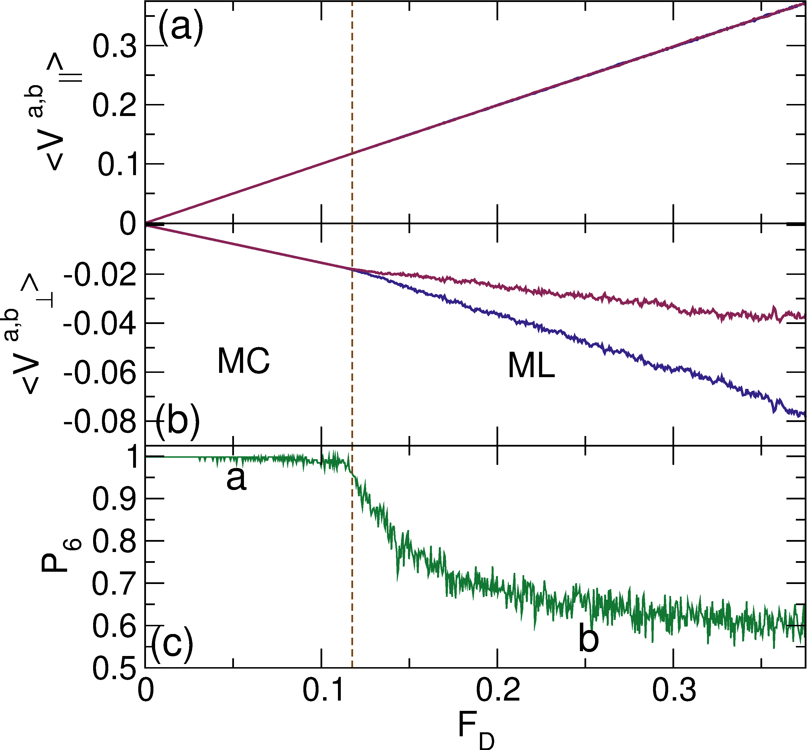
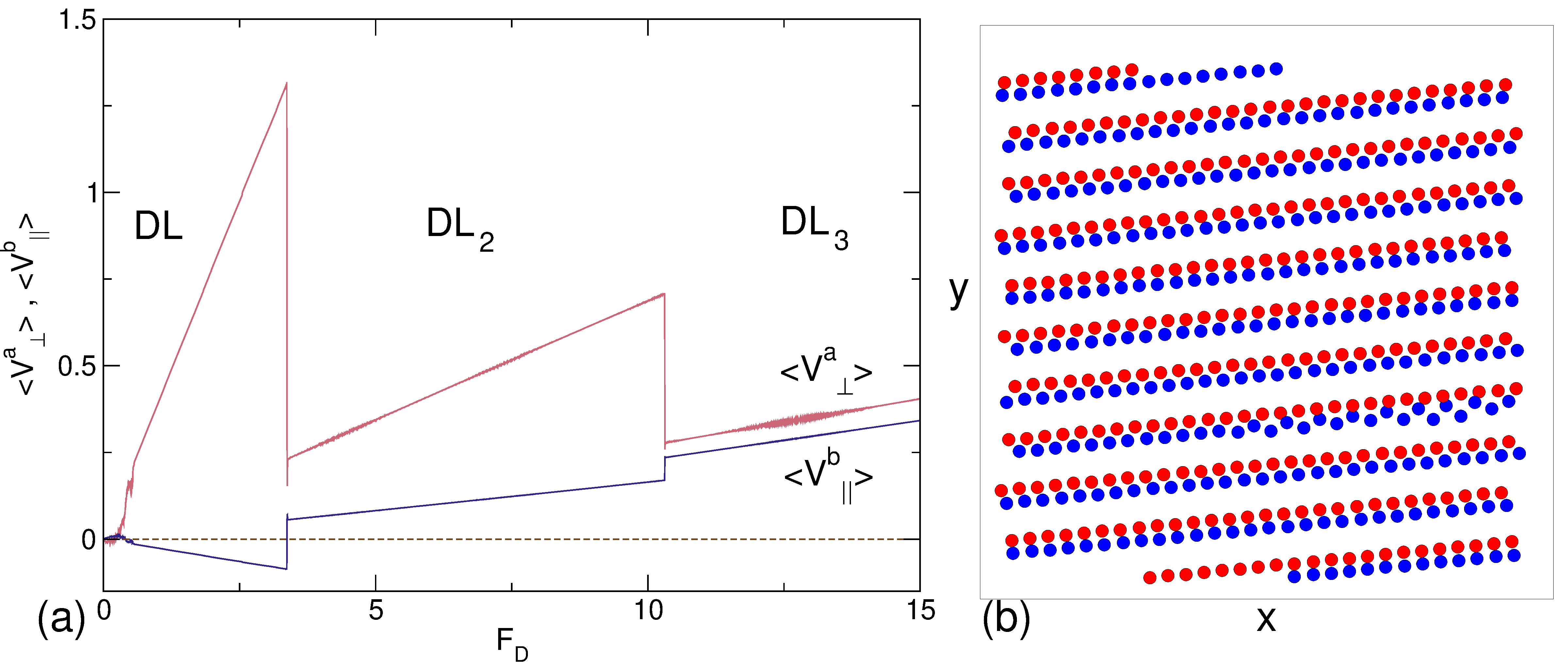
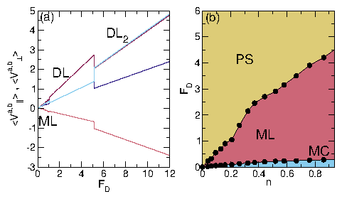
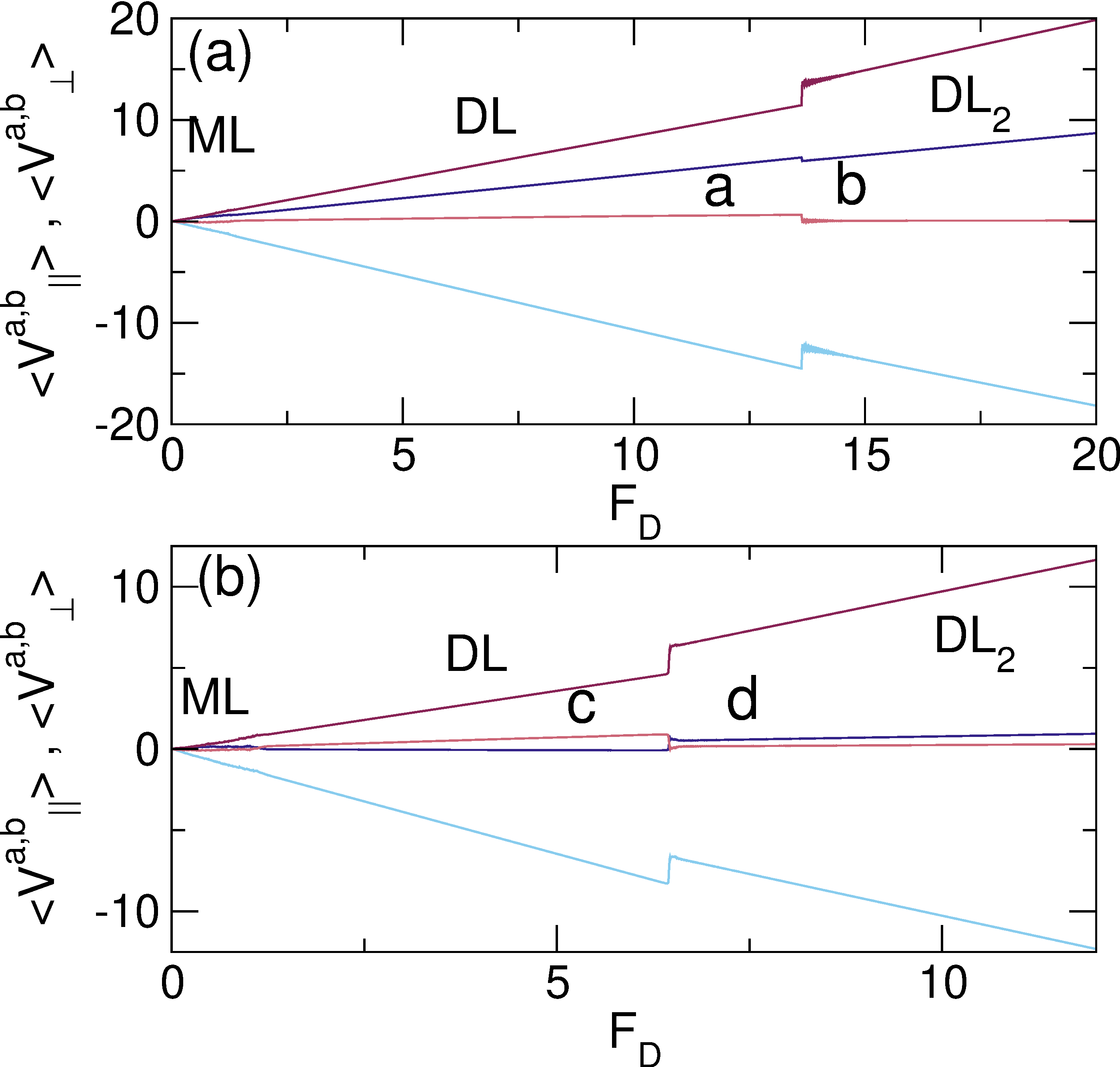
Physical Review E 99, 012606 (2019)

Disordering, Clustering, and Laning Transitions in Particle Systems with Dispersion in the Magnus Term

C. J. O. Reichhardt and C. Reichhardt

Theoretical Division and Center for Nonlinear Studies, Los Alamos National Laboratory, Los Alamos, New Mexico 87545, USA

(Received 24 October 2018; published 9 January 2019)

We numerically examine a two-dimensional system of repulsively interacting particles with dynamics that are governed by both a damping term and a Magnus term. The magnitude of the Magnus term has one value for half of the particles and a different value for the other half of the particles. In the absence of a driving force, the particles form a triangular lattice, while when a driving force is applied, we find that there is a critical drive above which a Magnus-induced disordering transition can occur even if the difference in the Magnus term between the two particle species is as small as one percent. The transition arises due to the different Hall angles of the two species, which causes their motion to decouple at the critical drive. At higher drives, the disordered state can undergo both species and density phase separation into a density modulated stripe that is oriented perpendicular to the driving direction. We observe several additional phases that occur as a function of drive and Magnus force disparity, including a variety of density modulated diagonal laned phases. In general we find a much richer variety of states compared to systems of oppositely driven overdamped Yukawa particles. We discuss the implications of our work for skyrmion systems, where we predict that even for small skyrmion dispersities, a drive-induced disordering transition can occur along with clustering phases and pattern forming states.
I. INTRODUCTION
II. SIMULATION
III. MAGNUS INDUCED DISORDERING TRANSITION
IV. CLUSTER AND STRIPE FORMATION
V. VARIED DAMPING RATIOS
VI. VARIED MAGNUS FORCE
VII. MAGNUS TERMS OF OPPOSITE SIGN
VIII. OTHER VARIABLES AND DISCUSSION
IX. SUMMARY
REFERENCES


I.  INTRODUCTION

There is a wide variety of systems that can be effectively modeled as an assembly of interacting particles that undergoes structural transitions under some form of external driving. In the presence of a random or periodic substrate, the particles can exhibit a depinning transition [1,2] such as that found for superconducting vortices [3,4], colloidal particles [5,6,7], or sliding friction [8]. Disordering or ordering transitions can occur in the absence of quenched disorder as a function of dc or ac shearing [9,10,11,12,13]. In many cases, the particles have a uniform size and particle-particle interaction force, but when the particle sizes or interactions become polydisperse, order-disorder transitions can appear even in the absence of driving or shearing [14,15,16]. Disordering transitions and other dynamical phases can also arise in systems with monodisperse particle-particle interactions if some of the particles have different dynamics than others. A well-studied example is oppositely driven repulsive particles, which can form static ordered states or undergo fluctuating disordered flow that is followed at higher drives by a transition to a laned state consisting of multiple partially phase separated oppositely moving stripes [17,18,19,20,21,22,23,24,25,26]. Similar ordering and laning transitions appear when the particles move at different velocities in the same direction [27]. Experimentally, laning transitions have been realized for colloidal particles [28,29] and dusty plasmas [30,31].
Here we study whether a disordering transition or lane formation can occur for an assembly of bidisperse particles that are all driven in the same direction when each particle species has a different non-dissipative Magnus term. We consider repulsively interacting particles that form a triangular lattice in the absence of a driving force or substrate. A dissipative force of magnitude αdi aligns the velocity of particle i with the net direction of the external forces acting on that particle, while a Magnus term of magnitude αmi aligns the particle velocity perpendicular to the external forces. When we introduce an applied driving force of magnitude FD, we find that if the Magnus term αmi=0 and the dissipative term αdid for all i, the system forms a triangular lattice that moves parallel to the driving direction. If the Magnus term is nonzero but equal for all particles, αmi ≡ αm, a triangular lattice still forms, but it moves at a Hall angle θSkSkint with respect to the driving direction, where the intrinsic Hall angle θSkint = arctan(αmd). If the Magnus term is bidisperse, with a value of αma for half of the particles and αmb > αma for the other half, we find that when αma=0 and αmb ≠ 0, a triangular lattice appears that moves elastically at an angle θSkb,int/2 for small drives. Above a critical drive Fc, dislocation pairs proliferate in the lattice and a dynamical disordering transition occurs when the two species move at different velocities in the directions parallel and perpendicular to the drive due to the drive dependence of θbSk. When αma ≠ 0 and αma < αmb, this behavior persists since the drive dependence of θaSk differs from that of θbSk; however, Fc increases as the difference αmb−αma decreases. At high drives, the disordered state transitions to a cluster or stripe state in which the particles phase separate into a single stripe oriented perpendicular to the drive with one species on each side of the stripe. The stripe becomes denser with increasing FD since θSkb−θSka increases and species a piles up behind species b. Due to the increasing compression of the stripe, eventually an instability occurs in which the system can lower its particle-particle interaction energy by forming a more uniform state that we call a diagonal laned phase. In some cases, the diagonal laned state exhibits strong density modulations as well as additional transitions to a larger number of thinner lanes. All of these transitions are associated with changes and jumps in the average velocity both parallel and perpendicular to the drive, as well as changes in the amount of six-fold ordering in the system.
Our results have implications for driven magnetic skyrmions, which are particlelike magnetic textures that interact repulsively with each other and form a triangular lattice [32,33,34]. Skyrmions can be set into motion by the application of a current [34,35,36,37,38,39,40], and due to the Magnus term they move at an angle with respect to the driving force known as the skyrmion Hall angle [34,41,42,43,44,45]. Within a given sample, there can be dispersion in the size of skyrmions, and different species of skyrmions with different dynamics may be able to coexist with each other [38,45,46,47,48,49,50], so it is important to understand how polydispersity affects the collective motion of skyrmions.
Our results suggest that if there is the slightest dispersion in the Magnus term, a drive-induced disordering transition from a crystal to a liquidlike state can occur even in the absence of quenched disorder. In systems with strong quenched disorder, monodisperse skyrmions depin into a plastically flowing disordered state, but at higher drives they dynamically reorder into a moving crystal state [41,51,52] similar to that found for superconducting vortices [2,3,4,53]. Our results indicate that when there is a dispersion in the Magnus term, such behavior is reversed and the skyrmions disorder at higher drives. In addition, clustering or species segregation can occur. Recent continuum and particle-based simulations of monodisperse skyrmions showed that clustering transitions can occur in samples containing strong pinning or quenched disorder [52,54]. Our results demonstrate that clustering can also occur in the absence of pinning when there is any dispersity in the skyrmions that produces differences in the Magnus term. These results may also be relevant for soft matter systems in which Magnus forces are important, such as magnetic particles in solutions [55,56,57] or spinning colloidal particles [58,59], where different size particles could experience different effective Magnus forces.
The paper is organized as follows. In Sec. II we describe our simulation details. Section III introduces the Magnus induced disordering transition. In Sec. IV we focus on cluster and stripe formation, and show that a nonequilibrium conformal crystal structure can spontaneously emerge in the system. Section V describes the effect of varying the ratio of the damping term for the two species. In Sec. VI we vary the ratio of the Magnus term of the two species for fixed and equal damping terms. We show the results of introducing Magnus terms of opposite sign in Sec. VII. In Sec. VIII we briefly describe the effect of changing other variables and provide a general discussion. A summary of the work appears in Sec. IX.

II.  SIMULATION

We consider a two-dimensional system of size L ×L with periodic boundary conditions in the x and y-directions containing Na particles of species a and Nb particles of species b for a total of N=Na+Nb particles. The particle density is n=N/L2, where L=36. Unless otherwise noted, we take Na=Nb=N/2. The equations of motion for particle i of species γ = a or b is
αγd vi + αγm
^
z
 
×vi = Fssi + FD
(1)
where the particle velocity is vi = d ri/dt. All particle-particle interactions have the same pairwise form of a modified Bessel function, Fiss=∑iNK1(rij)rij that falls off exponentially for large r. Here rij=|rirj| is the distance between particles i and j, and rij=(rirj)/rij. This interaction potential has been used previously for particle-based models of skyrmions, and in the absence of pinning it causes the particles to form a hexagonal lattice [37,41,51,54,60]. For computational efficiency we cut off the skyrmion-skyrmion interaction beyond a length of rij=7.0 when it becomes negligible. The driving force FD=FDx is the same for all particles. We increase the drive in increments of δFD = 0.002 and wait 104 simulation time steps between increments to ensure we are in a steady state. The damping term αγd aligns the particle velocity in the direction of the net applied forces, while the Magnus term αγm generates velocity components that are perpendicular to the net applied forces. As in previous work, unless otherwise noted we normalize the two coefficients such that (αdγ)2 + (αmγ)2 = 1.0 [41,42,60]; however, we also consider systems with fixed αdγ and varied αmγ that are not subject to this constraint. The intrinsic Hall angle for species γ is θγ,intSk = arctan(αmγdγ). It is known from previous work on skyrmion systems with disorder that θSkγ depends on the velocity of the particles and can be written as θSkγ = tan−1(〈Vγ〉/〈V||γ〉) where 〈Vγ〉 = Nγ−1iNγvi ·y and 〈V||γ〉 = Nγ−1iNγvi ·x, with the average taken over time in the steady state [41,42,51,61]. In a system with αambm = 0, θSka = θSkb = 0. We initialize the particles in a triangular lattice and assign Na randomly selected particles to be species a, with the remaining particles set to species b. We measure 〈Va〉, 〈V||a〉, 〈Vb〉, and 〈V||b〉, along with θaSk and θbSk. In our system the typical skyrmion lattice constant is a0=1.5. For reference, in the representative skyrmion-supporting material MnSi, a typical skyrmion lattice constant is 50 nm, typical driving currents range from 108 to 109 A/m2, and the skyrmion Hall angle ranges from 50° to 83° [37].

III.  MAGNUS INDUCED DISORDERING TRANSITION

Fig1.png
Figure 1: 〈Va||〉 (red) and 〈Vb||〉 (blue) vs FD in a sample with αam=0, αad=1, and αbm=0.3. (b) The corresponding 〈Va〉 (red) and 〈Vb〉 (blue) vs FD. For FD < 0.1175, the system forms a moving triangular crystal (MC) and the velocities are locked in both directions, while for FD ≥ 0.1175, the transverse velocity curves split with 〈Vb〉 increasing more rapidly with FD than 〈Va〉, indicating that the two species are now moving at different velocities. (c) The fraction P6 of sixfold-coordinated particles vs FD. For FD < 0.1175, P6 ≈ 1 as expected for a triangular lattice, while P6 drops for FD ≥ 0.1175, indicating a disordering of the system. The letters a and b indicate the values of FD at which the images in Fig. 2 were obtained. The vertical dashed line marks the transition from the moving crystal (MC) to the moving liquid (ML) state.
Fig2.png
Figure 2: Images of particle positions for species a (red) and b (blue) for the system in Fig. 1 with αma=0, αda=1.0, and αmb=0.3 at the drives marked a and b in Fig. 1(c). (a) At FD = 0.05, the system forms a triangular solid that is moving in the positive x and negative y directions. (b) At FD = 0.25, the system is in a moving liquid phase.
Fig3.png
Figure 3: The Hall angles θaSk (pink) and θbSk (green) vs FD for the system in Fig. 1 with αma=0, αda=0, and αmb=0.3. In the moving crystal (MC) phase, the species are locked together and all the particles have θaSkbSk = −8.73°, while in the disordered moving liquid (ML) state, the magnitude of θaSk decreases toward 0° while θbSk gradually approaches θb,intSk=−17.45°, marked by a dashed line.
We first consider a system containing N = 572 particles at a density of n = 0.4413 which forms a triangular solid when FD=0. We fix species a in the overdamped limit with αam = 0 and αad = 1.0, while species b has αbm = 0.3 and (αbm)2+(αbd)2=1.0. In Fig. 1(a) we plot the average velocities 〈Va||〉 and 〈Vb||〉 versus FD, and in Fig. 1(b) we show the corresponding 〈Va〉 and 〈Vb〉 versus FD curves. In Fig. 1(c) we plot P6, the overall fraction of sixfold coordinated particles, versus FD. Here P6=N−1iN δ(zi−6), where zi is the coordination number of particle i obtained from a Voronoi tessellation. When FD < 0.1175, we have 〈Va〉/〈Vb〉 = 〈Va||〉/〈Vb||〉 = 1.0 and P6 = 1.0, indicating that the system forms a triangular lattice which moves elastically in the positive x and negative y directions. Here, the skyrmions do not exchange neighbors as they move, and any local fluctuations in position are invariant with respect to the global drift velocity.
We illustrate the particle positions at FD=0.05 in Fig. 2(a), where a moving crystal (MC) phase appears. At FD = 0.1175, a disordering transition occurs that is associated with a drop in P6 caused by the proliferation of 5-7 defect pairs. At this same drive, the 〈Va〉 and 〈Vb〉 curves in Fig. 1(b) split, and the 〈Vb〉 curve increases more rapidly with FD than the 〈Va〉 curve, indicating that the disordering transition is triggered by a partial decoupling of the two species, which now move at different transverse velocities. In Fig. 2(b) we show the particle positions at FD = 0.25 where the system has disordered but the particle species remain mixed. In this moving liquid (ML) phase, the particles undergo continual dynamical rearrangements. Despite the fact that αam = 0, 〈Va〉 continues to increase with increasing FD in the ML phase, indicating that although the two species are no longer fully coupled, species b is able to drag species a in the transverse direction. The vertical dashed line in Fig. 1 marks the MC-ML transition and shows that the longitudinal velocities 〈Va||〉 and 〈Vb||〉 in Fig. 1(a) are not affected by the transition. In Fig. 3 we plot the drive dependent Hall angles θaSk and θbSk versus FD for the system in Fig. 1, where the intrinsic Hall angles are θa,intSk=0° and θb,intSk=−17.45°. In the MC state, both species are locked to the same Hall angle, θaSkbSk ≈ θb,intSk/2 = −8.73°, and at the disordering transition, θaSk approaches 0° while θbSk approaches its intrinsic value of θb,intSk=−17.45°.
Fig4.png
Figure 4: (a) Fc, the drive at which the MC-ML transition occurs, vs αbm for the system in Fig. 1 with αam = 0 and αad=1.0. The solid line is a power law fit to FcCbm)β with C = 0.0323 and β = −1.05. (b) Fc vs αbm in a system with fixed αam = 0.7 for αadbd=1.0, showing a divergence at αbmam = 1.0.
In Fig. 4(a) we plot the critical force Fc, equal to the drive at which the MC-ML transition occurs, versus αbm for the system in Fig. 1 with αma=0 and αda=1.0. As αbm increases, the disordering transition shifts to lower drives, and we find that the critical force can be fit to FcCbm)β with C = 0.0323 and β = −1.05. These results show that even when the Magnus term is very small, application of an external drive can induce a disordering transition. We note that under our imposed normalization constraint, αmb < 1.0. In skyrmion systems, all the particles have a finite Magnus term, so in Fig. 4(b) we plot Fc versus αbm for a system in which we vary αbm while fixing αam=0.7 with αad = αbd=1.0. Here Fc diverges at αbmam = 1.0 according to Fc ∝ |αam − αbm|−1.

IV.  CLUSTER AND STRIPE FORMATION

Fig5.png
Figure 5: (a) 〈Va||〉 (red) and 〈Vb||〉 (blue) vs FD for the system from Fig. 1 with αam=0, αad=1.0, and αbm=0.3. (b) The corresponding 〈Va〉 (red) and 〈Vb〉 (blue) vs FD. (c) The corresponding P6 vs FD. MC is the moving crystal state. There is a transition at FD=2.5 from the moving liquid (ML) phase to a perpendicular stripe (PS) or cluster phase.
In Fig. 5(a,b) we plot 〈Va||〉, 〈Vb||〉, 〈Va〉, and 〈Vb〉 versus FD for the system in Fig. 1 with αma=0, αda=1.0, and αbm = 0.3, while in Fig. 5(c) we show the corresponding P6 versus FD curve. Here we consider values of FD that are much higher than those presented in Fig. 1 in order to access the transition from the ML state to a phase separated (PS) cluster state. The ML phase ends at FD=2.5, where we find a jump of 〈Va〉 to 〈Va〉 = 0, indicating that the motion of species a has locked to the x direction, parallel to the applied driving force. This jump coincides with a jump in 〈Vb〉 to more negative values, and both curves are much smoother above the jump, indicating that fluctuations are reduced in the PS state compared to the ML flow. The ML-PS transition is also associated with a jump up in P6 from P6=0.55 in the ML phase to P6=0.9 in the PS phase as the system becomes more ordered into a moving perpendicular stripe.
Fig6.png
Figure 6: Images of particle positions for species a (red) and b (blue). (a) At FD = 4.0 for the system in Fig. 5 with αda=1.0, αma=0, and αbm=0.3, a perpendicular stripe (PS) state forms with a conformal crystal structure on each side. (b) The PS state for a system with αda=1.0, αma=0, and αbm = 0.75 at FD = 6.0, where the stripe is more compressed.
In Fig. 6(a) we show the particle configurations from the sample in Fig. 5(a) at FD = 4.0 in the PS phase, where the particles undergo species and density phase separation into a partially clustered state consisting of a stripe aligned in the y direction, perpendicular to FD. The particle density is highest at the center of the stripe. Species a moves only along the x-direction, causing it to pile up behind species b, which is moving in both the positive x and negative y directions. As a result, the entire pattern translates in the positive x direction, and the two halves of the pattern shear against each other along the y direction. In Fig. 5(a), 〈Vb||〉 is slightly higher than 〈Va||〉 in the ML phase, but in the PS phase 〈Vb||〉 and 〈Va||〉 become locked together.
There is considerable local sixfold ordering of the particles in the PS state illustrated in, Fig. 6(a), but due to the density gradient the lattice is distorted into conformal arch-like patterns. Conformal crystals arise in two-dimensional systems of repulsive particles in the presence of some form of density gradient, such as magnetic particles in a gravitational field [62], vortices in a Bean state [63,64,65,66], and colloidal particles under a gradient that is imposed by the system geometry [67]. The conformal crystals are the result of a competition between the local sixfold ordering favored by the repulsive particle-particle interactions and the need to spatially vary the interparticle spacing in order to accommodate the density gradient. Most conformal crystals have been observed under equilibrium conditions, while the conformal crystal structure illustrated in Fig. 6(a) is a strictly nonequilibrium state. As FD increases, the conformal stripe state becomes more compressed along the x direction. Increasing αbm also compresses the PS stripe, as illustrated in Fig. 6(b) for a system with αam=0, αda=1.0, and αbm = 0.7 at FD = 5.0. The width of the stripe is controlled by both αm and FD. For fixed FD, the stripe decreases in width with increasing αm, while for fixed αm the stripe decreases in width with increasing FD. We also note that Fig. 6(b) shows an increase in the fluctuations along the interface of the two species for the thiner stripes. This is a result of the increase in the strength of the repulsive skyrmion-skyrmion interactions as the stripes become thin, which eventually leads to the instability of the stripe and the transition to a configuration with a more uniform density.
Fig7.png
Figure 7: (a) 〈Va||〉 (red) and 〈Vb||〉 (blue) vs FD for a system with αam=0, αad=1.0, and αbm=0.7 in the region on either side of the ML (moving lattice) to PS (perpendicular stripe) transition. (b) The corresponding 〈Va〉 (red) and 〈Vb〉 (blue) vs FD curves. The dashed line indicates 〈V〉 = 0. The ML-PS transition is accompanied by a locking of the parallel velocities and a jump in the perpendicular velocities.
In Fig. 7(a) we plot 〈Va||〉 and 〈Vb||〉 versus FD for the system in Fig. 6(b) with αbm=0.7 in the vicinity of the ML-PS transition, while in Fig. 7(b) we show the corresponding 〈Va〉 and 〈Vb〉 versus FD curves. There is a clear parallel velocity locking, with 〈Va||〉/〈Vb||〉 = 1.0 in the PS state, while 〈Va〉 locks to zero velocity at the transition at the same time as a jump in 〈Vb〉 to a more negative value appears. The velocity fluctuations are reduced in the more ordered PS phase compared to the disordered ML state.
Fig8.png
Figure 8: (a) 〈Va||〉 (red) and 〈Vb||〉 (blue) vs FD for a system with αam=0, αad=1.0, and αbm = 0.75 showing that the ML (moving lattice) to PS (perpendicular stripe) transition is followed by a second transition to a diagonal laned (DL) state near FD = 7.75 that is accompanied by large velocity jumps. (b) The corresponding 〈Va〉 (red) and 〈Vb〉 (blue) vs FD curves.
Fig9.png
Figure 9: Images of particle positions for species a (red) and b (blue) for the diagonal laned (DL) state. (a) The system in Fig. 8 with αad=1.0, αam=0, and αbm=0.75 at FD=8.0. (b) A system with αad=1.0, αam=0, and αbm = 0.85, showing the increased compression of the diagonal stripes.
When FD or αbm is increased, the stripes become more compressed and the particle-particle interactions become strong enough to generate an instability that causes the system to enter a different phase consisting of multiple lanes with a more uniform particle density. In Fig. 8 we plot 〈Va||〉, 〈Vb||〉, 〈Va〉, and 〈Vb〉 versus FD for a system with αbm = 0.75. There is a large jump in the velocities near FD = 7.75, where the system undergoes a transition from the PS state to what we term a diagonal laned (DL) state. As illustrated in Fig. 9(a) for FD = 8.0, this state is composed of multiple stripes of particles oriented at an angle to the driving direction. Within each stripe, the density gradient is reduced compared to what is observed in the PS state. At the transition into the DL state, 〈Va||〉 jumps up since species b no longer blocks the motion of species a along the x direction. At the same time, there is a downward jump in 〈Vb||〉 since species b is no longer being pushed as hard in the x direction by species a. Interestingly, a small downward jump in 〈Vb〉 occurs at the PS-DL transition, indicative of negative differential conductivity. This jump is produced by a Magnus force induced velocity imparted by species a to species b. In the PS phase, species a pushes against species b along the x direction, and due to the Magnus term, additional velocity components arise for species b in the negative y-direction. In the DL state, the tilt of the stripes diminishes the magnitude of the x-direction push from species a on species b, which reduces the Magnus force contribution to the y-direction velocity of species b. At the same time, species a now has a negative y direction component of force on species b that generates a negative x direction velocity component of species b through the Magnus term. This produces the drop in 〈Vb||〉 at the PS-DL transition. As αbm increases, the PS-DL transition shifts to lower values of FD, and when αbm ≥ 0.85, the system passes directly from the ML to the DL phase without forming a PS state. In Fig. 9(b) we illustrate the DL state at αbm=0.85 and FD = 8.0, where the number of stripes has increased. Within the DL phase, the stripes become more compressed as FD increases until a transition occurs to a new diagonal laned state, DL2, containing a larger number of stripes with fewer rows of particles in each stripe.
Fig10.png
Figure 10: (a) 〈Va||〉 (dark red), 〈Vb||〉 (dark blue), 〈Va〉 (pink), and 〈Vb〉 (light blue) vs FD for a system with αam=0, αad=1.0, and αbm = 0.9. The system passes directly from the ML (moving lattice) state to the DL (diagonal laned) state, followed by a transition to the DL2 (second diagonal laned) state near FD = 13.5. (b) The same for a system with αam=0, αad=1.0, and αbm = 0.998. The letters a, b, c, and d indicate the values of FD at which the images in Fig. 11 were obtained.
Fig11.png
Figure 11: Images of particle positions for species a (red) and b (blue). (a) The DL state for the system in Fig. 10(a) with αda=1.0, αma=0, and αmb=0.9 at FD = 10.35. (b) The DL2 state from Fig. 10(a) at FD = 14.75. (c) The DL state from the system in Fig. 10(b) with αda=1.0, αma=0, and αmb=0.998 at FD = 5.0. (c) The DL2 state from the system in Fig. 10(b) at FD = 7.5.
In Fig. 10(a) we plot 〈Va||〉, 〈Vb||〉, 〈Va〉, and 〈Vb〉 versus FD for a system with αbm = 0.9, which transitions directly from the ML to the DL phase. A second transition appears near FD = 13.5, as indicated by the jumps in the velocity curves, which corresponds to a rearrangement into the more uniform laned state DL2. In Fig. 11(a) we illustrate the DL state for the system in Fig. 10(a) at FD = 10.3, where the particles form a series of diagonal stripes, each of which is composed of three rows of each species on either side. At FD = 14.75 in the DL2 phase, as shown in Fig. 11(b), there are still two to three rows of particles on each side of each stripe, but the stripes are much more spread out so that the particle density is considerably more uniform. In Fig. 10(b), we plot 〈Va||〉, 〈Vb||〉, 〈Va〉, and 〈Vb〉 versus FD for a system with αbm=0.998 where αbmbd = 15.79, in which the same phases appear but the DL-DL2 transition is shifted to a lower drive of FD = 6.5. Figure 11(c) shows an image of the DL phase for the system in Fig. 10(b) at FD = 5.0, where dense tilted stripes appear, each of which contains four to five rows of particles on each side. In Fig. 11(d), the DL2 phase for the same system at FD = 7.5 has a larger number of lower density stripes containing two rows of particles on each side, giving a more uniform particle density. The exact particle configurations in the DL states are not unique, but generally we find a small number of diagonal stripes with three or more rows of particles on each side of each stripe in the DL phase, while the DL2 phase is more uniform and each of the more numerous stripes has two to three rows of particles on each side. As FD is further increased, the stripes in the DL2 phase become more compressed, and an additional transition can occur to a DL3 state in which each stripe has only a single row of particles on each side.
Fig12.png
Figure 12: Dynamic phase diagram as a function of FD vs αbmbd for the system in Fig. 10 with αad = 1.0 and αam = 0. MC: moving crystal; ML: moving liquid; PS: perpendicular stripe; DL: diagonal laned phase; DL2: second diagonal laned phase.
From the features in the transport curves and changes in the particle configurations, we construct the dynamical phase diagram shown in Fig. 12 as a function of FD versus αbmbd for samples with fixed αad = αbd = 1.0 and αam = 0. The extent of the MC phase increases as αbmbd goes to zero, and similarly the ML-PS transition shifts to higher FD as αbmbd decreases. The PS phase only occurs when αbmbd < 0.85, while for higher values of αbmbd the system transitions directly from the ML phase to the DL state. The DL2 state appears when αbmbd ≥ 0.9.

V.  VARIED DAMPING RATIOS

Fig13.png
Figure 13: (a) 〈Va||〉 (red) and 〈Vb||〉 (blue) vs FD for a system with αambm = 0, αad = 1.0, and αbd = 2.0. (b) The corresponding 〈Va〉 (red) and 〈Vb〉 (blue) vs FD, which both fluctuate around zero but show a clear change in the magnitude of the fluctuations near FD = 2.1. (c) The corresponding P6 vs FD showing the moving crystal (MC), moving liquid (ML), and laning states.
Fig14.png
Figure 14: Images of particle positions for species a (red) and b (blue). (a) The system in Fig. 13 with αambm=0, αda=1.0, and αdb=2.0 in the laned state at FD = 2.5. (b) The laned state for a system with αammb=0, αda=1.0, and αbd = 10 at FD=2.5.
Fig15.png
Figure 15: Dynamic phase diagram as a function of FD vs αadbd for the system in Figs. 13 and 14 with αambm=0 and αda=1.0, showing the moving crystal (MC), moving liquid (ML), and laned states.
We next consider systems in which αam and αbm are both set equal to zero as the damping constant ratio is varied. We fix αad = 1.0 and vary αbd. This is very similar to systems of oppositely driven particles [27], but here both species are moving in the same direction. In Fig. 13(a,b) we plot 〈Va||〉, 〈Vb||〉, 〈Va〉, and 〈Vb〉, for a system with αad = 2.0. Since the Magnus force is zero, 〈Va〉 and 〈Vb〉 both fluctuate around zero. At low drives, 〈Va||〉 and 〈Vb||〉 are locked together and the system forms an elastic triangular solid in the moving crystal state. As the drive increases, there is a transition to a moving liquid phase in which the species a particles, which have a smaller damping coefficient, move faster in the direction of drive than the species b particles, which have higher damping. At FD ≈ 2.1, there is an abrupt decrease in the magnitude of the fluctuations in both 〈Va〉 and 〈Vb〉 as well as a cusp in 〈Va||〉 and 〈Vb||〉, above which the velocities parallel to the drive increase linearly with drive. In Fig. 13(c) we plot P6 for all the particles versus FD, where we find that P6 = 1.0 in the ordered MC phase. At the transition to the ML phase, P6 drops, but for drives above FD=2.1, there is a recovery of order to P6 ≈ 0.9 as the system enters a uniform laned state of the type illustrated in Fig. 14(a) for FD = 2.5. This laned state is the same as that found for oppositely driven Yukawa particles [19], and it is relatively ordered due to the large patches of triangular lattice that appear. Sliding of adjacent lanes past each other is made possible by the presence of aligned 5-7 dislocation pairs that can glide parallel to the driving direction, which give the state a smectic character. The zero Magnus term laned state is distinct from the DL and DL2 states that appear for a finite Magnus term in that the lanes are aligned with the driving direction and the particle density is uniform for all values of FD and αbd, unlike the DL and DL2 states, which can show strong density modulations. In Fig. 14(b) we illustrate that the laned state for αbd = 10 has features similar to the laned states that form at lower αbd. In Fig. 15 we construct a dynamic phase diagram as a function of FD versus αbdad, and highlight the MC, ML, and laned states. As αbdad → 1, there is a divergence in the value of FD at which the MC-ML transition occurs, along with a similar divergence of the transition from the ML to the laned state.

VI.  VARIED MAGNUS FORCE

Fig16.png
Figure 16: (a) 〈Va||〉 (red) and 〈Va〉 (blue) vs FD for a system with αdadb=1.0, αma=0, and αmb=6.0. (b) The corresponding 〈Vb||〉 (red) and 〈Vb〉 (blue) vs FD. The dashed lines indicate zero velocity, showing that there is a regime in which 〈Vb||〉 becomes more negative as FD increases, meaning that species b is exhibiting absolute negative mobility.
Fig17.png
Figure 17: Images of particle positions for species a (red) and b (blue) for the system in Fig. 16 with αdadb=1.0, αam=0, and αbm = 6.0. (a) The moving liquid state at FD=0.5, just before the transition into the diagonal laned (DL) state. (b) The DL state at FD = 1.25. (c) The DL state at FD = 3.0 where the stripes are more compressed. (d) The DL2 state at FD = 3.75.
We next relax the constraint αmb+ αdb = 1.0 and hold αadbd=1.0 while fixing αam = 0.0 and increasing αbm from αbm=0 to αbm=40. This protocol produces more pronounced differences in the longitudinal and transverse velocities of the two species. In Fig. 16(a) we plot 〈Va||〉 and 〈Va〉 versus FD for a system with αbm=6.0, and in Fig. 16(b) we show the corresponding 〈Vb||〉 and 〈Vb〉 versus FD. When FD < 0.6, we observe a disordered or partially disordered state, as illustrated in Fig. 17(a) at FD = 0.5, where a diagonal stripe is beginning to form.
For FD > 0.6 the system enters a DL state as shown in Fig. 17(b) for FD = 1.25, where the lanes are aligned at an angle of roughly θl=60° to the driving direction. Within the DL state, 〈Va||〉 and 〈Va〉 are both positive, indicating that species a is sliding along the positive x and positive y directions due to the orientation of the lane. In contrast, 〈Vb||〉 and 〈Vb〉 are both negative, indicating that species b is moving opposite to the direction of the applied drive, a phenomenon that is known as absolute negative mobility [68,69,70,71]. The strong Magnus force of the species b particles rotates the FD component of the velocity mostly into the negative y direction, leaving a residual positive x direction velocity. The overdamped species a particles move parallel to the driving direction and pile up behind the species b particles, exerting a force of magnitude Fss on them in both the positive x and negative y directions with components Fsscosθl and Fsssinθl, respectively. Under the Magnus force rotation, the Fsscosθl portion of the particle-particle interaction produces a species b velocity contribution that is mostly in the negative y direction, while the Fsssinθl portion of the interaction gives a velocity contribution that is mostly in the negative x direction. Since the positive x direction velocities from FD and Fsscosθl are small, the net value of 〈Vb||〉 is negative, resulting in the absolute negative mobility that we observe. As FD increases, the drift velocity of the entire diagonal lane in the positive x direction increases due to the increase in 〈Va||〉, but at the same time the lane becomes more compressed, decreasing the distance between the species a and species b particles at the center of the lane, and increasing the particle-particle interaction force that is responsible for generating the negative value of 〈Vb||〉. As a result, 〈Vb||〉 becomes more negative with increasing FD.
We note that in previous studies of overdamped systems in which negative mobility is observed, the particles are coupled to some type of asymmetric substrate [68,69,70,71]. Magnus force-induced negative mobility was predicted to occur for monodisperse skyrmions, but only when the skyrmions are coupled to a substrate [72]. The bidisperse system we consider here is unique in that a negative mobility can appear in the absence of a substrate.
The compression of the diagonal lane becomes more intense with increasing FD, as illustrated in Fig. 17(c) at FD=3.0 for the αmb=6.0 system, until a transition occurs at sufficiently high drive to the more uniform DL2 state shown in Fig. 17(d) at FD = 3.75. The DL-DL2 transition is accompanied by a jump up in 〈Va||〉 and a drop in 〈Va〉 since the lanes are now aligned closer to the driving direction at an angle of θl=20°. This change in lane orientation also causes 〈Vb||〉 to abruptly jump from a negative value to a positive value at the DL-DL2 transition.
Fig18.png
Figure 18: 〈Va〉 (pink) and 〈Vb||〉 (blue) vs FD for the system in Fig. 17 with αdadb=1.0, αma=0, and αmb=6.0 showing jumps at the PS-DL, DL-DL2, and DL2-DL3 transitions. (b) Images of particle positions for species a (red) and b (blue) in the DL3 state at FD = 10.5.
In Fig. 18(a) we plot 〈Vb||〉 and 〈Va〉 versus FD for a sample with αbm = 6.0. Here, the negative value of 〈Vb||〉 is more clearly visible. At higher drives we find an additional jump in both 〈Vb||〉 and 〈Va〉 due to rearrangements that transform the DL2 structure into what we call the DL3 state, illustrated Fig. 18(b) for FD=10.5. The DL3 lanes are very thin and are nearly aligned with the x direction.
Fig19.png
Figure 19: Dynamic phase diagram as a function of FD vs αbm for a system with αam = 0 and αad = αbd = 1.0 illustrating the moving crystal (MC), moving liquid (ML), perpendicular stripe (PS), and diagonal laned (DL, DL2, and DL3) phases. A regime of negative mobility for species b appears in phase DL.
In Fig. 19 we construct a dynamic phase diagram as a function of FD versus αbm for the system in Figs. 17 and 18. We find that the width of the moving crystal phase diverges as αbm → 0, while the PS phase only occurs when αbm < 0.5. These results show that the phases we observe are generic in systems where the damping coefficient is fixed but the Magnus term varies.

VII.  MAGNUS TERMS OF OPPOSITE SIGN

Fig20.png
Figure 20: (a) 〈Va||〉 (dark red), 〈Vb||〉 (dark blue), 〈Va〉 (pink), and 〈Vb〉 (light blue) vs FD in a system with αam = 1.0, αbm = −1.0, and αad = αbd = 1.0. (b) The corresponding P6 vs FD. At low drives we find a moving crystal (MC) state, followed by moving liquid (ML) and perpendicular laned (PL) phases.
Fig21.png
Figure 21: Images of particle positions for species a (red) and b (blue). (a) The system in Fig. 20 with αma=1.0, αmb=−1.0, and αdadb=1.0 at FD = 1.5 showing the formation of a uniform perpendicular laned (PL) state oriented transverse to the driving direction. (b) A system with αam = 1.0, αbm=−1.0, αad = 1.0, and αbd = 3.0, in which the PL state shows compression or clustering.
Up to now we have focused on systems in which the Magnus term is zero for one or both species, or where both species have a finite Magnus force with the same sign but different magnitude. Here we examine the case where both species have a nonzero Magnus term of equal magnitude that is opposite in sign. In Fig. 20(a) we plot 〈Va||〉, 〈Vb||〉, 〈Va〉, and 〈Vb〉 versus FD for a system with αam = 1.0, αbm=−1.0, and αad = αbd=1.0, while in Fig. 20(b) we show the corresponding P6 versus FD curve. Here 〈Va〉 is negative while 〈Va||〉, 〈Va〉, and 〈Vb||〉 are all positive. At low FD the system is in an elastic MC state, and it transitions with increasing drive into a moving liquid in which P6 ≈ 0.45. An ordering transition occurs near FD = 0.75, as indicated by the increase in P6 to a value close to P6=0.865, and simultaneously 〈Va||〉 and 〈Vb||〉 lock with 〈Vb〉 as the system enters what we term a perpendicular laned (PL) state, illustrated in Fig. 21(a) at FD = 1.5. The PL structure is very similar to the lanes that form for oppositely driven Yukawa particles, except in this case the lanes are oriented perpendicular to the drive. The PL state is distinguished from the PS state by the fact that the density of the system remains uniform out to arbitrarily high drives in the PL phase. In general, we find no significant density modulations whenever αam and αbm are of the same magnitude but opposite in sign as long as αadbd, even when αam or FD are very large. By setting the damping terms of the two species to different values, it is possible to induce clustering in the PL state with αam=−αbm, as illustrated in Fig. 21(b) for a system with αam = 1.0, αbm = −1.0, αad = 1.0, and αbd = 3.0, where the perpendicular lanes are now compressed. This compression arises because species a, which has a smaller damping term than species b, moves faster and collides with the band of slower moving particles, while the opposite sign of the Magnus terms for the two species is responsible for creating the perpendicular banding.
Fig22.png
Figure 22: Dynamic phase diagram as a function of FD vs αam for the system in Fig. 20 with αdadb=1.0 and αbm=−αam showing the moving crystal (MC), moving liquid (ML), and perpendicular laned (PL) phase.
In Fig. 22 we construct a dynamic phase diagram as a function of FD versus αam for the system in Fig. 20 with αbm=−αam, highlighting the fact that the widths of the MC and ML phases diverge upon approaching the overdamped limit of αam=0. The ML phase also increases in extent with increasing αam when αam > 5.0.

VIII.  OTHER VARIABLES AND DISCUSSION

Fig23.png
Figure 23: (a) 〈Va||〉 (dark red), 〈Vb||〉 (dark blue), 〈Va〉 (pink) and 〈Vb〉 (light blue) versus FD for a system with αbd = 1.0, αad = 2.0, αam = 0.1, and αbm = −1.0, where a series of pronounced jumps indicate transitions into different DL and DL2 phases. 
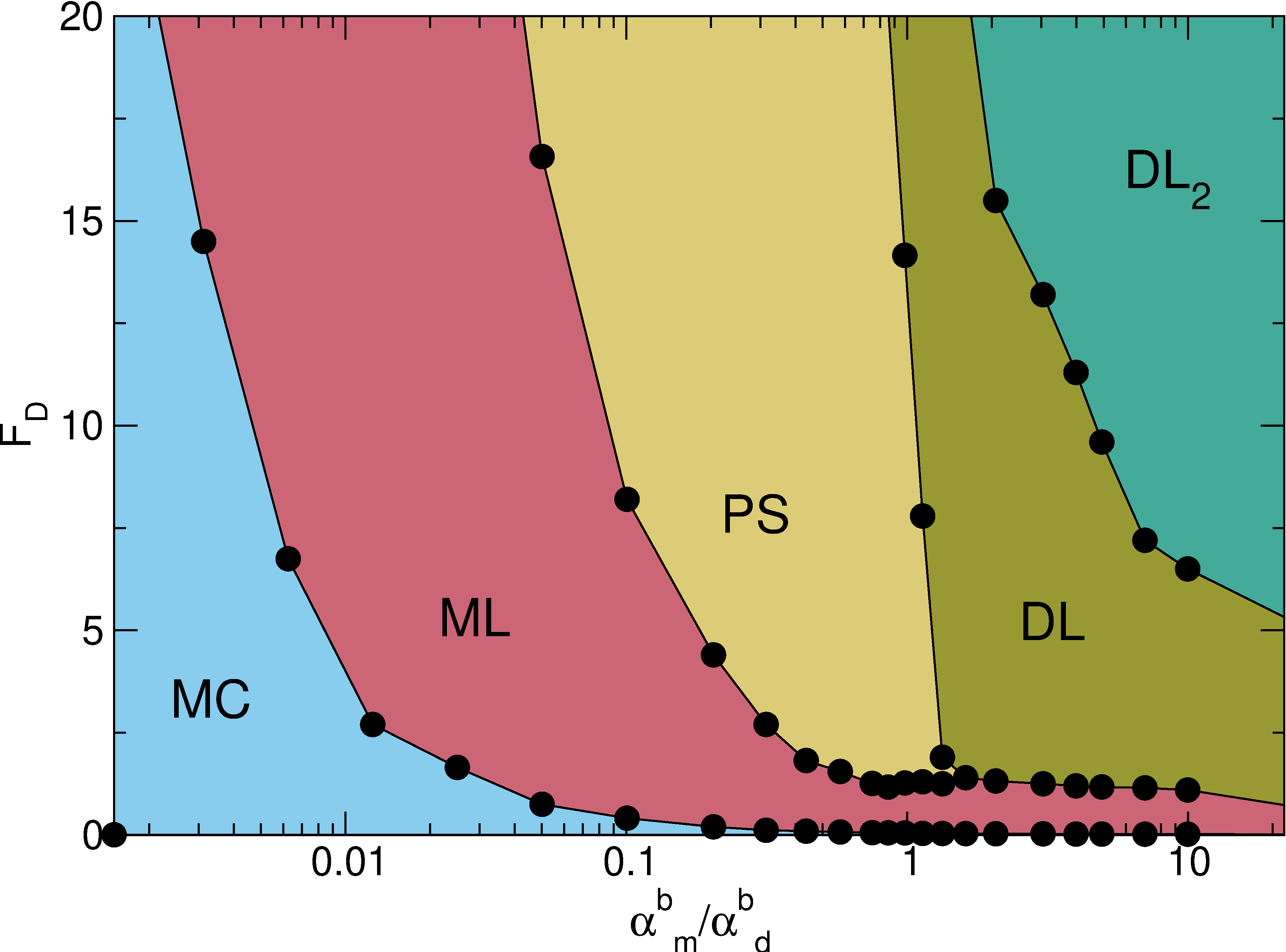
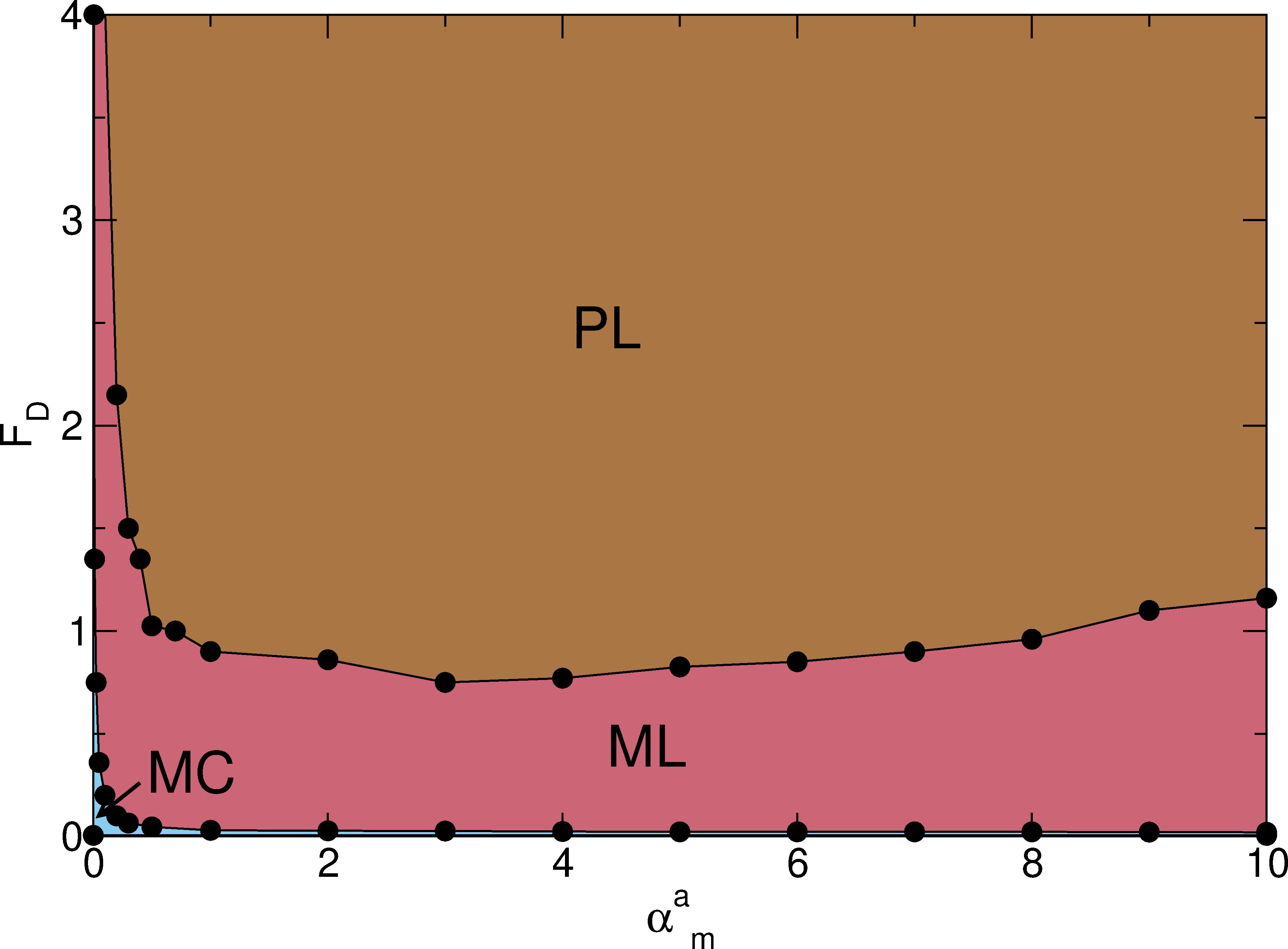
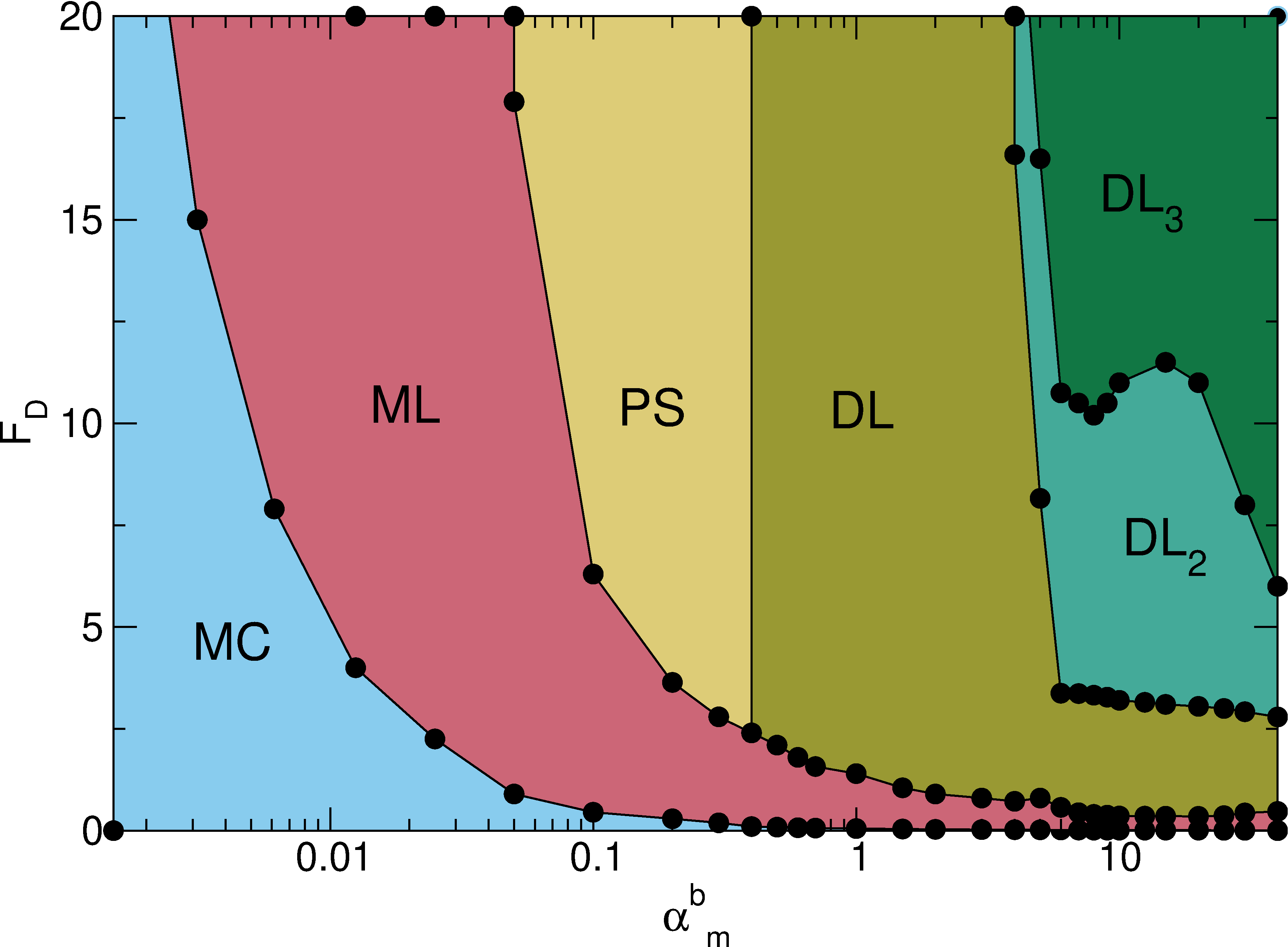
(b) Dynamic phase diagram as a function of FD vs system density n for samples with αad = αbd = 1.0, αam = 0, and αbm = 0.3, 
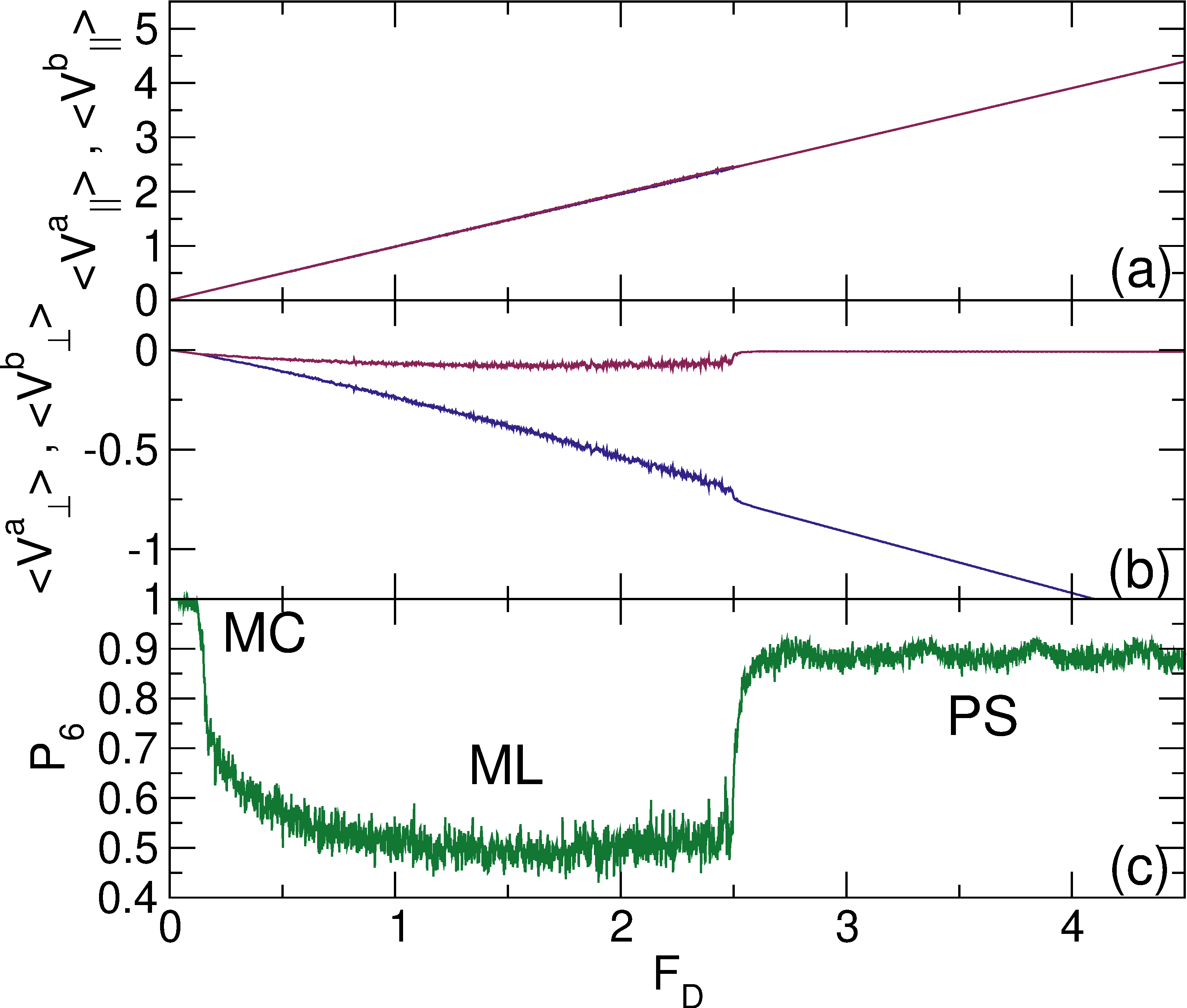
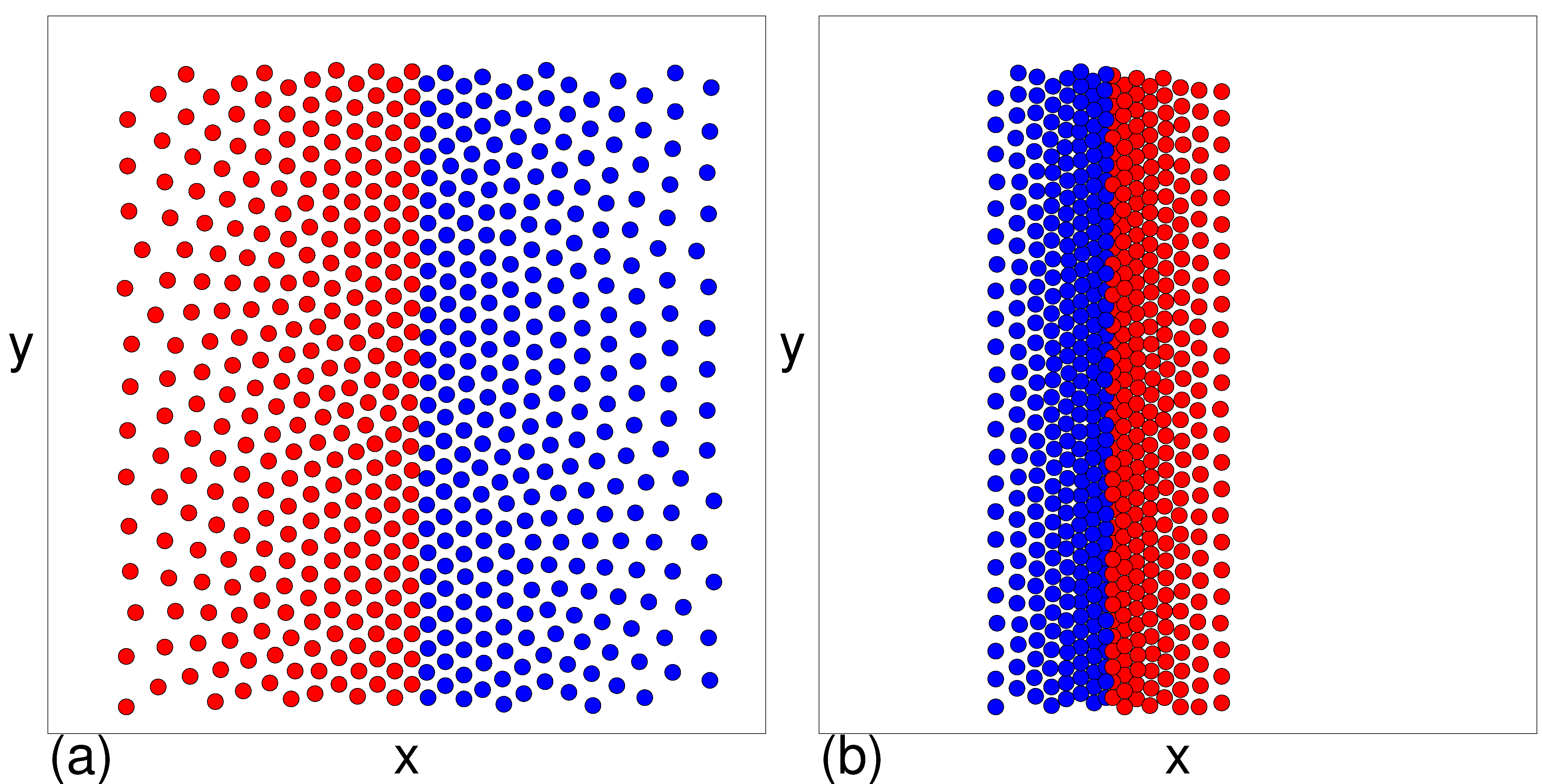
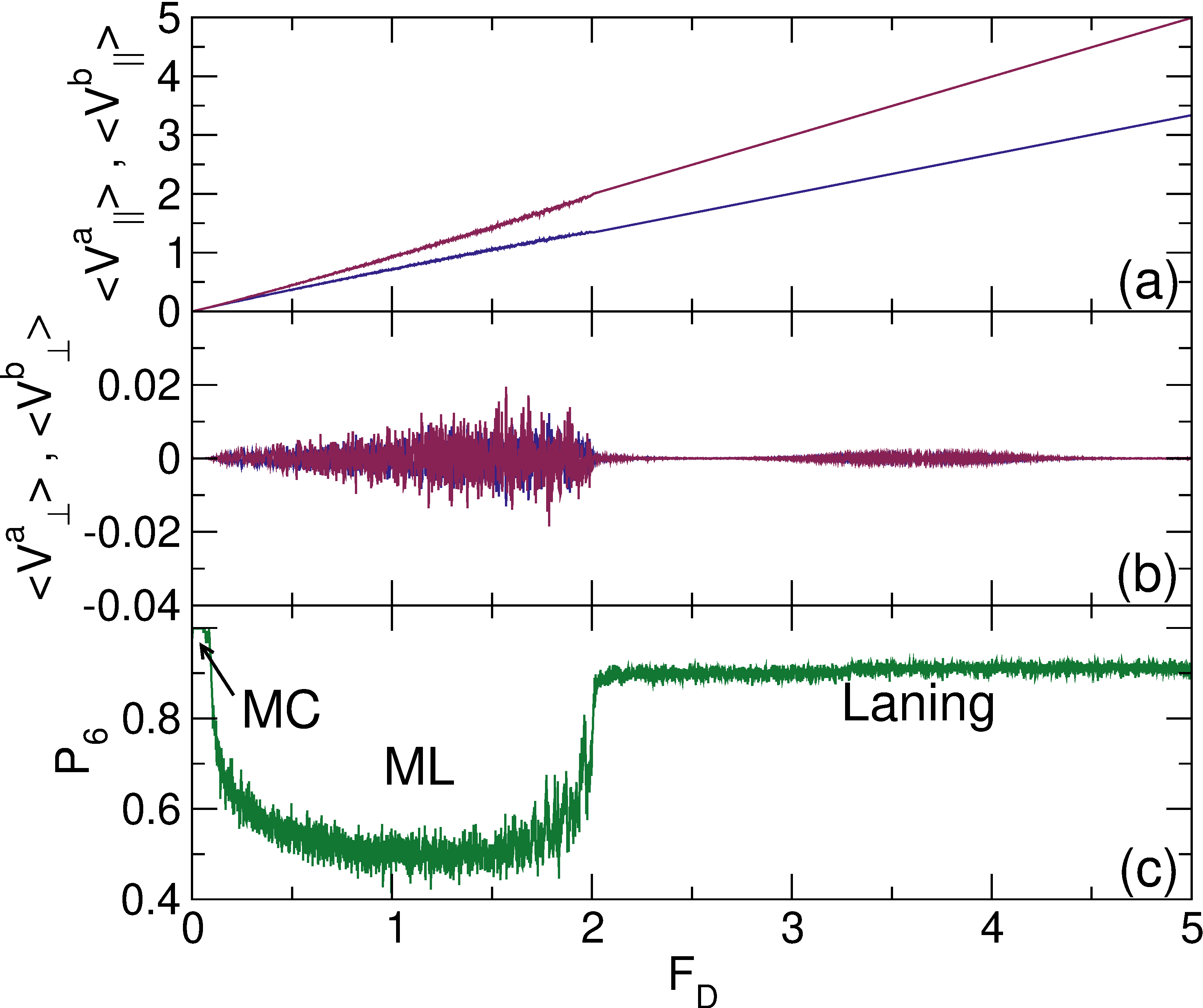
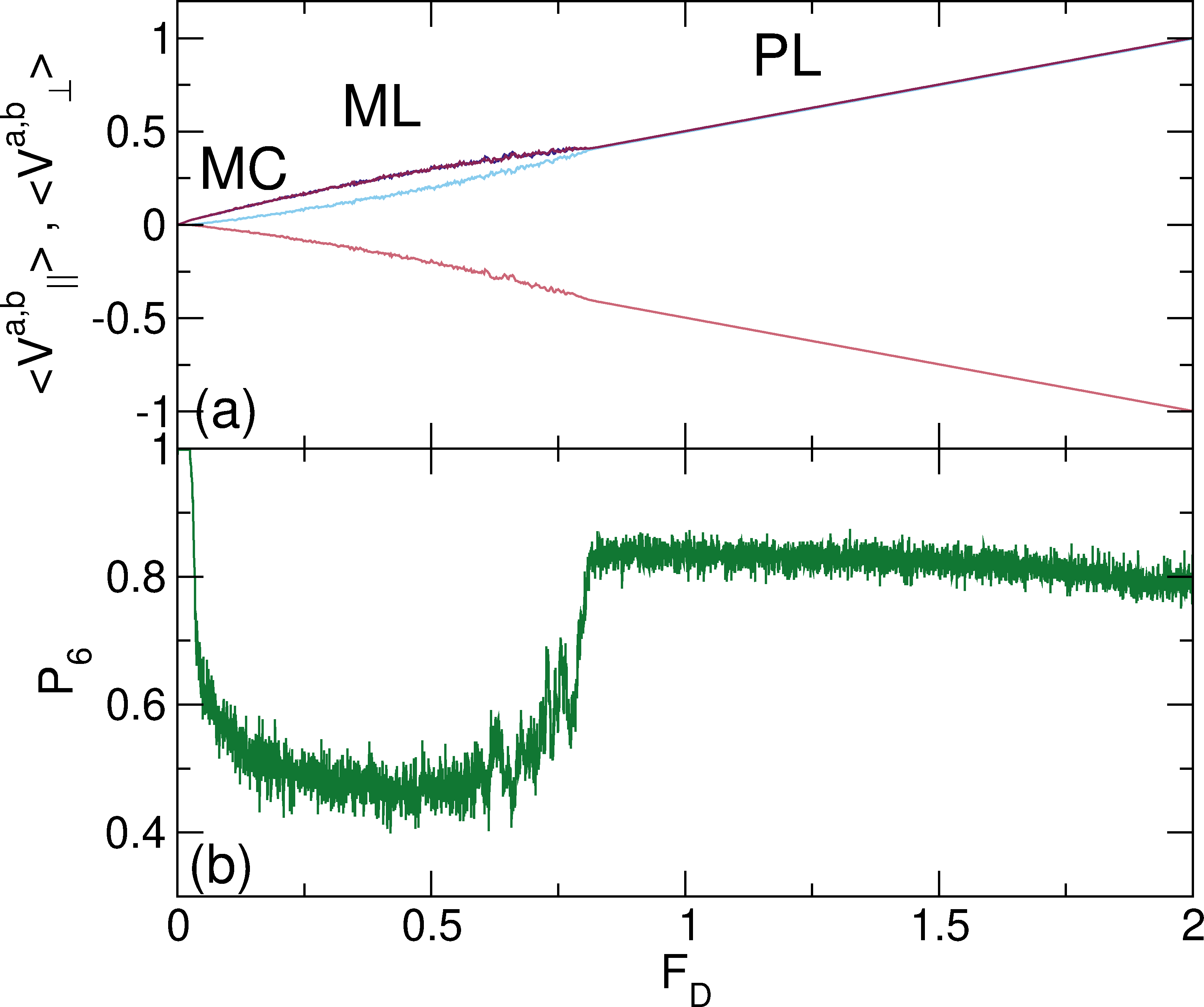
showing that the transitions between the moving crystal (MC), moving liquid (ML), and perpendicular stripe (PS) phases shift to higher values of FD with increasing density.
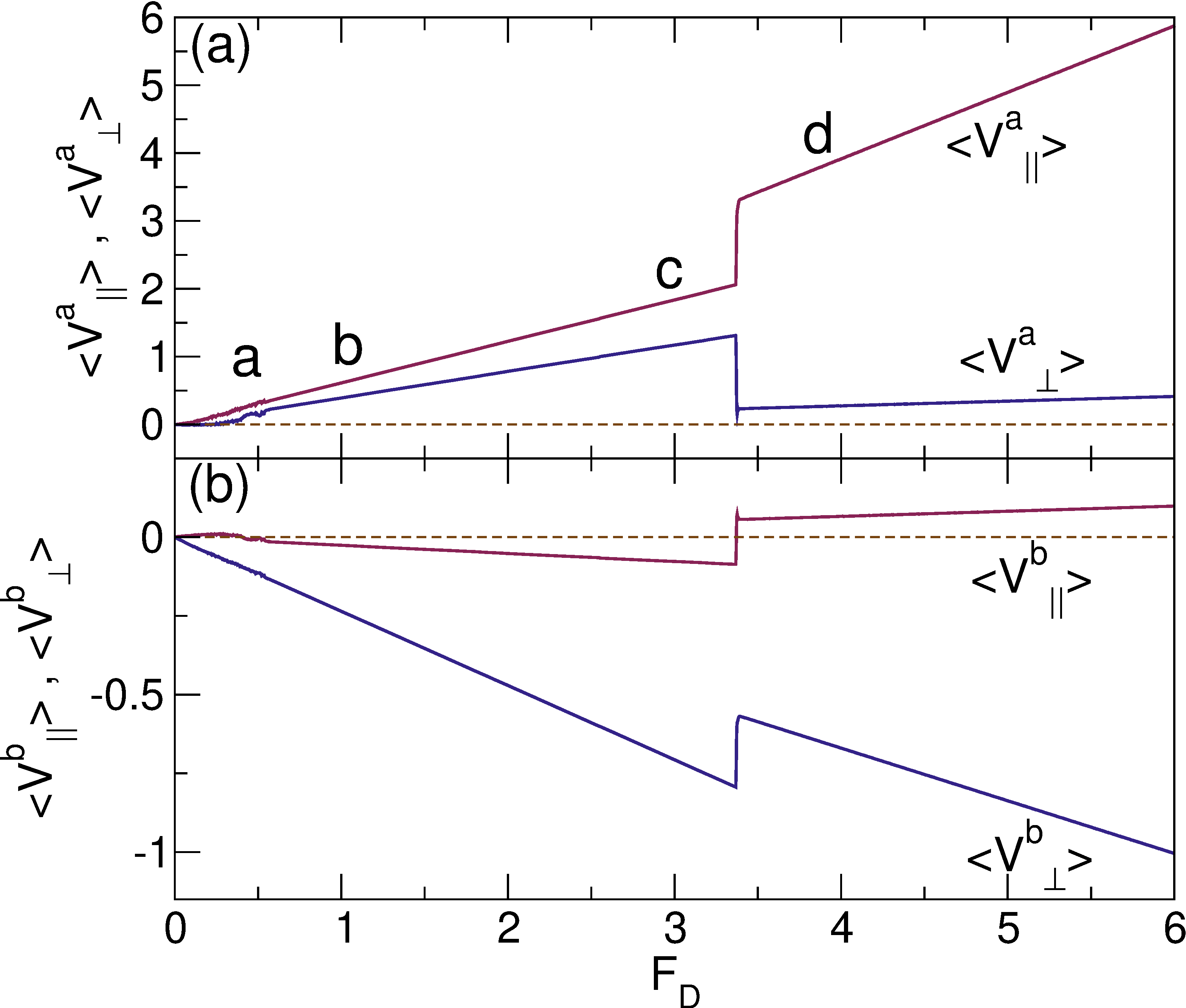
Fig24.png
Figure 24: Images of particle positions for species a (red) and b (blue) for a system with Nb/Na = 0.9, αad = αbd = 1.0, αam = 0, and αbm = 3.0. (a) A moving liquid phase. (b) A diagonal stripe state, showing that phase separation persists even when the ratio of the number of species a particles to species b particles is varied.
We have considered several other variables such as varied damping and varied Magnus ratios, and in general find the same phases described above with some minor variations. For example, in Fig. 23(a) we plot 〈Va||〉, 〈Vb||〉, 〈Va〉, and 〈Vb〉 versus FD for a system with αbd = 1.0, αad = 2.0, αam = 0.1, and αbm = −1.0, where we find a series of pronounced velocity jumps at the transitions into different DL and DL2 phases. The same generic phases persist when the system density is varied, as shown in the dynamic phase diagram as a function of FD and n in Fig. 23(b) for a system with αad = αbd = 1.0, αam = 0, and αbm = 0.3. As n increases, the transitions between the phases shift to higher values of FD. We observe a similar trend for higher values of αbm. We have also examined systems in which NaNb and find similar dynamic phases, as illustrated in Fig. 24(a,b) for a sample with Nb/Na = 0.9, αad = αbd = 1.0, αam = 0, and αbm = 3.0, where we show that in the ML phase, some species segregation occurs, while in the DL phase, thinner stripes appear. These results indicate that the general features we observe are robust for a wide range of parameters. We have tested systems with different densities and find that the same general phases occur; however, in denser systems, the increased skyrmion-skyrmion repulsion shifts the transition to the thinner stripe state up to larger values of the Magnus term and driving force. We have checked the effect of system size and find similar results in larger samples. In the single stripe state, a periodic array of stripes can form in larger samples that has a stripe spacing larger than the L=36 samples which are our focus here. In general the width and periodicity of the stripes depend on the values of the Mangus term, density, and drive. Increasing the Magnus term and drive tends to decrease the stripe width, while increasing the density tends to increase the stripe width.
In this work we have only considered bidisperse particles; however, it would also be interesting to study three or more particle species or even a continuum range of species with a Gaussian distribution of types. In such assemblies, it is possible that the system would generally form disordered or moving liquid phases; however, other new types of pattern formation could appear. We have only utilized particle-based simulations since these allow us to simulate a large number of particles over a wide range of parameters for long times, but it would also be interesting to perform continuum based simulations of multiple species or sizes of skyrmions to see whether similar effects arise when the internal degrees of freedom of the skyrmions are included. In our system, the Magnus term leads to the appearance of a skyrmion Hall angle, but there are recent studies which show that some skyrmion systems can exhibit motion that is more toroidal in addition to other types of complex dynamics [49,50]. It would be interesting to study such systems in the presence of multiple skyrmion species. Further effects could arise if the applied driving were ac rather than dc, since the multiple species could organize into different types of patterns under cyclic driving.

IX.  SUMMARY

We have examined a bidisperse system of particles with uniform pairwise interactions under dynamics that include both a damping term and a Magnus term. When both species have equal damping but only one species has a finite Magnus term, we find that the triangular lattice which forms under zero drive moves elastically at low drives with a Hall angle equal to the average Hall angle of the two species. At a critical drive, a Magnus induced disordering transition occurs in which each species moves with a different velocity in the direction perpendicular to the drive. The critical drive at which the disordering transition appears diverges as the Magnus term goes to zero. At higher drives, there is a transition to a perpendicular stripe or cluster state with both density and species phase separation. The stripes become more compressed as the drive or difference in Magnus terms increases, and another transition occurs to a density modulated diagonal laned state at even higher drives. The transitions are associated with pronounced jumps and locking of the transverse and longitudinal velocities of each species as well as changes in the global particle structures. We also find that multiple transitions can occur within the diagonal laned phase, each of which is accompanied by a reduction in both the number of particles in each row and the angle between the stripe and the driving direction, giving rise to a rich variety of different types of patterns. In some cases, one of the species can exhibit absolute negative mobility in which the particles move in the direction opposite to that of the applied drive due to the Magnus-induced rotation of the interaction forces between the two particle species. When both species have different damping terms but zero Magnus terms, we find dynamic phases that are very similar to those observed for oppositely driven Yukawa particles, which form uniform laned states. For equal damping terms and Magnus terms that are equal in magnitude but opposite in sign, uniform density states appear containing lanes that are perpendicular to the applied drive. We show that the diagonal laned and density modulated states are robust for a wide range of parameters and densities, and should be generic features of systems with dispersity in the Magnus force. We discuss the relation between our results and studies of skyrmion systems with dispersion in the Magnus force, where we predict that a disordering transition should occur as a function of increasing drive, and that a variety of clustered and pattern forming states could be observed. Similar effects may arise in soft matter systems containing Magnus terms, such as spinning magnetic particles in solution.

ACKNOWLEDGMENTS

This work was carried out under the auspices of the NNSA of the U.S. DoE at LANL under Contract No. DE-AC52-06NA25396.

References

[1]
D.S. Fisher, Collective transport in random media: From superconductors to earthquakes. Phys. Rep. 301, 113 (1998).
[2]
C. Reichhardt and C. J. Olson Reichhardt, Depinning and nonequilibrium dynamic phases of particle assemblies driven over random and ordered substrates: A review, Rep. Prog. Phys. 80, 026501 (2017).
[3]
S. Bhattacharya and M. J. Higgins, Dynamics of a Disordered Flux Line Lattice, Phys. Rev. Lett. 70, 2617 (1993).
[4]
C. J. Olson, C. Reichhardt, and F. Nori, Nonequilibrium Dynamic Phase Diagram for Vortex Lattices, Phys. Rev. Lett. 81, 3757 (1998).
[5]
A. Pertsinidis and X. S. Ling, Statics and Dynamics of 2D Colloidal Crystals in a Random Pinning Potential, Phys. Rev. Lett. 100, 028303 (2008).
[6]
P. Tierno, Depinning and Collective Dynamics of Magnetically Driven Colloidal Monolayers, Phys. Rev. Lett. 109, 198304 (2012).
[7]
T. Bohlein, J. Mikhael, and C. Bechinger, Observation of kinks and antikinks in colloidal monolayers driven across ordered surfaces, Nature Mater. 11, 126 (2012).
[8]
A. Vanossi, N. Manini, M. Urbakh, S. Zapperi, and E. Tosatti, Modeling friction: From nanoscale to mesoscale, Rev. Mod. Phys. 85, 529 (2013).
[9]
B.J. Ackerson and N.A. Clark, Shear-induced melting, Phys Rev Lett 46,123 (1981).
[10]
A. Imhof, A. van Blaaderen, and J.K.G. Dhont, Shear melting of colloidal crystals of charged spheares studied with rheology and polarizing microscopy, Langmuir 10, 3477 (1994).
[11]
R. Blaak, S. Auer, D. Frenkel, and H. Löwen, Crystal nucleation of colloidal suspensions under shear, Phys. Rev. Lett. 93, 068303 (2004).
[12]
I. Cohen, B. Davidovitch, A.B. Schofield, M.P. Brenner, and D.A. Weitz, Slip, yield and bands in colloidal crystals under oscillatory shear, Phys. Rev. Lett. 97, 215502 (2006).
[13]
Y.L. Wu, D. Derks, A. van Blaaderen, and A. Imhof, Melting and crystallization of colloidal hard-sphere suspensions under shear, Proc. Natl. Acad. Sci. (USA) 106, 10564 (2009).
[14]
M. R. Sadr-Lahijany, P. Ray, and H. E. Stanley, Dispersity-Driven Melting Transition in Two-Dimensional Solids, Phys. Rev. Lett. 79, 3206 (1997).
[15]
T. Hamanaka and A. Onuki, Transitions among crystal, glass, and liquid in a binary mixture with changing particle-size ratio and temperature, Phys. Rev. E 74, 011506 (2006)
[16]
C. Reichhardt and C. J. Olson Reichhardt, Disordering transitions and peak effect in polydisperse particle systems, Phys. Rev. E 77, 041401 (2008).
[17]
B. Schmittmann and R. K. P. Zia, Driven diffusive systems: An introduction and recent developments, Phys. Rep. 301, 45 (1998).
[18]
D. Helbing, I. J. Farkas, and T. Vicsek, Freezing by Heating in a Driven Mesoscopic System, Phys. Rev. Lett. 84, 1240 (2000).
[19]
J. Dzubiella, G. P. Hoffmann, and H. Löwen, Lane formation in colloidal mixtures driven by an external field, Phys. Rev. E 65, 021402 (2002).
[20]
R. R. Netz, Conduction and diffusion in two-dimensional electrolytes, Europhys. Lett. 63, 606 (2003).
[21]
M. Ikeda, H. Wada, and H. Hayakawa, Instabilities and turbulence-like dynamics in an oppositely driven binary particle mixture, EPL 99, 68005 (2012).
[22]
C. W. Wächtler, F. Kogler, and S. H. L. Klapp, Lane formation in a driven attractive fluid, Phys. Rev. E 94, 052603 (2016).
[23]
K. Ikeda and K. Kim, Lane Formation Dynamics of Oppositely Self-Driven Binary Particles: Effects of Density and Finite System Size, J. Phys. Soc. Jpn. 86, 044004 (2017).
[24]
A. Poncet, O. Bénichou, V. Démery, and G. Oshanin, Universal Long Ranged Correlations in Driven Binary Mixtures, Phys. Rev. Lett. 118, 118002 (2017).
[25]
N. Bain and D. Bartolo, Critical mingling and universal correlations in model binary active liquids, Nat. Commun. 8, 15969 (2017).
[26]
C. Reichhardt, J. Thibault, S. Papanikolaou, and C. J. O. Reichhardt, Laning and clustering transitions in driven binary active matter systems, Phys. Rev. E 98, 022603 (2018).
[27]
C. Reichhardt and C. J. O. Reichhardt, Velocity force curves, laning, and jamming for oppositely driven disk systems, Soft Matter 14, 490 (2018).
[28]
T. Vissers, A. van Blaaderen, and A. Imhof, Band Formation in Mixtures of Oppositely Charged Colloids Driven by an ac Electric Field, Phys. Rev. Lett. 106, 228303 (2011).
[29]
T. Vissers, A. Wysocki, M. Rex, H. Lowen, C. P. Royall, A. Imhof, and A. van Blaaderen, Lane formation in driven mixtures of oppositely charged colloids, Soft Matter 7, 2352 (2011).
[30]
K. R. Sütterlin, A. Wysocki, A. V. Ivlev, C. Räth, H. M. Thomas, M. Rubin-Zuzic, W. J. Goedheer, V. E. Fortov, A. M. Lipaev, V. I. Molotkov, O. F. Petrov, G. E. Morfill, and H. Löwen, Dynamics of Lane Formation in Driven Binary Complex Plasmas, Phys. Rev. Lett. 102, 085003 (2009).
[31]
C.-R. Du, K. R. Sütterlin, A. V. Ivlev, H. M. Thomas, and G. E. Morfill, Model experiment for studying lane formation in binary complex plasmas, EPL 99, 45001 (2012).
[32]
S. Mühlbauer, B. Binz, F. Jonietz, C. Pfleiderer, A. Rosch, A. Neubauer, R. Georgii, and P. Böni, Skyrmion lattice in a chiral magnet, Science 323, 915 (2009).
[33]
X. Z. Yu, Y. Onose, N. Kanazawa, J. H. Park, J. H. Han, Y. Matsui, N. Nagaosa, and Y. Tokura, Real-space observation of a two-dimensional skyrmion crystal, Nature (London) 465, 901 (2010).
[34]
N. Nagaosa and Y. Tokura, Topological properties and dynamics of magnetic skyrmions, Nat. Nanotechnol. 8, 899 (2013).
[35]
T. Schulz, R. Ritz, A. Bauer, M. Halder, M. Wagner, C. Franz, C. Pfleiderer, K. Everschor, M. Garst, and A. Rosch, Emergent electrodynamics of skyrmions in a chiral magnet, Nat. Phys. 8, 301 (2012).
[36]
J. Iwasaki, M. Mochizuki, and N. Nagaosa, Universal current-velocity relation of skyrmion motion in chiral magnets, Nat. Commun. 4, 1463 (2013).
[37]
S.-Z. Lin, C. Reichhardt, C.D. Batista, and A. Saxena, Particle model for skyrmions in metallic chiral magnets: Dynamics, pinning, and creep, Phys. Rev. B 87, 214419 (2013).
[38]
W. Jiang, P. Upadhyaya, W. Zhang, G. Yu, M. B. Jungfleisch, F. Y. Fradin, J. E. Pearson, Y. Tserkovnyak, K. L. Wang, O. Heinonen, S. G. E. te Velthuis, and A. Hoffmann, Blowing magnetic skyrmion bubbles, Science 349, 283 (2015).
[39]
S. Woo, K. Litzius, B. Kruger, M. Y. Im, L. Caretta, K. Richter, M. Mann, A. Krone, R. M. Reeve, M. Weigand, P. Agrawal, I. Lemesh, M. A. Mawass, P. Fischer, M. Klaui, and G. R. S. D. Beach, Observation of room temperature magnetic skyrmions and their current-driven dynamics in ultrathin Co films, Nat. Mater. 15, 501 (2016).
[40]
D. Liang, J. P. DeGrave, M. J. Stolt, Y. Tokura, and S. Jin, Current-driven dynamics of skyrmions stabilized in MnSi nanowires revealed by topological Hall effect, Nat. Commun. 6, 8217 (2015).
[41]
C. Reichhardt, D. Ray, and C. J. Olson Reichhardt, Collective Transport Properties of Driven Skyrmions with Random Disorder, Phys. Rev. Lett. 114, 217202 (2015).
[42]
C. Reichhardt, D. Ray, and C. J. Olson Reichhardt, Quantized transport for a skyrmion moving on a two-dimensional periodic substrate, Phys. Rev. B 91, 104426 (2015).
[43]
W. Jiang, X. Zhang, G. Yu, W. Zhang, X. Wang, M. B. Jungfleisch, J. E. Pearson, X. Cheng, O. Heinonen, K. L. Wang, Y. Zhou, A. Hoffmann, and S. G. E. te Velthuis, Direct observation of the skyrmion Hall effect, Nat. Phys. 13, 162 (2017).
[44]
K. Litzius, I. Lemesh, B. Krüger, P. Bassirian, L. Caretta, K. Richter, F. Büttner, K. Sato, O. A. Tretiakov, J. Förster, R. M. Reeve, M. Weigand, I. Bykova, H. Stoll, G. Schütz, G. S. D. Beach, and M. Kläui, Skyrmion Hall effect revealed by direct time-resolved x-ray microscopy, Nat. Phys. 13, 170 (2017).
[45]
W. Legrand, D. Maccariello, N. Reyren, K. Garcia, C. Moutafis, C. Moreau-Luchaire, S. Collin, K. Bouzehouane, V. Cros, and A. Fert, Room-temperature current-induced generation and motion of sub-100 nm skyrmions, Nano. Lett. 17, 2703 (2017).
[46]
A. Soumyanarayanan, M. Raju, A.L. Gonzalez Oyarce, A.K.C. Tan, M.-Y. Im, A.P. Petrovic, P. Ho, K.H. Khoo, M. Tran, C.K. Gan, F. Ernult, and C. Panagopoulos, Tunable room-temperature magnetic skyrmions in Ir/Fe/Co/Pt multilayers, Nat. Mater. 16, 898 (2017).
[47]
A.K. Nayak, V. Kumar, T. Ma, P. Werner, E. Pippel, R. Sahoo, F. Damay, U.K. Rössler, C. Felser, and S.S.P. Parkin, Magnetic antiskyrmions above room temperature in tetragonal Heusler materials, Nature (London) 548, 561 (2017).
[48]
K. Karube, J.S. White, D. Morikawa, C.D. Dewhurst, R. Cubitt, A. Kikkawa, X. Yu, Y. Tokunaga, T. Arima, H.M. Rønnow, Y. Tokura, and Y. Taguchi, Disordered skyrmion phase stabilized by magnetic frustration in a chiral magnet, Sci. Adv. 4, EAAR7043 (2018).
[49]
A.A. Kovalev and S. Sandhoefner, Skyrmions and Antiskyrmions in Quasi-Two-Dimensional Magnets, Front. Phys. 6, 98 (2018).
[50]
U. Ritzmann, S. von Malottki, J.-V. Kim, S. Heinze, J. Sinova and B. Dupe, Trochoidal motion and pair generation in skyrmion and antiskyrmion dynamics under spin–orbit torques, Nature Electron. 1, 451 (2018).
[51]
S.A. Díaz, C. J. O. Reichhardt, D. P. Arovas, A. Saxena, and C. Reichhardt, Fluctuations and noise signatures of driven magnetic skyrmions, Phys. Rev. B 96, 085106 (2017).
[52]
W. Koshibae and N. Nagaosa, Theory of current-driven skyrmions in disordered magnets, Sci. Rep. 8, 6328 (2018).
[53]
F. Pardo, F. de la Cruz, P. L. Gammel, E. Bucher, and D. J. Bishop, Observation of smectic and moving-Bragg-glass phases in flowing vortex lattices, Nature (London) 396, 348 (1998).
[54]
C. Reichhardt and C. J. O. Reichhardt, Nonlinear Transport, Dynamic Ordering, and Clustering for Driven Skyrmions on Random Pinning, arXiv:1808.08214.
[55]
S. I. Denisov and B. O. Pedchenko, Drift of suspended ferromagnetic particles due to the Magnus effect, J. Appl. Phys. 121, 043912 (2017).
[56]
S. I. Denisov, B. O. Pedchenko, O. V. Kvasnina, and E. S. Denisova, Exactly solvable model for drift of suspended ferromagnetic particles induced by the Magnus force, J. Mag. Mag. Mater. 443, 89 (2017).
[57]
S. I. Denisov, T. V. Lyutyy, V. V. Reva, and A. S. Yermolenko, Temperature effects on drift of suspended single-domain particles induced by the Magnus force, Phys. Rev. E 97, 032608 (2018).
[58]
G. M. Whitesides and B. Grzybowski, Self-assembly at all scales, Science 295, 2418 (2002).
[59]
Y. Goto and H. Tanaka, Purely hydrodynamic ordering of rotating disks at a finite Reynolds number, Nat. Commun. 6, 5994 (2015).
[60]
B. L. Brown, U. C. Täuber, and M. Pleimling, Effect of the Magnus force on skyrmion relaxation dynamics, Phys. Rev. B 97, 020405(R) (2018).
[61]
C. Reichhardt and C. J. Olson Reichhardt, Noise fluctuations and drive dependence of the skyrmion Hall effect in disordered systems, New J. Phys. 18, 095005 (2016).
[62]
F. Rothen and P. Pieranski, Mechanical equilibrium of conformal crystals, Phys. Rev. E 53, 2828 (1996).
[63]
Y. L. Wang, M. L. Latimer, Z. L. Xiao, R. Divan, L. E. Ocola, G. W. Crabtree, and W. K. Kwok, Enhancing the critical current of a superconducting film in a wide range of magnetic fields with a conformal array of nanoscale holes, Phys. Rev. B 87, 220501 (2013).
[64]
S. Guénon, Y. J. Rosen, A. C. Basaran, and I. K. Schuller, Highly effective superconducting vortex pinning in conformal crystals, Appl. Phys. Lett. 102, 252602 (2013).
[65]
D. Ray, C. Reichhardt, and C. J. Olson Reichhardt Pinning, ordering, and dynamics of vortices in conformal crystal and gradient pinning arrays, Phys. Rev. B 90, 094502 (2014).
[66]
R. M. Menezes and C. C. de Souza Silva, Conformal Vortex Crystals, Sci. Rep. 7, 12766 (2017).
[67]
V. Soni, L. R. Gómez, and W. T. M. Irvine, Emergent Geometry of Inhomogeneous Planar Crystals, Phys. Rev. X 8, 011039 (2018).
[68]
G. A. Cecchi and M. O. Magnasco, Negative Resistance and Rectification in Brownian Transport, Phys. Rev. Lett. 76, 1968 (1996).
[69]
R. Eichhorn, P. Reimann, and P. Hänggi, Paradoxical motion of a single Brownian particle: Absolute negative mobility, Phys. Rev. E 66, 066132 (2002).
[70]
C. Reichhardt and C. J. Olson Reichhardt, Absolute transverse mobility and ratchet effect on periodic two-dimensional symmetric substrates, Phys. Rev. E 68, 046102 (2003).
[71]
A. Ros, R. Eichhorn, J. Regtmeier, T. T. Duong, P. Reimann and D. Anselmetti, Absolute negative particle mobility, Nature (London) 436, 928 (2005).
[72]
C. Reichhardt and C. J. Olson Reichhardt, Shapiro spikes and negative mobility for skyrmion motion on quasi-one-dimensional periodic substrates, Phys. Rev. B 95, 014412 (2017).


File translated from TEX by TTHgold, version 4.00.
Back to Home