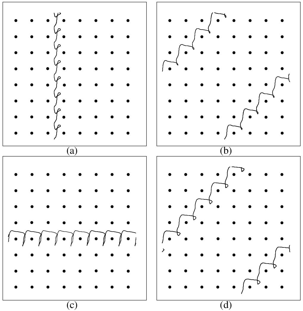
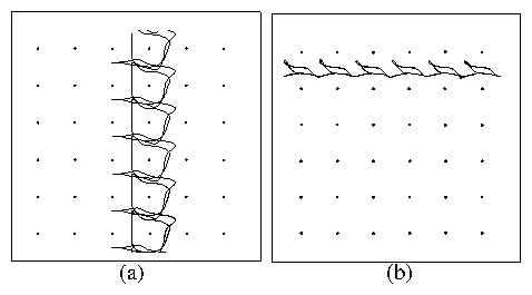
 Figure 8:
The particle trajectories
(black line) for a fixed time interval
and fDC = 0.0
for motion in a 2D periodic substrate with potential maxima
located at the black dots.
(a) A ratchet effect due to the breaking of a reflection symmetry.
The particle moves in the negative y-direction when
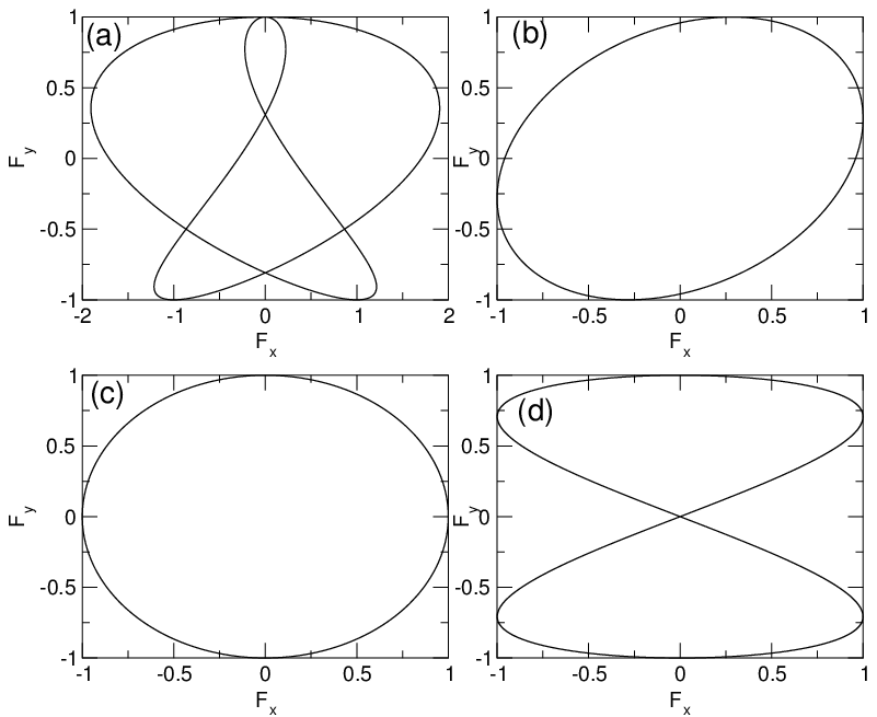
driven with the ac drive shown in
Fig. 7(a),
fAC = Asin(ωAt)∧x + Asin(1.5ωAt)∧x − Bcos(1.5ωBt)∧y,
A/B=1, ωA/ωB=1.
(b) A ratchet effect produced by the addition of a phase shift.
The particle moves in the positive x-direction when
driven with the ac drive shown in Fig. 7(b),
fAC = Asin(ωA t + δ)∧x− Bcos(ωBt),
δ = 0.287, A/B=1, and ωA/ωB=1.
Figure 8:
The particle trajectories
(black line) for a fixed time interval
and fDC = 0.0
for motion in a 2D periodic substrate with potential maxima
located at the black dots.
(a) A ratchet effect due to the breaking of a reflection symmetry.
The particle moves in the negative y-direction when
driven with the ac drive shown in
Fig. 7(a),
fAC = Asin(ωAt)∧x + Asin(1.5ωAt)∧x − Bcos(1.5ωBt)∧y,
A/B=1, ωA/ωB=1.
(b) A ratchet effect produced by the addition of a phase shift.
The particle moves in the positive x-direction when
driven with the ac drive shown in Fig. 7(b),
fAC = Asin(ωA t + δ)∧x− Bcos(ωBt),
δ = 0.287, A/B=1, and ωA/ωB=1.
|