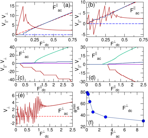
Physical Review B 95, 014412 (2017)

Shapiro Spikes and Negative Mobility for Skyrmion Motion on Quasi-One Dimensional Periodic Substrates

C. Reichhardt and C. J. Olson Reichhardt

Theoretical Division and Center for Nonlinear Studies, Los Alamos National Laboratory, Los Alamos, New Mexico 87545, USA

(Received 29 June 2016; revised manuscript received 16 November 2016; published 12 January 2017)

Using a simple numerical model of skyrmions in a two-dimensional system interacting with a quasi-one dimensional periodic substrate under combined dc and ac drives where the dc drive is applied perpendicular to the substrate periodicity, we show that a rich variety of novel phase locking dynamics can occur due to the influence of the Magnus term on the skyrmion dynamics. Instead of Shapiro steps, the velocity response in the direction of the dc drive exhibits a series of spikes, including extended dc drive intervals over which the skyrmions move in the direction opposite to the dc drive, producing negative mobility. There are also specific dc drive values at which the skyrmions move exactly perpendicular to the dc drive direction, giving a condition of absolute transverse mobility.
I. INTRODUCTION
II. SIMULATION
III. RESULTS AND DISCUSSION
IV. SUMMARY
REFERENCES

I.  INTRODUCTION

When an overdamped particle is driven by a combined dc and ac drive over a periodic substrate, a series of steps, called Shapiro steps [1], appear in the velocity response over fixed dc drive intervals due to phase locking between the ac driving frequency and the oscillatory frequency of the particle motion induced by the substrate periodicity. Phase locking of this type occurs for dc plus ac driven Josephson junction arrays [2], sliding charge density waves [3], vortices in type-II superconductors [4,5,6] or colloids [7] moving over periodic pinning arrays, frictional systems [8], and numerous other nonlinear systems in which there are two coupled competing frequencies [9,10,11]. In a two dimensional (2D) overdamped system with a quasi-one-dimensional (q1D) substrate, Shapiro steps only occur when the dc and ac drives are both applied parallel to the substrate periodicity direction, since the pinning does not induce a periodic modulation of the particle motion for perpendicular driving. In some systems, additional non-dissipative terms can be relevant to the particle dynamics, such as a Magnus force which generates a particle velocity component that is perpendicular to the net applied force on the particle. Magnus effects are known to be important for skyrmions in chiral magnets, where the ratio of the Magnus term to the damping term can be ten or higher [12,13,14,15,16,17]. Skyrmions can be set into motion by an applied spin-polarized current, and the Magnus term has been shown to strongly affect the interaction of the moving skyrmions with pinning sites, leading to reduced depinning thresholds [14,15,16,18,19], a drive dependent skyrmion Hall angle [19,20,21,22], and skyrmion speed up effects [20,21].
Recent studies of skyrmions driven over a periodic q1D substrate by a dc drive that is parallel to the substrate periodicity direction combined with a perpendicular ac drive showed that a new class of Magnus-induced Shapiro steps arises due to an effective coupling by the Magnus term of the perpendicular and parallel particle motion, whereas in the overdamped limit no Shapiro steps occur for this drive configuration [23]. Here we examine skyrmions confined to a 2D plane containing a q1D periodic substrate and moving under the influence of a dc drive applied perpendicular to the substrate periodicity direction along with a parallel or perpendicular ac drive, and we find that a rich variety of dynamical phases can occur. Instead of Shapiro steps, the particle velocity response in the dc drive direction exhibits what we call Shapiro spikes where the slope of the velocity-force curve locks to a constant value over a range of dc driving forces. One of the most remarkable features of this system is that there are also a series of extended dc drive regions where the particle motion is in the direction opposite to the dc drive, known as negative mobility [24,25,26]. It is even possible for the particle motion at some drives to be exactly perpendicular to the dc drive direction, creating a condition of absolute transverse mobility [27]. Negative mobility effects have been observed in overdamped systems but generally require more complicated substrates, thermal fluctuations, many-particle collective effects, or the application of multiple ac drives, whereas in the skyrmion system, negative mobility arises for a much simpler set of conditions. We map the evolution of the dynamic phases as a function of ac drive amplitude and the ratio of the Magnus to the damping term. In addition to their interest as signatures of a new dynamical system, these results could also provide a new way to precisely control the direction of motion of skyrmions in order to realize skyrmion-based memory or logic devices [28].

II.  SIMULATION

We model a 2D system with periodic boundary conditions in the x and y directions containing a q1D substrate and a skyrmion treated with a particle-based model that has previously been used to examine driven skyrmion motion in random[18,19], 2D periodic [21], and 1D periodic substrates [23,29]. The skyrmion dynamics are determined using the following equation of motion:
αd vi + αm
^
z
 
×vi = Fspi + Fdc + Fac ,
(1)
where the skyrmion velocity is vi = d ri/dt. On the left hand side, αd gives the strength of the damping term, which aligns the skyrmion velocity in the direction of the net external forces, while αm is the Magnus term, which rotates the velocity in the direction perpendicular to the net external forces. For varied ratios of αmd we impose the constraint αd2 + αm2 = 1. The force from the substrate is Fspi = ∇U(xi)x where U(x) = Uocos(2πx/a) and a is the substrate lattice constant. The substrate strength is defined to be Ap ≡ 2πU0/a. Unless otherwise noted, the dc drive Fdc=Fdcy is applied perpendicular to the substrate periodicity direction, while the ac driving force Fac=Fac||x or Fac=Facy is applied either parallel or perpendicular to the substrate periodicity direction, respectively. We characterize the system by measuring the velocity response V||=2π〈Vx〉/ωa parallel to the substrate periodicity and V=2π〈Vy〉/ωa perpendicular to the substrate periodicity, so that on a Shapiro step the velocity is integer valued with V||=n or V=n, allowing us to identify the step number n.
Fig1.png
Figure 1: (a) The average skyrmion velocity V|| (blue) and V (red) vs Fdc for a system with pinning strength Ap = 1.0 and perpendicular ac drive Fac = 0.325 at different ratios αmd of the Magnus to dissipative terms. Solid lines: αmd = 9.96; dashed lines: αmd=0. For αmd=9.96, there are Shapiro steps in V|| and spikes in V, along with intervals in which V < 0. (b) The same for αmd=3.219 (solid lines) and αmd=0 (dashed lines).

III.  RESULTS AND DISCUSSION

In Fig. 1(a) we plot V|| and V versus Fdc for a system with Ap = 1.0, αmd = 9.96, and Fac = 0.325. The dashed lines show the average velocities in the overdamped limit of αmd = 0, where the particles simply slide along the y-direction with an Ohmic response and phase locking does not occur. When the Magnus term is finite, V|| shows a series of phase-locked Shapiro steps, while V shows a completely different response consisting of spike like features. On each phase-locked step in V||, the slope of V is constant. The most remarkable feature in V is that there are four extended intervals of Fdc over which V < 0, indicating that the particle is moving in the opposite direction to the applied dc drive, a phenomenon known as negative mobility [25,26]. On a given step, V can grow from negative values to positive values, passing through a point at which V|| is finite but V = 0, indicating that particle is moving exactly perpendicular to the applied dc drive in a phenomenon known as absolute transverse mobility [27]. At higher values of Fdc, the negative mobility regions are lost and the minimum value of V at the bottom of each spike increases with increasing Fdc. At the top of the V spikes, the particle velocity in the dc drive direction is higher than it would be in an overdamped system, which is an example of a pinning-induced speed up effect [20,21]. After each spike, V decreases with with increasing Fdc, which is an example of negative differential conductivity. In Fig. 1(b) we show that for αmd = 3.219, there are still spikes in V; however, the regions of negative mobility are lost. As αmd is further reduced, V gradually becomes smoother and approaches the dashed line, which indicates the response in the overdamped limit.
Fig2.png
Figure 2: Skyrmion location (dot) and trajectory (line) on a q1D periodic substrate potential for ac and dc drives both applied along the perpendicular or y direction for the system in Fig. 1(a) with αmd=9.96. The lighter regions indicate the locations of the substrate minima. (a) Fdc = 0.015 along the n = 0 step with V > 0 and V||=0 (Region I). (b) Fdc = 0.055, showing a phase locked region with negative mobility where V < 0 and V|| > 0 (Region II). (c) Fdc = 0.064815, a phase locked state where there is absolute transverse mobility with V = 0 and V|| > 0 (Region III). (d) Fdc = 0.085 along the n = 1 step, where V and V|| are both positive (Region I). (e) Fdc = 0.095, where there is a non-phase locked region with V > 0 and V|| > 0 (Region V). (f) Fdc=0.105, where there is a non-phase locked region with negative mobility (Region VI).
From the dynamics in Fig. 1(a) we define six different regimes for the particle motion. Region I is a phase locked state in which the particle moves in a periodic orbit with V > 0 and V|| ≥ 0. In Fig. 2(a) we show the Region I particle trajectory at Fdc = 0.015, corresponding to the n = 0 step where the particle orbit translates only along the y direction. Figure 2(d) illustrates the n=1 step at Fdc = 0.085, where the particle moves in a periodic orbit that translates in both the positive x and y directions. Region II is a phase locked state in which the particle moves in the direction opposite to the dc driving force with V < 0, as shown in Fig. 2(b) for Fdc = 0.055 on the n = 1 step where the periodic particle orbit translates in the positive x and negative y directions. In Region III, which is also phase locked, the particle exhibits absolute transverse mobility and moves strictly in the positive x-direction with V = 0, as shown in Fig. 2(c) at Fdc = 0.064815. This corresponds to a skyrmion Hall angle of θsk=90°. Region IV is a non-phase locked state in which V = 0 while V|| is positive. It occurs in the non-step regions where the particle does not follow a periodic orbit and does not translate along the y direction, such as near Fdc = 0.04 in Fig. 1(a). The absolute transverse mobility of Regions III and IV only occurs at specific values of Fdc where the V versus Fdc curve crosses zero in Fig. 1, while the other phases span extended intervals of the dc driving force. Region V is a non-phase locked state where V and V|| are both positive but the particle does not form a periodic orbit, as illustrated in Fig. 2(e) at Fdc = 0.095. Finally, Region VI is a non-phase locked state in which V < 0 and V|| > 0, as shown in Fig. 2(f) at Fdc = 0.105. We note that there can be smaller intervals outside of the integer phase locked steps over which the system can exhibit fractional phase locking, and that these fractional steps become more prominent for higher values of Fac.
To understand the Shapiro spike shape for V in Fig. 1, it is important to note that the substrate has no features, and therefore no fixed length scale, in the direction perpendicular to its periodicity. Instead, due to the Magnus-induced coupling between motion in the parallel and perpendicular directions, there is an emergent effective length scale aeff in the perpendicular direction corresponding to the y-direction width of the skyrmion trajectory. This emergent length scale changes linearly with increasing Fdc, producing a constant slope on each of the Shapiro spikes. The value of this slope increases with increasing αmd, as shown in Fig. 1.
Fig3.png
Figure 3: (a) V|| (blue) and V (red) vs Fdc for perpendicular dc driving and parallel ac driving at F||ac = 0.325. Solid lines: αmd=9.96; dashed lines: αmd=0. (b) The same for F||ac = 2.35, where there are intervals in which V < 0. (c) V|| (blue, green) and V (red, purple) vs F||dc for parallel dc driving and perpendicular ac driving at Fac = 0.325 for αmd = 9.96 (blue and red), showing Shapiro steps, and for αmd = 0 (green and purple), where no Shapiro steps occur. (d) V|| (blue, green) and V (red, purple) vs F||dc for parallel dc driving and parallel ac driving at F||ac = 0.325 for αmd = 9.96 (blue and red) and αmd = 0 (green and purple), showing Shapiro steps. (e) V vs Fdc at Ap=1.0 and Fac=1.0 for αmd = 9.96 (solid line) and αmd=0 (dashed line) showing that, compared to Fig. 1(a), there is an extended region of negative mobility. (f) The lowest value θskmin of the skyrmion Hall angle θsk = tan−1md) for which negative mobility appears for the system in Fig. 1 as a function of Fac. For sufficiently large Fac, negative mobility can be observed at skyrmion Hall angles well below θsk=60°.
We next consider the case of a perpendicular dc drive and a parallel ac drive, as shown in Fig. 3(a) where we plot V and V|| vs Fdc for a system with the same parameters as in Fig. 1(a) for F||ac = 0.325. Here, for αmd=9.96, there are still steps in V|| and spikes in V; however, V ≥ 0 for all Fdc. For the overdamped αmd=0 case, V|| = 0 and V increases linearly with increasing Fdc. In Fig. 3(b), for the same driving configuration at F||ac = 2.35, there are more steps in V as well as regions in which V < 0, similar to the perpendicular ac driving case in Fig. 1(a). This shows that it is possible to observe negative mobility and spike features in V whenever the dc drive is applied perpendicular to the substrate periodicity, regardless of the ac driving direction. The ac drive amplitudes at which the features appear are much lower for perpendicular ac driving than for parallel ac driving.
For comparison, Fig. 3(c) shows the results of applying a parallel dc drive Fdc|| and a perpendicular ac drive with Fac = 0.325 at αmd = 9.96. Here, phase locking steps are present but the spikes associated with negative mobility are not. In the overdamped case with αmd=0, V|| exhibits a finite depinning threshold but no Shapiro steps, while V=0 for all F||dc. In Fig. 3(d), both the ac and dc drives are parallel to the substrate periodicity with F||ac = 0.325. At αmd = 9.96, both V|| and V exhibit Shapiro steps, while in the overdamped limit with αmd=0, there are Shapiro steps in V|| but V = 0. This shows that in the overdamped limit, Shapiro steps occur only when both the ac and dc driving are applied parallel to the substrate periodicity direction.
The negative mobility for perpendicular dc driving arises due to the combination of the Magnus term and the skyrmion-pinning interactions. Under a finite Magnus term, the dc drive generates an x direction force Fx=Fdcsin(θsk) on the skyrmion, where θsk=tan−1md). In response, the substrate exerts an x direction force on the skyrmion that the Magnus term transforms into a y velocity component in the range Vy = ±Apsin(θsk). For certain intervals of Fdc, the −y portion of the ac driving cycle synchronizes with the time at which the pinning force generates a −y velocity component, resulting in a net negative value of V. Conversely, in other Fdc intervals the +y portion of the ac driving cycle synchronizes with the time at which the substrate generates a +y velocity component, producing a speed up effect with enhanced positive V. Somewhere between these two intervals, V = 0 and absolute transverse mobility occurs. All of these effects become stronger for higher ac amplitude and larger ratios of αmd. A similar argument can be made for ac driving in the x-direction; however, the ac amplitude must be larger by a factor of approximately αmd, such as shown in Fig. 3(b), for effects of the same magnitude to occur, since for a parallel ac drive the y-velocity component is multiplied by a factor of cos(θsk) instead of sin(θsk).
We define the quantity θskmin to be the smallest skyrmion Hall angle for which negative mobility can be observed. For Ap = 1.0 and Fac = 0.325, Fig. 1(b) shows that negative mobility disappears below αmd ≈ 3.2, giving θskmin = tan−1md)=74°. For a fixed Ap, as Fac increases, the number of Shapiro spikes increases and negative mobility appears over a larger range, as shown in Fig. 3(e) where we plot V versus Fdc at Ap = 1.0 and Fac = 1.0. Compared to the same system in Fig. 1(a) with Fac=0.325, there are many more regions of negative mobility, while at higher drives the Shapiro spikes vanish. In Fig. 3(f) we plot θskmin versus Fac for the system in Fig. 1(a), showing that θskmin can be well below 60° for sufficiently large ac drives, reaching a value of θskmin ≈ 30° corresponding to αmd = 0.577 for Fac values that are about ten times larger than the dc depinning threshold. For many materials such as MnSi, large intrinsic skyrmion Hall angles are expected; however, recent experiments for skyrmions in room temperature samples show a drive dependent θsk that ranges from θsk=0° at low dc drives to θsk=32° for large dc drives [22,31], while some calculations indicate that the intrinsic θsk could be near θsk=55° [31]. As shown in Fig. 1(b), the Shapiro spike phenomenon is much more robust than the negative mobility, and Shapiro spikes should be observable for even the smallest values of θsk, although the range of dc drives over which the spike features appear decreases with decreasing θsk.
Typical skyrmion velocities vs for MnSi range from vs=10−4 m/s [14] to 0.1 m/s [32], while in room temperature samples, vs=0.1 m/s [22] to 100 m/s [31]. The Shapiro spike and negative mobility effects should be visible for ac frequencies that are not so high that the skyrmions are unable to respond. For samples containing structures with a periodicity of a=200 nm, this maximum frequency is ν = a/vs, giving ν = 103 to 105 Hz in MnSi samples (KHz range) and ν = 106 to 107 Hz in room temperature samples (MHz range), indicating that Shapiro spikes should be visible well within experimentally accessible frequency ranges.
Fig4.png
Figure 4: (a) Dynamic phase diagram for Fdc vs Fac showing the locations of the n = 0, 1, and 2 steps (outlined in black) for αmd = 9.96. Green: phase locked regions with V > 0; white: unlocked regions with V > 0; orange: locked or unlocked regions with V < 0. Along the red lines, V = 0 and V|| > 0. (b) Dynamic phase diagram for Fdc vs αmd at Fac=0.325. Colors are the same as in panel (a).
In Fig. 4(a) we plot the evolution of the different regimes for the system in Fig. 1(a) as a function of Fdc and Fac, focusing only on the n = 0, 1, and 2 phase-locked regions. The width of the n-th phase locked step has the same Jn or Bessel function oscillating behavior predicted to occur for Shapiro steps [30]. The green shading denotes phase locked regimes with V > 0. White indicates unlocked regions with V > 0. The orange shading indicates phase locked and unlocked regions of negative mobility with V < 0, which form a series of triangles that overlap with the n = 1 and 2 steps. At the edges of these triangles, absolute transverse mobility with V = 0 and V|| > 0 occurs. We observe similar dynamic phases for steps with higher values of n. This result indicates that the direction of the skyrmion motion can be tuned by varying either the dc or ac perpendicular drives. In Fig. 4(b) we plot a dynamic phase diagram as a function of Fdc and αmd at Fac = 0.325. Here, for small αmd the skyrmion motion is locked in the perpendicular direction. Negative mobility occurs only for αmd > 3.2, and higher order steps emerge as αmd increases. Similar phase diagrams can be created for parallel ac driving; however, in this case, negative mobility does not occur until much higher ac driving amplitudes are applied. We also find that these effects are robust for multiple interacting skyrmions when the skyrmion-skyrmion interactions are modeled as a repulsive force. The fact that the width of the step regions has a Bessel function or Jn shape suggests that it should be possible to obtain a solution for the general behavior of our system just as in the case of regular Shapiro steps [30]. One clear difference is that the negative mobility in Fig. 4(a) also exists outside of the phase locked regions; however, it still shows a regular pattern as a function of the ac drive, which suggests that it may fit some other functional form different from a Bessel function.

IV.  SUMMARY

We have shown that when a skyrmion obeying dynamics that are governed by both a Magnus and a dissipative term moves under combined ac and dc drives on a quasi-1D periodic substrate, a rich variety of phase locking phenomena can occur that are absent in the overdamped limit. When the dc drive is applied perpendicular to the substrate periodicity direction, for either parallel or perpendicular ac driving the parallel velocity response develops Shapiro steps, while the perpendicular velocity exhibits Shapiro spikes. We also observe extended dc drive intervals over which the skyrmion moves in the opposite direction to the dc drive, known as negative mobility, while for specific dc drive values we find absolute transverse mobility in which the skyrmion moves exactly transverse to the dc drive. When the dc drive is applied parallel to the substrate periodicity direction, the Shapiro spikes and negative mobility are absent, while in the overdamped limit Shapiro steps only occur when the dc and ac drives are both applied parallel to the substrate periodicity direction. The dynamics we observe should be realizable for skyrmions in chiral magnets interacting with quasi-1D substrates created using 1D thickness modulations or line pinning arrays, and open a new way to control skyrmion motion.
We gratefully acknowledge the support of the U.S. Department of Energy through the LANL/LDRD program for this work. This work was carried out under the auspices of the NNSA of the U.S. DoE at LANL under Contract No. DE-AC52-06NA25396 and through the LANL/LDRD program.

  REFERENCES

[1]
S. Shapiro, Josephson currents in superconducting tunneling: the effect of microwaves and other observations, Phys. Rev. Lett. 11, 80 (1963).
[2]
S.P. Benz, M.S. Rzchowski, M. Tinkham, and C. J. Lobb, Fractional giant Shapiro steps and spatially correlated phase motion in 2D Josephson arrays, Phys. Rev. Lett. 64, 693 (1990).
[3]
G. Grüner, The dynamics of charge-density waves, Rev. Mod. Phys. 60, 1129 (1988).
[4]
P. Martinoli, O. Daldini, C. Leemann, and B. Van den Brandt, Josephson oscillation of a moving vortex lattice, Phys. Rev. Lett. 36, 382 (1976).
[5]
L. Van Look, E. Rosseel, M.J. Van Bael, K. Temst, V.V. Moshchalkov, and Y. Bruynseraede, Shapiro steps in a superconducting film with an antidot lattice, Phys. Rev. B 60, R6998(R) (1999).
[6]
C. Reichhardt, R.T. Scalettar, G.T. Zimányi, and N. Grønbech-Jensen, Phase-locking of vortex lattices interacting with periodic pinning, Phys. Rev. B 61, R11914(R) (2000).
[7]
M.P.N. Juniper, A.V. Straube, R. Besseling, D.G.A.L. Aarts, and R.P.A. Dullens, Microscopic dynamics of synchronization in driven colloids, Nature Commun. 6, 7187 (2015).
[8]
O.M. Braun and Y.S. Kivshar, The Frenkel-Kontorova Model: Concepts, Methods, and Applications (Springer-Verlag, Berlin Heidelberg, 2010).
[9]
E. Ott, Chaos (Cambridge, New York, 1993).
[10]
P.T. Korda, M.B. Taylor, and D.G. Grier, Kinetically locked-In colloidal transport in an array of optical tweezers, Phys. Rev. Lett. 89, 128301 (2002).
[11]
C. Thomas and A.A. Middleton, Irrational mode locking in quasiperiodic systems, Phys. Rev. Lett. 98, 148001 (2007).
[12]
S. Mühlbauer, B. Binz, F. Jonietz, C. Pfleiderer, A. Rosch, A. Neubauer, R. Georgii, and P. Böni, Skyrmion lattice in a chiral magnet, Science 323, 915 (2009).
[13]
X.Z. Yu, Y. Onose, N. Kanazawa, J.H. Park, J.H. Han, Y. Matsui, N. Nagaosa, and Y. Tokura, Real-space observation of a two-dimensional skyrmion crystal, Nature (London) 465, 901 (2010).
[14]
T. Schulz, R. Ritz, A. Bauer, M. Halder, M. Wagner, C. Franz, C. Pfleiderer, K. Everschor, M. Garst, and A. Rosch, Emergent electrodynamics of skyrmions in a chiral magnet, Nature Phys. 8, 301 (2012).
[15]
J. Iwasaki, M. Mochizuki, and N. Nagaosa, Universal current-velocity relation of skyrmion motion in chiral magnets, Nature Commun. 4, 1463 (2013).
[16]
N. Nagaosa and Y. Tokura, Topological properties and dynamics of magnetic skyrmions, Nature Nanotechnol. 8, 899 (2013).
[17]
W. Jiang, P. Upadhyaya, W. Zhang, G. Yu, M.B. Jungfleisch, F.Y. Fradin, J.E. Pearson, Y. Tserkovnyak, K.L. Wang, O. Heinonen, S.G.E. te Velthuis, and A. Hoffmann, Blowing magnetic skyrmion bubbles, Science 349, 283 (2015).
[18]
S.-Z. Lin, C. Reichhardt, C.D. Batista, and A. Saxena, Particle model for skyrmions in metallic chiral magnets: Dynamics, pinning, and creep, Phys. Rev. B 87, 214419 (2013).
[19]
C. Reichhardt, D. Ray, and C.J. Olson Reichhardt, Collective transport properties of driven skyrmions with random disorder, Phys. Rev. Lett. 114, 217202 (2015).
[20]
J. Müller and A. Rosch, Capturing of a magnetic skyrmion with a hole, Phys. Rev. B 91, 054410 (2015).
[21]
C. Reichhardt, D. Ray, and C. J. Olson Reichhardt, Quantized transport for a skyrmion moving on a two-dimensional periodic substrate, Phys. Rev. B 91, 104426 (2015).
[22]
W. Jiang, X. Zhang, G. Yu, W. Zhang, M.B. Jungfleisch, J.E. Pearson, O. Heinonen, K.L. Wang, Y. Zhou, A. Hoffmann, and S.G.E. te Velthuis, Direct observation of the skyrmion Hall effect, Nature Physics (2016) published online
[23]
C. Reichhardt and C.J. Olson Reichhardt, Shapiro steps for skyrmion motion on a washboard potential with longitudinal and transverse ac drives, Phys. Rev. B 92, 224432 (2015).
[24]
P. Reimann, R. Kawai, C. Van den Broeck, and P. Hänggi, Coupled Brownian motors: Anomalous hysteresis and zero-bias negative conductance, Europhys. Lett. 45, 545 (1999).
[25]
R. Eichhorn, P. Reimann, and P. Hänggi, Brownian motion exhibiting absolute negative mobility, Phys. Rev. Lett. 88, 190601 (2002).
[26]
A. Ros, R. Eichhorn, J. Regtmeier, T.T. Duong, P. Reimann, and D. Anselmetti, Brownian motion: Absolute negative particle mobility, Nature (London) 436, 928 (2005).
[27]
C. Reichhardt and C. J. Olson Reichhardt, Absolute transverse mobility and ratchet effect on periodic two-dimensional symmetric substrates, Phys. Rev. E 68, 046102 (2003).
[28]
A. Fert, V. Cros, and J. Sampaio, Skyrmions on the track, Nature Nanotechnol. 8, 152 (2013).
[29]
C. Reichhardt, D. Ray, and C.J. Olson Reichhardt, Magnus-induced ratchet effects for skyrmions interacting with asymmetric substrates, New J. Phys. 17, 073034 (2015).
[30]
A. Barone and G. Paterno, Physics and Applications of the Josephson Effect (Wiley, New York, 1982).
[31]
K. Litzius et al., Skyrmion Hall effect revealed by direct time-resolved x-ray microscopy, arXiv:1608.07216 (unpublished).
[32]
D. Liang, J.P. DeGrave, M.J. Stolt, Y. Tokura, and S. Jin, Current-driven dynamics of skyrmions stabilized in MnSi nanowires revealed by topological Hall effect, Nature Commun. 6, 8217 (2015).


File translated from TEX by TTHgold, version 4.00.
Back to Home