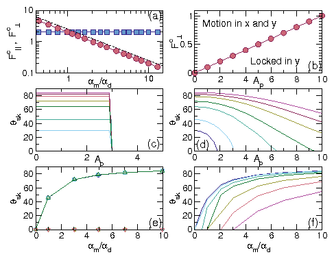
Physical Review B 94, 094413 (2016)

Magnus-Induced Dynamics of Driven Skyrmions on a Quasi-One-Dimensional Periodic Substrate

C. Reichhardt and C. J. Olson Reichhardt

Theoretical Division, Los Alamos National Laboratory, Los Alamos, New Mexico 87545, USA

(Received 31 May 2016; revised manuscript received 28 July 2016; published 13 September 2016)

We numerically examine driven skyrmions interacting with a periodic quasi-one dimensional substrate where the driving force is applied either parallel or perpendicular to the substrate periodicity direction. For perpendicular driving, the particles in a purely overdamped system simply slide along the substrate minima; however, for skyrmions where the Magnus force is relevant, we find that a rich variety of dynamics can arise. In the single skyrmion limit, the skyrmion motion is locked along the driving or longitudinal direction for low drives, while at higher drives a transition occurs to a state in which the skyrmion moves both transverse and longitudinal to the driving direction. Within the longitudinally locked phase we find a pronounced speed up effect that occurs when the Magnus force aligns with the external driving force, while at the transition to transverse and longitudinal motion, the skyrmion velocity drops, producing negative differential conductivity. For collectively interacting skyrmion assemblies, the speed up effect is still present and we observe a number of distinct dynamical phases, including a sliding smectic phase, a disordered or moving liquid phase, a moving hexatic phase, and a moving crystal phase. The transitions between the dynamic phases produce distinct features in the structure of the skyrmion lattice and in the velocity-force curves. We map these different phases as a function of the ratio of the Magnus term to the dissipative term, the substrate strength, the commensurability ratio, and the magnitude of the driving force.
I. INTRODUCTION
II. SIMULATION
III. SINGLE SKYRMION LIMIT
IV. COLLECTIVE EFFECTS
A. Dynamic phase diagrams
V. VARIED SKYRMION DENSITIES
VI. SUMMARY
References

I.  INTRODUCTION

There are numerous examples of systems that can be described as individual particles or a collection of particles interacting with a periodic quasi-one dimensional (q1D) substrate, including colloids on optically created q1D substrates [1,2,3,4] or q1D line pinning [5,6,7], vortices in type-II superconductors with one-dimensional (1D) periodic thickness modulations [8,9,10,11,12,13,14], and various frictional systems [15]. In the colloidal systems a variety of commensurate-incommensurate states can occur such as crystal, smectic, and disordered structures [1,2,3,4,5]. In vortex systems, under an applied driving force a series of peaks or dips in the critical depinning force can appear which are also associated with commensuration effects [8,9,10,12]. These systems, as well as other systems of particles interacting with two-dimensional (2D) periodic substrates, can exhibit a variety of depinning phenomena and dynamic phases, and can undergo transitions between different dynamic phases that produce changes in the configuration of particles and flow behavior as well as features in the velocity-force curves [7,8,14,15,16,17,18,19,20,21,22,23]. In a 2D overdamped system with a q1D periodic substrate, pinning-depinning phenomena and distinct dynamical phases appear only when the driving force is applied parallel to the substrate periodicity direction. If the drive is applied perpendicular to the substrate periodicity direction, there is no pinning effect from the substrate and the particles simply slide along the driving direction, resulting in a linear velocity-force curve.
In overdamped systems in the absence of a substrate, individual particles move in the same direction as the applied driving force. In some systems, additional transverse forces can arise when a Magnus force term FM with the form z×v is present, which causes a rotation of the particle velocity into the direction perpendicular to the net applied forces. When particles with a Magnus force term are driven perpendicular to the periodicity direction of a q1D periodic substrate, the Magnus term creates a coupling between the motion of the particles parallel and perpendicular to the driving force, so the effect of the q1D pinning becomes relevant. A Magnus term can arise for vortices in superconductors and superfluids; however, in the case of superconducting systems it is normally very small and has little effect on the depinning and sliding dynamics. Recently a new particle-like system, skyrmions in chiral magnets, was discovered in which the Magnus force is much stronger [24,25,26,27]. Since the initial observation of skyrmions in magnetic systems, there has been a rapid growth in the field as an increasing number of systems have been identified that support skyrmions, including materials in which skyrmions are stable at room temperature [28,29,30,31,32]. Another reason for the growing interest in this field is that skyrmions could be used as magnetic information carriers, making them promising for spintronic applications [33].
In order for spintronic or other applications of skyrmions to be realized, it is necessary to have an understanding of how skyrmions move in different types of nanostructured samples. Skyrmions can be moved by an applied current [27,34,35], and have been shown to exhibit a pinned to sliding transition based on effective velocity-force curves that can be constructed by measuring changes in the transport properties [36,37]. Velocity-force curves can also be obtained by directly imaging the skyrmion motion [27,28,38]. In many cases the skyrmion critical depinning force is very low, and this was argued to be a result of the Magnus term which permits skyrmions to move around a pinning site and avoid trapping rather than moving toward the pinning site and becoming trapped as in the case of overdamped systems [39,40,41]. Under an applied driving force, the Magnus term causes the skyrmion to move at an angle with respect to the driving direction, producing a skyrmion Hall angle θsk [27,35,39]. In a pin-free system θsk is constant and is proportional to the ratio of the Magnus term αm to the damping term αd, θsk ∝ tan−1md). When pinning is present, however, θsk becomes drive-dependent as the skyrmions make a side jump motion when interacting with an individual pinning site, which reduces the Hall angle [41,42,43]. As the drive is increased, the side jump effect is reduced and θsk approaches the clean value limit. In Ref. [44] an imaging technique provided direct evidence for the drive dependence of the skyrmion Hall angle, with a linear dependence of the ratio of the transverse to longitudinal skyrmion velocity as a function of drive. These studies focused on pointlike pinning or circular pinning sites; however, it should also be possible to create line-like pinning using various lithographic techniques such as 1D periodic thickness modulation, periodic magnetic strips, or optical techniques.
In this work we use a particle-based simulation to examine individual and collectively interacting skyrmions in a 2D system in the presence of a q1D periodic substrate, as described Section II. The particle model is based on a modified Thiele equation [40,41,42,43,45] which agrees well with continuum-based simulations in the limit where the overlap of adjacent skyrmions is small [40]. In Section III we describe the results for the single skyrmion limit, where if the drive is applied parallel to the substrate periodicity direction, we find that unlike the case of pointlike pinning, the depinning threshold does not decrease with increasing Magnus term magnitude since the skyrmions cannot simply move around the pinning sites. When the drive is applied perpendicular to the substrate periodicity direction, in the overdamped limit there is no depinning threshold and the skyrmions simply slide without any structural change for increasing drive, producing a linear velocity-force curve. On the other hand, when there is a finite Magnus term we observe a rich variety of dynamical behaviors even in the single skyrmion limit. For perpendicular drives, the skyrmion motion is locked in the drive direction at low drives until a critical driving force is reached at which the skyrmions also start move partially parallel to the substrate periodicity direction, coinciding with a sudden drop in the net velocity of the skyrmion and producing a negative differential conductivity effect. At higher drives the skyrmion velocity again increases with increasing drive. We also show that when the skyrmion motion is locked in the direction of the drive, a speed up effect occurs where the skyrmion moves faster than it would in the overdamped limit due to the alignment of the pinning-induced velocity from the Magnus term with the driving force direction. This speed up effect was initially observed in simulations of pointlike pinning [41,42]; however, the effect is more easily controlled with q1D pinning. When the driving is applied parallel to the substrate periodicity direction, there is no speed up effect but instead an enhanced damping appears. In Section IV we examine collectively interacting skyrmions and show that the same speed up effect and transition from locked motion in the direction of drive to motion in both the longitudinal and transverse directions occur. In addition, a series of dynamical phases appear that can be characterized by the structure of the moving skyrmions, and the transitions between these phases are correlated with distinct features in the transport curves. The phases include a moving smectic and a moving liquid which can undergo dynamical ordering transitions into a moving quasi-ordered hexatic lattice or a moving crystal. We map out the dynamic phases as a function of the substrate strength and the ratio of the Magnus force to the dissipative term. In Section V we examine the effect of changing the ratio of the skyrmion density to the periodicity of the substrate, where we observe chainlike structures consisting of multiple rows of skyrmions per substrate minimum. We also check for hysteresis across the dynamic phase transitions.
We note that although this work focuses on skyrmions in chiral magnets, our results should also be relevant to other systems in which skyrmion textures can arise, such as p-wave superconductors [46,47,48,49] and other multiple band superconductors [50]. Skyrmion states can also arise in semiconductors so it may be possible to examine pinning-depinning phenomenon in such systems [51,52,53]. Superconducting vortices can exhibit a Magnus effect [54,55] that is generally very small; however, in materials such as clean YBCO samples, large Hall angles have been measured [56]. Additionally, it was recently proposed that vortices in topological insulators can have a strong Magnus term [57]. Vortex pinning in which the Magnus force is important can also arise for vortices in neutron star superfluids [58,59]. Finally, it is also possible to add pinning to the vortices in Bose-Einstein condensates, where the dissipation of the vortices is strong enough to produce a significant Magnus force [60].
Fig1.png
Figure 1: (Color online) Skyrmions (red dots) at a density of ρs=0.1 on a periodic quasi-one-dimensional substrate with pinning strength Ap=1.0. Here the substrate periodicity is in the x-direction and we consider dc driving FD|| in the parallel or x direction (blue arrow) and FD in the perpendicular or y direction (red arrow). The dark green regions indicate the locations of the substrate potential maxima.

II.  SIMULATION

In Fig. 1 we show a snapshot of our 2D system, which has periodic boundary conditions in the x and y directions and contains a q1D periodic sinusoidal substrate potential with period a and periodicity running along the x direction. There are N skyrmions which are trapped in the potential minima. The initial skyrmion positions are obtained through simulated annealing, after which we apply a dc driving force Fdc in either the parallel or x direction, Fdc=FD||x, or in the perpendicular or y direction, Fdc=FDy, and we measure the resulting skyrmion velocity. The dynamics of a single skyrmion i are obtained using the following equation of motion:
αdvi + αm
^
z
 
×vi = Fssi + Fspi + Fdc
(1)
where ri is the skyrmion position, vi=dri/dt is the skyrmion velocity, Fssi is the skyrmion-skyrmion interaction force, Fspi is the skyrmion-pinning interaction force, and Fdc is the external driving force. The first term is the damping αd which aligns the skyrmion velocity in the direction of the net external forces, and the second term is the Magnus force with prefactor αm, where the cross product creates a velocity component perpendicular to the net external forces. To maintain a constant magnitude of the skyrmion velocity we apply the constraint αd2 + α2m = 1. This constraint is used for convenience so that the skyrmion total velocity curves obtained from the measure 〈Vtot〉 = √{〈V||2 + 〈V2} will be equal in the pin free case for all sets of αm and αd. The skyrmion Hall effect can be characterized by measuring the ratio R = 〈V〉/〈V||〉 of the skyrmion velocity in the perpendicular direction, 〈V〉 = N−1iN vi ·y, to that in the parallel direction, 〈V||〉 = N−1iN vi ·x. The skyrmion Hall angle is θsk = tan−1(R). In a clean system, R has a constant value given by Rmd. The substrate force Fspi = −∇U(xi) x arises from a periodic sinusoidal potential
U(xi) = U0cos(2πxi/a)
(2)
where xi=ri ·x, a is the periodicity of the substrate, and we define the substrate strength to be Ap = 2πU0/a. The skyrmion-skyrmion interaction force is repulsive, which favors the formation of a triangular lattice in a clean system. It has the form Fssi = ∑j=1NK1(Rij)rij where Rij = |rirj|, rij = (rirj)/Rij, and K1 is the modified Bessel function. This interaction falls off exponentially for large Rij. The sample is of size L ×L and the skyrmion density is ns=N/L2. Previous studies of skyrmions on a similar q1D periodic substrate focused on Magnus-induced Shapiro steps, which arise when an additional ac drive is present [1].
In this work we assume that the skyrmions are true point particles that show no internal distortion; however, actual skyrmions can undergo shape distortions, particularly near the helical to skyrmion phase transition where elongated skyrmions have been observed [25]. The point particle model is a reasonable approximation for the behavior when the overlap between skyrmions is small. In this regime, comparisons between point particle models and continuum models of skyrmions are in good agreement [40,42]. It is possible that linelike pinning could more strongly distort the skyrmion core in one direction, which could affect the dissipation. Such an effect would be stronger for large skyrmions, so our results are best applied to the case of relatively small and stiff skyrmions.

III.  SINGLE SKYRMION LIMIT

Fig2.png
Figure 2: (Color online) Parallel (〈V||〉, blue) and perpendicular (〈V〉, red) velocities for a single skyrmion driven in the parallel (x) direction vs the driving force magnitude FD||. The substrate potential strength is Ap=2.0. (a) In the overdamped limit of αmd = 0, the motion is locked in the parallel direction and there is a critical depinning force of Fc|| = 2.0. (b) At αmd = 2.06, there is a finite velocity signal in both directions. (c) At αmd = 9.962, 〈V||〉 is diminished compared to 〈V〉. (d) 〈Vtot〉 = √{〈V||2 + 〈V2} vs FD|| for αmd=9.962. The dashed line indicates the response 〈Vtot0〉 for a clean system with Ap=0. The 〈Vtot0〉 curve does not vary as a function of αmd.
Fig3.png
Figure 3: The skyrmion location (red circle), trajectory (line), and substrate potential (green) for the system in Fig. 2 just above depinning. The dc drive FD|| is in the positive x-direction. (a) At αmd = 0.4364, the skyrmion moves at an angle of θsk = 23.6° with respect to the driving direction. (b) At αmd = 9.9624, θsk = 84.26°.
We first consider the case of a single skyrmion, N=1. In Fig. 2(a) we plot 〈V||〉 and 〈V〉 versus FD|| for an overdamped system with αmd = 0 where the skyrmion is driven parallel to the substrate periodicity direction and the substrate strength is Ap=2.0. Here, 〈V〉 = 0 for all FD||, and there is a depinning transition at Fc|| = Ap = 2.0, above which 〈V||〉 becomes finite. Figure 2(b) shows that at αmd = 2.06, the depinning threshold is still Fc|| = 2.0, but the skyrmion now moves both parallel and perpendicular to the driving direction above depinning. The slope of the 〈V〉 curve is approximately twice that of the 〈V||〉 curve. At αmd = 9.962, Fig. 2(c) shows that the depinning threshold is unchanged at Fc|| = 2.0 but that the perpendicular velocity has become much more pronounced. We find that Fc|| is independent of αmd for driving in the parallel direction. This is in contrast to observations of skyrmions interacting with randomly placed [39,40,43] or periodic [41] arrays of pointlike pinning sites, where Fc|| decreases with increasing αmd. For pointlike pinning, as the increasing Magnus term causes the skyrmion trajectories to become increasingly curved, the skyrmions can more easily circle around the pinning sites without becoming trapped, and this has been argued to be one of the reasons that the depinning thresholds are so low in skyrmion systems. In the case of the q1D periodic substrate, the pinning potential is planar in one direction, making it impossible for the skyrmions to circle around the pinning locations. As a result, planar or linelike pinning sites produce much stronger skyrmion pinning than pointlike pinning sites.
In Fig. 2(d) we plot the total velocity 〈Vtot〉 = √{〈V||2 + 〈V2} for the system in Fig. 2(c) with αmd=9.962. The dashed line indicates the response 〈Vtot0〉 in a clean system with Ap=0 for comparison. Here, for any finite value of Ap, 〈Vtot〉 < 〈Vtot0〉 for parallel driving, indicating that the effective damping is enhanced by the substrate. In Fig. 3(a) we plot the skyrmion trajectory just above depinning for the system in Fig. 2 at αmd = 0.4364. The skyrmion follows a straight trajectory oriented at an angle, the skyrmion Hall angle θsk=23.6°, with respect to the external drive. Figure 3(b) shows that at αmd = 9.9624, the skyrmion moves at a much steeper angle to the external drive, with θsk just under the clean limit value of θsk=84.26°.
Fig4.png
Figure 4: 〈V||〉 and 〈V〉 for a single skyrmion driven in the perpendicular (y) direction vs the driving force magnitude FD. The substrate potential strength is Ap = 2.0. (a) At αmd = 0.577, the skyrmion motion is initially locked in the perpendicular direction, and a transition to motion in both the parallel and perpendicular directions occurs at Fc = 3.5. (b) At αmd = 2.06, Fc is decreased. (c) At αmd = 9.962, Fc is even smaller. (d) 〈Vtot〉 vs FD, where the dashed line indicates the response 〈Vtot0〉 in a system with Ap = 0. Here 〈Vtot〉 > 〈Vtot0〉, indicating the existence of a speed up effect.
Fig5.png
Figure 5: The skyrmion location (red circle), trajectory (line), and substrate potential (green) for the system in Fig. 4(c,d) at αmd = 9.962. The dc drive FD is in the positive y-direction. (a) At FD = 0.17, the motion is locked in the driving direction. (b) At FD = 0.6, the skyrmion is moving at an angle with respect to the dc drive. (c) FD = 1.0. (d) FD = 3.0.
In Fig. 4 we show 〈V〉 and 〈V||〉 versus FD for a single skyrmion driven along the y direction, perpendicular to the substrate periodicity direction. In the overdamped limit of αmd = 0, 〈V||〉 = 0 for all FD, there is no depinning threshold for motion in the driving direction, and 〈V〉 increases linearly with FD. When αmd > 0, there is a range of FD over which the skyrmion motion is locked in the perpendicular or y direction, and once FD reaches a critical threshold Fc, a transition occurs to motion in both the perpendicular and parallel directions. This is illustrated in Fig. 4(a) for αmd = 0.577, where 〈V||〉 becomes finite at FD = Fc=3.5. This transition coincides with a small drop in 〈V〉. As αmd is increased, the value of Fc decreases while the magnitude of the drop in 〈V〉 at the transition point increases, as shown in Fig. 4(b,c) for αmd = 2.06 and 9.962, respectively. For FD > Fc, 〈V〉 increases with increasing FD. In Fig. 5(a) we plot the skyrmion trajectory for the system in Fig. 4(c,d) with αmd = 9.962 at FD = 0.17, where the skyrmion motion is locked in the drive direction. At FD=0.6 in Fig. 5(b), the skyrmion moves in both the longitudinal and transverse directions with a sinusoidal undulation. In Fig. 5(c) at FD = 1.0, the angle θsk between the direction of skyrmion motion and the driving direction is larger, while at FD=3.0 in Fig. 5(d), θsk is even larger. For high enough drives, θsk approaches the clean limit value of θsk=84.26°. This shows that the skyrmion Hall angle has a much stronger dependence on the external driving force for perpendicular driving than for parallel driving.
In Fig. 4(d) we plot the net velocity 〈Vtot〉 versus FD at αmd = 9.962. The dashed line shows the response 〈Vtot0〉 for a system with Ap = 0. Just above the depinning threshold Fc=0.2 for motion in the parallel direction, we observe negative differential conductivity (NDC), where the net velocity of the skyrmion decreases with increasing drive. Negative differential conductivity is a phenomenon often found for charge transport in semiconductors [61], and it can be useful in constructing logic devices, which suggests that the construction of magnetic versions of semiconductor logic devices using skyrmions may be possible. NDC has also been observed for vortices in type-II superconductors driven over periodic pinning arrays, where it is associated with transitions in the flow states [18,20]. Previous simulation studies of skyrmions driven over 2D periodic arrays, where the skyrmion Hall angle changes as a function of drive, also showed NDC [41], while in both particle-based and continuum simulations of skyrmions interacting with an isolated circular pinning site, the skyrmion velocity can drop to zero at high enough drive when it becomes possible for the pinning site to capture a skyrmion [42].
Figure 4(d) also shows that 〈Vtot〉 is always larger than the clean limit value of 〈Vtot0〉, indicating that the q1D substrate enhances the skyrmion velocity compared to the clean limit. For example, at the parallel depinning transition point FD=Fc=0.2, 〈Vtot〉 ≈ 2.0, while in the pin-free limit, 〈Vtot0〉 = FD=0.2. Such speed up effects were first observed in continuum and particle based simulations for skyrmions interacting with a single pinning site [42] and with a periodic array of pinning sites [41]. In the case of q1D planar pinning sites, it is easier to see that this effect arises due to the Magnus force.
For a finite Ap, under a perpendicular drive FD the dissipative skyrmion motion term produces a finite contribution to 〈V〉 and no contribution to 〈V||〉; however, the Magnus term generates a force component F||mmFD parallel to the substrate periodicity direction which is countered by the pinning force F||p that has a maximum value of F||pdAp. As a result, 〈V||〉 > 0 for a perpendicular drive of FDFc where Fc satisfies F||m = Fp, which gives αm Fc = αdAp, or Fc = Apdm). To check this expression, we note that setting Ap = 2.0 and αdm = 0.10038 gives Fc ≈ 0.2, in agreement with the value observed in Fig. 4(d). As long as FD < (αdm)Ap, the skyrmion motion is locked in the perpendicular direction and 〈V||〉 = 0; however, from the Magnus term the skyrmion picks up a perpendicular velocity enhancement that reaches a maximum value of of FmmAp at Fc. In addition to this pinning-induced velocity contribution, FD produces a perpendicular velocity through the damping term, so that the net maximum perpendicular skyrmion velocity at Fc is given by
Vmax〉 = αdFc + αmAp.
(3)
In Fig. 4(c,d), αd = 0.09987 and αm = 0.995, so that at the transition point FD = Fc = 0.2 Eq. 3 gives 〈Vmax〉 = 2.001, in agreement with the maximum values of 〈V〉 and 〈Vtot〉 in Fig. 4(c,d). According to Eq. 3, below the parallel depinning threshold Fc the skyrmion velocity increases linearly with the pinning strength Ap. Once the skyrmion depins in the parallel direction at Fc, it experiences an oscillating pinning force, destroying the speed up effect and causing 〈V〉 to drop. At high drives the system gradually approaches the clean value limit in which the velocity increases linearly with drive according to 〈V〉 = αdFD and 〈V||〉 = αmFD, as also observed in systems with periodic and random pointlike pinning [43]. In Fig. 6 we plot 〈Vtot〉 versus FD for Ap = 0.5, 1.0, 2.0, 3.0, 4.0, and 5.0 at αmd = 9.962. Here, both Fc and the maximum value of 〈Vtot〉 increase with Ap, in agreement with Eq. 3.
Fig6.png
Figure 6: 〈Vtot〉 vs FD at αmd = 9.962 for Ap = 0.5, 1.0, 2.0, 3.0, 4.0, and 5.0, from bottom to top. The dashed line is 〈Vtot0〉 with Ap = 0.
Fig7.png
Figure 7: (a) The depinning forces Fc|| and Fc at which motion in the direction parallel to the substrate periodicity occurs vs αmd for samples with Ap=2.0. Blue squares: Fc||, for parallel driving, has no dependence on αmd. Red circles: Fc, for perpendicular driving, can be fit to Fc ∝ (αmd)−1 (dashed line). (b) Fc vs Ap at αmd = 9.962. Here Fc increases linearly with Ap. (c) The skyrmion Hall angle θsk vs Ap for parallel driving under constant FD|| = 3.0 at αmd = 9.9624, 7.018, 4.924, 3.042, 2.06, 0.98, 0.577, and 0, from top to bottom. Here θsk is constant until Ap > 3.0, after which the system becomes pinned. (d) θsk vs Ap for perpendicular driving under constant FD=3.0 at αmd = 9.9624, 7.018, 4.924, 3.042, 2.06, 0.98, 0.577, and 0, from top to bottom. Here θsk shows a strong dependence on Ap. (e) θsk vs αmd at constant F||D = 3.0 for Ap = 0.0 (circles), 1.0 (squares), 2.0 (diamonds), 3.0 (up triangles), 5.0 (left triangles), and 10.0 (down triangles). Here, in the moving state for Ap < 3.0, θsk is independent of Ap and follows the upper curve, while in the pinned state for Ap ≤ 3.0, θsk=0 (lower curve). (f) θsk vs αmd at constant F||D = 3.0 for Ap = 0, 1.0, 2.0, 3.0. 5.0, 7.0, and 10.0, from top to bottom, showing that for any fixed value of αmd, θsk decreases with increasing Ap.
In Fig. 7(a) we plot the depinning force Fc|| versus αmd for parallel driving for the system in Fig. 2 along with the force Fc at which sliding along the parallel direction occurs for the system in Fig. 4 with perpendicular driving. The parallel driving produces a parallel force F||ddFD|| which acts against the maximum pinning force of αd Ap, so that at depinning, αdFc|| = αdAp, indicating that Fc|| = Ap and that Fc|| is independent of αmd, in agreement with the results in Fig. 7(a), where Fc|| is constant. In contrast, Fc obeys Fc ∝ (αmd)−1, as indicated by the dashed line in Fig. 7(a), so that Fc diverges at αm = 0 when the skyrmions stay locked in the direction of drive in the overdamped limit. In this case, at depinning under the perpendicular drive, the Magnus force produces a parallel force Fm||m Fc that is equal to the force produced by the pinning, giving αm Fc = αd Ap and Fc = Apmd)−1. Figure 7(b) shows Fc versus Ap for αmd = 9.962, showing a linear increase with Ap with a slope of αdm.
We have also examined the pinning effects on the skyrmion Hall angle θsk by measuring the ratio R=〈V〉/〈V||〉 for fixed external drive, which would correspond to a constant current in an experiment. Here θsk = tan−1(R). In Fig. 7(c) we plot θsk versus Ap for parallel driving at FD|| = 3.0 for αmd values of 9.9624, 7.018, 4.924, 3.042, 2.06, 0.98, 0.577, and 0. These correspond to pin free values of θsk of 84.27°, 81.89°, 78.52°, 71.8°, 64.1°, 44.42°, 30°, and 00, respectively. Here, regardless of the value of αmd, θsk is equal to the pin free value for Ap < 3.0 and drops to zero in the pinned state for Ap ≥ 3.0, indicating that θsk has no pinning dependence in the flowing state for parallel driving. For perpendicular driving, as shown in the plot of θsk versus Ap in Fig. 7(d), θsk depends strongly on Ap, and gradually approaches 0 as Ap increases.
In Fig. 7(e) we plot θsk versus αmd at a constant FD|| = 3.0 for Ap = 0.0, 1.0, 2.0, 3.0, 5.0, and 10.0. For Ap < 3.0, θsk is equal to the pin free value, while θsk=0 for Ap ≥ 3.0 when the system is pinned. For perpendicular driving, we plot θsk versus αmd at constant FD=3.0 in Fig. 7(f) for Ap = 0, 1.0, 2.0, 3.0, 5.0, 7.0, and 10.0. Here, for any particular value of αmd, θsk decreases with increasing Ap. We note that for pointlike pinning sites of the type considered in previous work, θsk varies with Ap for both parallel (x) and perpendicular (y) driving, since the pointlike pinning site can induce both x and y direction forces on any skyrmion that passes through it. In contrast, linelike pinning of the type considered here only exerts x direction forces. Overall, these results suggest that linelike pinning can provide an effective method to control the direction of the skyrmion motion, which is important for applications. We note that the form of the linelike pinning in real systems could differ from the sinusoidal shape we consider here. For example, an experimental substrate could have a parabolic or linear form. Regardless of the details of the substrate shape, most of the general features we observe should be robust since it is the direction of the force exerted by the linelike pinning that is the dominant factor in controlling the dynamics of the skyrmion.

IV.  COLLECTIVE EFFECTS

Fig8.png
Figure 8: (a) 〈V||〉 (blue) and 〈V||〉 (red) vs FD for a system with multiple interacting skyrmions at αmd = 4.925, Ap = 1.0, and skyrmion density ns = 0.16. (b) The fraction of sixfold-coordinated skyrmions P6 vs FD. In the moving smectic phase the motion is locked along the perpendicular direction. Also marked are the moving liquid, moving hexatic, and moving crystal phases. (c) R = 〈V〉/〈V||〉 vs FD.
Fig9.png
Figure 9: The structure factor S(k) for the different phases for the system in Fig. 8. (a) The moving smectic phase at FD = 0.1. (b) The moving liquid phase at FD = 0.5. (c) The moving hexatic phase at FD = 1.0. (d) The moving crystal phase at FD = 1.2.
Fig10.png
Figure 10: (a) 〈V〉 vs FD for the system in Fig. 8 at αmd = 4.925 for Ap = 0.25, 0.5, 0.75, 1.0, 1.25, and 1.5, from bottom to top, showing more clearly the cusp at the ML-MH/MC transition. MS: moving smectic; ML: moving liquid; MH: moving hexatic; MC: moving crystal. The dashed line is the response for a sample with Ap = 0. (b) 〈V〉 vs FD for the same system with Ap = 1.0 for αmd = 9.995, 7.017, 4.925, 3.0, and 2.06, from top right to bottom right. The dashed line indicates the response in an overdamped system with αmd = 0.
Name Label Lattice structure
Stationary Phase:
Pinned Smectic PS All dislocation pairs have Burgers vectors aligned along same axis
Moving Phases:
Moving Smectic MS All dislocation pairs have Burgers vectors aligned along same axis
Moving Liquid ML Disordered structure
Moving Hexatic MH Hexatic ordering
Moving Crystal MC Triangular crystal ordering with symmetry axis aligned along driving direction
Locked Moving Floating Solid LMFS Triangular crystal ordering, no particular orientation, motion only in perpendicular direction
Moving Floating Solid MFS Triangular crystal ordering, no particular orientation, motion in both parallel and perpendicular directions
Table 1: List of dynamic phases and the skyrmion lattice structure associated with them.
We next consider the case of multiple interacting skyrmions. In Fig. 8(a) we plot 〈V||〉 and 〈V〉 versus FD for a system with αmd = 4.925 and Ap = 1.0 at a skyrmion density of ns = 0.16, where the ratio of the substrate lattice constant a to the skyrmion lattice constant ask is a/ask = 1.3098. Here we observe the same features in 〈V||〉 and 〈V〉 that appeared in the single skyrmion case, including a longitudinally locked phase, negative differential conductivity, and a speed up effect. There are several differences, including additional cusps in the velocity-force curves at higher drives which are correlated with changes in the collective dynamics. Figure 8(b) shows P6, the fraction of sixfold-coordinated skyrmions, versus FD. Here P6=N−1i=1Nδ(zi−6), where zi is the coordination number of skyrmion i obtained from a Voronoi construction. In the longitudinally locked regime, the pinning is strong enough that the skyrmions form 1D incommensurate chains moving in the perpendicular direction, so that the skyrmion lattice structure exhibits a number of aligned topological defects. Figure 9(a) shows the structure factor S(k)=N−1|∑iN exp(−ik ·ri)|2 for the moving smectic (MS) phase at FD = 0.1, where the system forms stripe like features indicative of smectic ordering. For 0.18 < FD < 0.84, 〈V〉 gradually decreases with increasing FD and the skyrmions form a disordered or moving liquid (ML) state, as indicated by the ring structure in Fig. 9(b), which shows S(k) at FD = 0.5. There are still two satellite peaks in S(k) along the ky = 0 line that are produced by the 1D periodicity of the substrate.
In Fig. 8, a cusp appears in 〈V〉 near FD = 0.85, above which 〈V〉 starts to increase with increasing FD again. This cusp is correlated with a sharp increase in P6 to P6=0.93, which indicates that the system has dynamically reordered into a triangular lattice containing a small number of fivefold and sevenfold-coordinated defects. We call this a moving hexatic (MH) state, and it exhibits smeared sixfold peaks in S(k), as shown in Fig. 9(c) at FD = 1.0. Near FD = 1.16, there is another jump in P6 in Fig. 8(b) to P6 ≈ 1.0. Here the system forms a moving crystal (MC) phase, and the corresponding structure factor in Fig. 9(d) shows much more pronounced peaks in S(k). In Fig. 8(c) we plot the velocity ratio R versus FD. There is a jump to a finite value of R at the onset of the ML phase, and a cusp at the ML-MH transition. We do not observe any particular cusps or jumps in the transport curves at the MH-MC transition. In Fig. 10(a) we plot 〈V〉 versus FD for the system in Fig. 8 for Ap = 0.25, 0.5, 0.75, 1.0, 1.25, and 1.5, with a dashed line indicating the response for Ap = 0. Here the cusp in 〈V〉 at the ML-MH/MC transition can be more clearly seen. Additionally, the velocity noise fluctuations are substantially reduced in the dynamically ordered MH/MC states. In Fig. 10(b) we show 〈V〉 versus FD for samples with Ap = 1.0 at αmd = 9.995, 7.017, 4.925, 3.0, and 2.06. The MS-ML transition shifts to higher values of FD with decreasing αmd, while the cusps at higher FD indicate the ML-MH/MC transition is still present.
The onset of different dynamical phases as a function of external driving has been observed in various overdamped systems, including colloids and vortices moving over q1D periodic substrates, but only for a driving force applied parallel to the substrate periodicity direction. In those systems there is generally a disordered flow phase above depinning [7,14,62,63] with a transition to a moving ordered phase at higher drives [14,62,63]; however, negative differential conductivity does not occur. For systems of particles moving over 2D periodic substrates, such as egg carton or muffin tin potentials, negative differential conductivity can arise [18,20,64,65,66]. In previous simulations of skyrmions driven over random arrays, it was shown that there can be a transition from a disordered phase above depinning to a moving crystal phase at higher drive [43], while there are extensive studies of dynamically ordered phases as a function of increasing driving force for vortices driven over random pinning arrays [67,68,69,70].
Fig11.png
Figure 11: The same system as in Fig. 8 but for driving parallel to the substrate periodicity direction. (a) 〈V||〉 (red) and 〈V〉 (blue) vs FD||, along with the corresponding dV||〉/dFD|| (yellow) and dV〉/dFD|| (green) curves. (b) P6 vs FD|| showing transitions between the pinned smectic (PS) state, the moving liquid (ML), and the moving crystal (MC). (c) Velocity ratio R vs FD||.
We have also considered the case of interacting skyrmions subjected to a drive that is applied parallel to the substrate periodicity. In Fig. 11(a) we plot 〈V||〉 and 〈V〉 versus FD|| for a system with αmd = 4.925, Ap = 1.0, and ns = 0.16. Here the depinning threshold Fc||Ap, and in general for fixed ns, Fc|| is independent of αmd and increases linearly with Ap, similar to the results for the single skyrmion case shown in Fig. 2. The interacting skyrmions form an immobile pinned smectic (PS) phase which depins plastically into a moving liquid (ML) state. The ML dynamically orders into a moving crystal (MC) phase near FD|| = 4.0, as is illustrated by the plot of P6 versus FD|| in Fig. 11(b). There is only a small cusp in the transport curves at the ML-MC transition, as indicated by the dV||〉/dFD|| and dV〉/dFD plots in Fig. 11(a). This contrasts with the significantly larger cusps that appear for perpendicular driving. Additionally, the velocity fluctuations are strongly suppressed once the system enters the MC phase. The MC phase that forms for parallel driving generally contains more dislocations than the corresponding MC phase that appears for perpendicular driving, so the parallel driving MC phase can better be described as a moving hexatic. In Fig. 11(c), the plot of the velocity ratio R versus FD|| shows that the PS-ML transition is sharp. There is little curvature in R for higher drives, in contrast to the perpendicular driving case where R increases much more smoothly as a function of drive.

A.  Dynamic phase diagrams

Fig12.png
Figure 12: The dynamic phase diagram as a function of FD vs αmd for Ap = 1.0 and ns = 1.0 showing the moving smectic (MS), moving liquid (ML), moving hexatic (MH), and moving crystal (MC) phases. Here the width of the MS phase diverges with decreasing αmd.
Fig13.png
Figure 13: The dynamic phase diagram as a function of FD vs Ap at αmd = 4.925 and ns = 1.0 showing the moving solid (MS), moving liquid (ML), and moving crystal (MC) phases. For weaker substrate strengths, a longitudinally locked moving floating solid (LMFS) phase appears which transitions with increasing FD into a phase called the moving floating solid (MFS) that moves in both the parallel and perpendicular directions.
By conducting a series of simulations and examining the features in 〈V〉 and P6, we can map out the dynamic phases, as shown in Fig. 12 as a function of FD versus αmd for a system with Ap = 1.0. The extent of the MS phase diverges at small αmd, while the extent of the ML phase decreases with decreasing αmd. Based on features in the P6 curves, we find that the MH phase appears only for αmd > 3.0, and that it grows in extent with increasing αmd. We have also considered the case of varied Ap, and in Fig. 13 we plot the dynamic phase diagram for FD versus Ap for a system with αmd = 4.925. Here, the extent of the MS phase increases with increasing Ap, and the onset of the MC phase shifts to higher FD. There is also a thin strip of MH phase that appears for Ap > 0.1 (not shown). For weak enough Ap, additional dynamical phases appear when the skyrmions do not remain confined to the potential minima but form a completely triangular lattice that is weakly coupled to the substrate. At low FD, the system forms a MS phase for Ap ≥ 0.1, while for Ap < 0.1 we observe a moving longitudinally locked floating solid (LMFS) which travels strictly along the perpendicular direction. Here, the skyrmions are pinned by the substrate in the parallel direction but can move freely along the perpendicular direction. At higher drives the LMFS transitions to a moving floating solid (MFS) phase in which the skyrmions depin from the weak substrate and begin to move in both the parallel and perpendicular directions.
Figure 13 shows that the value of FD at which the system depins in the parallel direction and ceases to have its motion locked along the perpendicular direction drops substantially from the MS to the LMFS phase. This is similar to what is observed at an Aubry transition which arises in a 1D incommensurate Frenkel-Kontorova system, where when the substrate is weak enough, the pinning effectively vanishes and the particles float over the substrate [71]. It has been argued that an Aubry-like transition should occur for 2D systems such as sliding colloids [72], and that this transition could be relevant to the phenomenon called superlubricity [22]. In recent simulations of colloids on 2D substrates, it was shown that the 2D Aubry transition is first order and is associated with a sharp drop in the effective friction [72]. This is similar to what we observe, where there is a sharp drop in the parallel depinning force at the MS-LMFS transition, suggesting that this transition is first order.
Fig14.png
Figure 14: (a) Image of skyrmion locations (red dots) on the substrate potential (green) for the system in Fig. 13 in the moving floating solid (MFS) state at Ap = 0.04 and FD = 0.0001. (b) The same for the moving crystal (MC) at FD = 1.0, showing the change in the orientation of the lattice. The LMFS state has the same orientation as the MFS state.
Fig15.png
Figure 15: 〈V〉 vs FD for the system in Fig. 13 at Ap = 0.01 (dark blue), 0.02 (light blue), 0.03 (green), and 0.04 (pink). (b) The corresponding P6 vs FD showing that at Ap = 0.01 the system remains ordered, while at Ap = 0.04, the system goes from an ordered state into a disordered state and then dynamically orders at higher drives.
There is a window of Ap in the phase diagram of Fig. 13 in which the MFS can transition to a ML phase, which then dynamically orders into an MC phase at higher drives, while for low enough Ap, the ML phase is lost and no structural changes occur in the moving skyrmion lattice as a function of FD. The orientation of the skyrmion lattice with respect to the substrate periodicity direction is generally different in the MC and the MFS phases. In the MC, the lattice is aligned with the substrate minima, while in the MFS there is no particular matching between the lattice orientation and the substrate periodicity direction, as shown in the images in Fig. 14(a,b) at Ap = 0.04 for FD = 0.0001 and FD=1.0. In Fig. 15(a) we plot 〈V〉 versus FD curves from the phase diagram in Fig. 13 for Ap = 0.01, 0.02, 0.03, and 0.04. At Ap = 0.01, 〈V〉 is smooth, and no change occurs in the structure of the moving triangular lattice, while for Ap = 0.02 ,there is the beginning of a cusp feature at FD = 0.1. For Ap = 0.03, a larger cusp appears that is associated with the system entering the ML phase, and a sharp drop in 〈V〉 occurs when the system transitions to the moving crystal phase. The extent of the ML phase increases for higher values of Ap, as shown by the curve for Ap = 0.04. In Fig. 15(b), the corresponding P6 versus FD curves indicate that at Ap = 0.01, the skyrmion lattice remains triangular with P6 = 1.0 over nearly the entire range of FD. In contrast, for Ap = 0.04 the system transitions from a low drive moving ordered state with P6 ≈ 1.0 into the ML liquid state, as shown by the drop to P6 ≈ 0.6. This is followed at higher drives by a transition into the moving crystal phase where P6 ≈ 1.0 again.
We can compare the dynamic phase diagram in Fig. 13 to the dynamic phase diagram studied for skyrmion dynamics on random arrays of pointlike pinning sites [43]. For the random pinning system, a transition occurs from a skyrmion crystal to a disordered skyrmion glass with increasing pinning strength. This is similar to the LMFS-MS transition that we observe for the q1D periodic substrate. The random pinning system exhibits a ML phase above the moving glass phase, and this feature is similar to the ML phase above the MS phase in the phase diagram in Fig. 13. For the random pinning array, the depinning threshold decreases with increasing αmd, whereas for the q1D substrate, the depinning threshold is independent of αmd for driving in the parallel direction. For driving in the perpendicular direction on the q1D substrate, based on the results in Fig. 12 the transition out of the MS phase can be described as a form of transverse depinning which shifts to lower FD with increasing αmd.

V.  VARIED SKYRMION DENSITIES

Fig16.png
Figure 16: 〈V〉 vs FD for samples with αmd = 4.925 and Ap = 0.5 at varied skyrmion densities ns. (a) ns = 0.44 (dark blue), 0.36 (light blue), 0.262 (green), and 0.208 (pink). The dashed line indicates the response for Ap = 0. (b) ns = 0.00926 (pink), 0.023 (green), 0.0612 (light blue), and 0.129 (dark blue). The dashed line indicates the response for Ap = 0.
Fig17.png
Figure 17: Images of skyrmion locations (red dots) on the substrate potential (green) for the system in Fig. 16 with Ap=0.5 at ns=0.37. (a) Snapshot of the pinned state at FD=0 where there are two rows of skyrmions per potential minima. (b) Snapshot of the moving crystal state at FD=0.5. (c) Skyrmion trajectories in the MS phase with two rows of moving skyrmions per potential minima at FD=0.02. (b) Skyrmion trajectories showing coexisting MS and ML flow at FD = 0.08.
We next consider the effect of varying the skyrmion density for perpendicular driving. We expect that a series of commensurate and incommensurate transitions should occur as a function of the ratio of the skyrmion lattice spacing to the substrate lattice constant, as observed for superconducting vortex and colloidal systems; however, a study of such effects is outside the scope of the present work. In Fig. 16(a) we plot 〈V〉 versus FD for a system with αmd = 4.925 and Ap = 0.5 at ns = 0.44, 0.36, 0.262, and 0.208. The dashed line is the result for Ap = 0, which is independent of ns. The ns = 0.208 results are very similar to the behavior at ns = 0.16 shown in Fig. 8, where there is a drop in 〈V〉 at the MS-ML transition and a cusp at the ML-MC transition. As ns increases, the extent of the MS phase decreases and the onset of the MC phase shifts to higher values of FD. For the higher values of ns, the MS phase contains multiple rows of moving skyrmions per substrate minimum, as illustrated in Fig. 17(a) at ns = 0.37 and FD = 0. Figure 17(c) shows the particle trajectories in the moving locked phase at FD=0.02 where the motion occurs in one-dimensional channels. The 〈V〉 curves in Fig. 16 also show that the speed up effect observed in the single skyrmion limit remains robust when the skyrmion density increases. Just above the MS-ML phase transition for the ns = 0.44, 0.37, and 0.262 curves in Fig. 16, there is a region in which a coexistence of MS and ML flow occurs, as illustrated in Fig. 17(d) for ns = 0.37 and FD = 0.08. At high drives the system can dynamically order into the moving crystal phase, as shown in Fig. 17(b) for ns=0.37 and FD=0.5. In Fig. 16(b) we plot 〈V〉 versus FD for the same system at ns = 0.00926, 0.023, 0.0612, and 0.129, where the dashed line shows the curve for a sample with Ap = 0. As ns decreases, the extent of the ML phase is reduced while the ML-MS transition point remains almost constant. For ns = 0.00926, the 〈V〉 curve is almost the same as that found for the single skyrmion case, and there is no clear ML-MC transition.
Fig18.png
Figure 18: The dynamic phase diagram for the system in Fig. 16 as a function of FD and ns. The MS-ML transition drops to lower values of FD with increasing ns once double rows of skyrmions can form in the potential minima, as illustrated in Fig. 17(a). For ns < 0.02, the system behavior is the same as in the single skyrmion limit.
In Fig. 18 we map the dynamic phase diagram as a function of FD and ns. The MS-ML transition line drops markedly above ns = 0.25 due to the formation of double rows of skyrmions in each substrate minimum in the MS phase, as illustrated in Fig. 17(a). Additionally, for ns < 0.02 the system behavior becomes identical to the single skyrmion limit. These results show that the skyrmion phases we observe should be robust over a wide range of magnetic fields.
Fig19.png
Figure 19: (a) 〈V〉 vs FD for a system with ns = 0.16, Ap = 1.0, and αmd = 3.042. The thin green line indicates the ramp up and the thick red line indicates the ramp down, showing hysteresis across the MH-ML and ML-MS transitions. (b) The same for 〈V||〉 vs FD.
We have also examined hysteretic effects across the different dynamic phase transitions by ramping the applied drive up and down, as shown in Fig. 19 where we plot 〈V〉 and 〈V||〉 versus FD at Ap = 1.0, ns = 0.16, and αmd = 3.042. The thin line is the ramp up curve and the thick line is the ramp down curve. Hysteresis appears in both 〈V||〉 and 〈V〉 across the ML-MC phase transition, where the system remains locked in the moving crystal phase down to lower drives than that at which the MC phase first appears on the increasing portion of the ramp. There is also hysteresis across the ML-MS phase transition, where the system remains in the ML phase down to lower drives for the ramp down than during the ramp up. In general, we observe hysteresis for all values of αmd, with a slight increase in the width of the hysteretic intervals for increasing αmd. This shows that several of the dynamic phases have first order like features, and that hysteresis in the transport curves provides another method for identifying the onset of the different dynamic phases.
In simulations that examined the dynamics of skyrmions on random pointlike pinning [43], hysteresis was not observed across the different dynamic phases. Studies of dynamic phases in 2D overdamped systems generally do not show hysteresis for random pinning arrays [69] but do show hysteresis for periodic pinning arrays [18,64,65,66]. For the skyrmions with random pointlike pinning, the depinning threshold decreased with increasing skyrmion density, similar to the decrease of the MS phase with increasing ns in Fig. 18.

VI.  SUMMARY

We have examined individual and multiple skyrmions in a 2D system driven over a quasi-1D periodic substrate where the Magnus term in the dynamics produces new effects that are not observed in overdamped realizations of this geometry. When the driving force is applied parallel to the substrate periodicity direction, the depinning force is not reduced when the magnitude of the Magnus force increases, in contrast to what occurs for pointlike pinning. This is because the planar nature of the quasi-1D pinning substrate does not allow the skyrmions to curve around and avoid the pinning sites, as is possible for pointlike pinning. For driving in the direction perpendicular to the substrate periodicity, in the overdamped limit the substrate potential has no effect and the velocity force curves are linear as the particles simply slide along the substrate. When a finite Magnus term is present, however, a rich variety of dynamical effects can arise. At lower external drives the skyrmion motion is locked to the direction of drive, while at higher drives there is a transition to motion both transverse and parallel to the applied drive. At this transition there is a decrease in the net skyrmion velocity, producing a negative differential conductivity effect. Within the longitudinally locked phase, there is a pronounced speed up effect in which the skyrmions move faster than particles in the overdamped limit would move. This occurs when the velocity component from the Magnus term is aligned with the external drive. Such speed up effects were previously observed for systems with pointlike or circular pinning sites. Here we find a speed up effect only for perpendicular driving. For collectively interacting skyrmions, a variety of distinct dynamical phases arise including moving smectic, liquid, hexatic, and crystal phases. The transitions into and out of many of these phases produce dips and cusps in the transport curves. We map the onset of these different phases as a function of the ratio of the Magnus term to the dissipative term, the external drive, the substrate strength, and the skyrmion density. For varied substrate strengths we find evidence for an Aubry like transition when the substrate is weak enough that the skyrmions form a floating triangular solid. For increasing skyrmion density, we find a transition from one to multiple rows of skyrmions in each substrate minimum, which coincides with a decrease in the range of driving force values over which skyrmion motion remains locked in the direction of the perpendicular driving force. A potential of the type we consider could be realized using samples with periodic thickness modulations or magnetic line pinning, or even via optical means, and the existence of different skyrmion dynamical phases could be deduced from changes in the transport curves or by observing dynamical changes of the skyrmion configurations.

ACKNOWLEDGMENTS

This work was carried out under the auspices of the NNSA of the U.S. DoE at LANL under Contract No. DE-AC52-06NA25396.

References

[1]
A. Chowdhury, B. J. Ackerson, and N. A. Clark, Laser-induced freezing, Phys. Rev. Lett. 55, 833 (1985).
[2]
Q.-H. Wei, C. Bechinger, D. Rudhardt, and P. Leiderer, Experimental study of laser-induced melting in two-dimensional colloids, Phys. Rev. Lett. 81, 2606 (1998).
[3]
E. Frey, D. Nelson, and L. Radzihovsky, Light-induced melting of colloidal crystals in two dimensions, Phys. Rev. Lett. 83, 2977 (1999).
[4]
L. Zaidouny, T. Bohlein, R. Roth, and C. Bechinger, Light-induced phase transitions of colloidal monolayers with crystalline order, Soft Matter 9, 9230 (2013).
[5]
J. Hu and R. M. Westervelt, Commensurate-incommensurate transitions in magnetic bubble arrays with periodic line pinning, Phys. Rev. B 55, 771 (1997).
[6]
S. Herrera-Velarde and R. Castañeda-Priego, Diffusion in two-dimensional colloidal systems on periodic substrates Phys. Rev. E 79, 041407 (2009).
[7]
P. Tierno, Depinning and collective dynamics of magnetically driven colloidal monolayers, Phys. Rev. Lett. 109, 198304 (2012).
[8]
O. Daldini, P. Martinoli, J.L. Olsen, and G. Berner, Vortex-line pinning by thickness modulation of superconducting films, Phys. Rev. Lett. 32, 218 (1974).
[9]
P. Martinoli, Static and dynamic interaction of superconducting vortices with a periodic pinning potential, Phys. Rev. B 17, 1175 (1978).
[10]
D. Jaquel, E. M. González, J.I. Martin, J. V. Anguita, and J. L. Vicent, Anisotropic pinning enhancement in Nb films with arrays of submicrometric Ni lines, Appl. Phys. Lett. 81, 2851 (2002).
[11]
G. Karapetrov, M. Milosevic, M. Iavarone, J. Fedor, A. Belkin, V. Novosad, and F. Peeters, Transverse instabilities of multiple vortex chains in magnetically coupled NbSe2/permalloy superconductor/ferromagnet bilayers, Phys. Rev. B 80, 180506 (2009).
[12]
O.V. Dobrovolskiy, E. Begun, M. Huth, and V.A. Shklovskij, Electrical transport and pinning properties of Nb thin films patterned with focused ion beam-milled washboard nanostructures, New J. Phys. 14, 113027 (2012).
[13]
I. Guillamón, R. Córdoba, J. Sesé, J.M. De Teresa, M.R. Ibarra, S. Vieira, and H. Suderow, Enhancement of long-range correlations in a 2D vortex lattice by an incommensurate 1D disorder potential, Nature Phys. 10, 851 (2014).
[14]
Q. Le Thien, D. McDermott, C. J. Olson Reichhardt, and C. Reichhardt, Orientational ordering, buckling, and dynamic transitions for vortices interacting with a periodic quasi-one-dimensional substrate, Phys. Rev. B 93, 014504 (2016).
[15]
A. Vanossi, N. Manini, M. Urbakh, S. Zapperi, and E. Tosatti, Modeling friction: From nanoscale to mesoscale, Rev. Mod. Phys. 85, 529 (2013).
[16]
C. Reichhardt and C. J. Olson Reichhardt, Pinning and dynamics of colloids on one-dimensional periodic potentials, Phys. Rev. E 72, 032401 (2005).
[17]
M.P.N. Juniper, A.V. Straube, R. Besseling, D.G.A.L. Aarts, and R.P.A. Dullens, Microscopic dynamics of synchronization in driven colloids, Nature Commun. 6, 7187 (2015).
[18]
C. Reichhardt, C.J. Olson, and F. Nori, Dynamic phases of vortices in superconductors with periodic pinning, Phys. Rev. Lett. 78, 2648 (1997).
[19]
A.M. Lacasta, J.M. Sancho, A.H. Romero, and K. Lindenberg, Sorting on periodic surfaces, Phys. Rev. Lett. 94, 160601 (2005).
[20]
J. Gutierrez, A.V. Silhanek, J. Van de Vondel, W. Gillijns, and V. Moshchalkov, Transition from turbulent to nearly laminar vortex flow in superconductors with periodic pinning, Phys. Rev. B 80, 140514 (2009).
[21]
T. Bohlein, J. Mikhael, and C. Bechinger, Observation of kinks and antikinks in colloidal monolayers driven across ordered surfaces, Nature Mater. 11, 126 (2012).
[22]
A. Vanossi, N. Manini, and E. Tosatti, Static and dynamic friction in sliding colloidal monolayers, Proc. Natl. Acad. Sci. (U.S.A.) 109, 16429 (2012).
[23]
D. McDermott, J. Amelang, C.J. Olson Reichhardt, and C. Reichhardt, Dynamic regimes for driven colloidal particles on a periodic substrate at commensurate and incommensurate fillings, Phys. Rev. E 88, 062301 (2013).
[24]
S. Mühlbauer, B. Binz, F. Jonietz, C. Pfleiderer, A. Rosch, A. Neubauer, R. Georgii, and P. Böni, Skyrmion lattice in a chiral magnet, Science 323, 915 (2009).
[25]
X.Z. Yu, Y. Onose, N. Kanazawa, J.H. Park, J.H. Han, Y. Matsui, N. Nagaosa, and Y. Tokura, Real-space observation of a two-dimensional skyrmion crystal, Nature 465, 901 (2010).
[26]
S. Heinze, K. von Bergmann, M. Menzel, J. Brede, A. Kubetzka, R. Wiesendanger, G. Bihlmayer, and S. Blügel, Spontaneous atomic-scale magnetic skyrmion lattice in two dimensions. Nature Phys. 7, 713 (2011).
[27]
N. Nagaosa and Y. Tokura, Topological properties and dynamics of magnetic skyrmions, Nature Nanotechnol. 8, 899 (2013).
[28]
W. Jiang, P. Upadhyaya, W. Zhang, G. Yu, M.B. Jungfleisch, F.Y. Fradin, J.E. Pearson, Y. Tserkovnyak, K.L. Wang, O. Heinonen, S.G.E. te Velthuis, and A. Hoffmann, Blowing magnetic skyrmion bubbles, Science 349, 283 (2015).
[29]
G. Chen, A. Mascaraque, A.T. N'Diaye, and A.K. Schmid, Room temperature skyrmion ground state stabilized through interlayer exchange coupling, Appl. Phys. Lett. 106, 242404 (2015).
[30]
Y. Tokunaga, X.Z. Yu, J.S. White, H.M. Rønnow, D. Morikawa, Y. Taguchi, and Y. Tokura, A new class of chiral materials hosting magnetic skyrmions beyond room temperature, Nature Commun. 6, 7638 (2015).
[31]
O. Boulle, J. Vogel, H. Yang, S. Pizzini, D. de Souza Chaves, A. Locatelli, T.O. Mentes, A. Sala, L.D. Buda-Prejbeanu, O. Klein, M. Belmeguenai, Y. Roussigné, A. Stashkevich, S.M. Chérif, L. Aballe, M. Foerster, M. Chshiev, S. Auffret, I.M. Miron, and G. Gaudin, Room-temperature chiral magnetic skyrmions in ultrathin magnetic nanostructures, Nature Nanotechnol. 11, 449 (2016).
[32]
S. Woo, K. Litzius, B. Krüger, M.-Y. Im, L. Caretta, K. Richter, M. Mann, A. Krone, R.M. Reeve, M. Weigand, P. Agrawal, I. Lemesh, M.-A. Mawass, P. Fischer, M. Kläui, and G.S.D. Beach, Observation of room temperature magnetic skyrmions and their current-driven dynamics in ultrathin metallic ferromagnets, Nature Mater. 15, 501 (2016).
[33]
A. Fert, V. Cros, and J. Sampaio, Skyrmions on the track, Nature Nanotechnol. 8, 152 (2013).
[34]
F. Jonietz, S. Mühlbauer, C. Pfleiderer, A. Neubauer, W. Münzer, A. Bauer, T. Adams, R. Georgii, P. Böni, R.A. Duine, K. Everschor, M. Garst, and A. Rosch, Spin transfer torques in MnSi at ultralow current densities, Science 330, 1648 (2010).
[35]
J. Zang, M. Mostovoy, J.H. Han, and N. Nagaosa, Dynamics of skyrmion crystals in metallic thin films, Phys. Rev. Lett. 107, 136804 (2011).
[36]
T. Schulz, R. Ritz, A. Bauer, M. Halder, M. Wagner, C. Franz, C. Pfleiderer, K. Everschor, M. Garst, and A. Rosch, Emergent electrodynamics of skyrmions in a chiral magnet, Nature Phys. 8, 301 (2012).
[37]
D. Liang, J.P. DeGrave, M.J. Stolt, Y. Tokura, and S. Jin, Current-driven dynamics of skyrmions stabilized in MnSi nanowires revealed by topological Hall effect, Nature Commun. 6, 8217 (2015).
[38]
X.Z. Yu, N. Kanazawa, W.Z. Zhang, T. Nagai, T. Hara, K. Kimoto, Y. Matsui, Y. Onose, and Y. Tokura, Skyrmion flow near room temperature in an ultralow current density, Nature Commun. 3, 988 (2012).
[39]
J. Iwasaki, M. Mochizuki, and N. Nagaosa, Universal current-velocity relation of skyrmion motion in chiral magnets, Nature Commun. 4, 1463 (2013).
[40]
S.-Z. Lin, C. Reichhardt, C.D. Batista, and A. Saxena, Particle model for skyrmions in metallic chiral magnets: Dynamics, pinning, and creep, Phys. Rev. B 87, 214419 (2013).
[41]
C. Reichhardt, D. Ray, and C. J. Olson Reichhardt, Quantized transport for a skyrmion moving on a two-dimensional periodic substrate, Phys. Rev. B 91, 104426 (2015).
[42]
J. Müller and A. Rosch, Capturing of a magnetic skyrmion with a hole, Phys. Rev. B 91, 054410 (2015).
[43]
C. Reichhardt, D. Ray, and C.J. Olson Reichhardt, Collective transport properties of driven skyrmions with random disorder, Phys. Rev. Lett. 114, 217202 (2015).
[44]
W. Jiang, X. Zhang, G. Yu, W. Zhang, M.B. Jungfleisch, J.E. Pearson, O. Heinonen, K.L. Wang, Y. Zhou, A. Hoffmann, and S.G.E. te Velthuis, Direct observation of the skyrmion Hall effect, arXiv:1603.07393 (unpublished).
[45]
C. Reichhardt and C. J. Olson Reichhardt, Shapiro steps for skyrmion motion on a washboard potential with longitudinal and transverse ac drives, Phys. Rev. B 92, 224432 (2015).
[46]
A. Knigavko, B. Rosenstein, and Y. F. Chen, Magnetic skyrmions and their lattices in triplet superconductors, Phys. Rev. B 60, 550 (1999).
[47]
Q. Li, J. Toner, and D. Belitz, Skyrmion versus vortex flux lattices in p-wave superconductors, Phys. Rev. B 79, 014517 (2009).
[48]
J. Garaud and E. Babaev, Skyrmionic state and stable half-quantum vortices in chiral p-wave superconductors, Phys. Rev. B 86, 060514 (2012).
[49]
V.F. Becerra, E. Sardella, F.M. Peeters, and M.V. Milosevic, Vortical versus skyrmionic states in mesoscopic p-wave superconductors, Phys. Rev. B 93, 014518 (2016).
[50]
J. Garaud, J. Carlström, E. Babaev, and M. Speight, Chiral CP2 skyrmions in three-band superconductors, Phys. Rev. B 87, 014507 (2013).
[51]
S.L. Sondhi, A. Karlhede, S.A. Kivelson, and E.H. Rezayi, Skyrmions and the crossover from the integer to fractional quantum Hall effect at small Zeeman energies Phys. Rev. B 47, 16419 (1993).
[52]
Y.P. Shkolnikov, S. Misra, N.C. Bishop, E.P. De Poortere, and M. Shayegan, Observation of quantum Hall "valley skyrmions," Phys. Rev. Lett. 95, 066809 (2005).
[53]
D.L. Kovrizhin, B. Doucot, and R. Moessner, Multicomponent skyrmion lattices and their excitations, Phys. Rev. Lett. 110, 186802 (2013).
[54]
P. Ao and D.J. Thouless, Berry phase and the Magnus force for a vortex line in a superconductor, Phys. Rev. Lett. 70, 2158 (1993).
[55]
E.B. Sonin, Transverse forces on a vortex in lattice models of superfluids, Phys. Rev. B 88, 214513 (2013).
[56]
G. Grissonnanche et al., Direct measurement of the upper critical field in cuprate superconductors, Nature Commun. 5, 3280 (2013).
[57]
P.L.e.S. Lopes and P. Ghaemi, Magnification of signatures of a topological phase transition by quantum zero point motion, Phys. Rev. B 92, 064518 (2015).
[58]
P. Donati and P.M. Pizzochero, Is there nuclear pinning of vortices in superfluid pulsars? Phys. Rev. Lett. 90, 211101 (2003).
[59]
A. Bulgac, M.M. Forbes, and R. Sharma, Strength of the vortex-pinning interaction from real-time dynamics, Phys. Rev. Lett. 110, 241102 (2013).
[60]
S. Tung, V. Schweikhard, and E.A. Cornell, Observation of vortex pinning in Bose-Einstein condensates, Phys. Rev. Lett. 97, 240402 (2006).
[61]
M.P. Shaw, V.V. Mitin, E. Schöll, and H.L. Grubin, The Physics of Instabilities in Solid State Electron Devices (Plenum, London, 1992).
[62]
H. Asai and S. Watanabe, Vortex dynamics and critical current in superconductors with unidirectional twin boundaries, Phys. Rev. B 77, 224514 (2008).
[63]
C. Reichhardt and C.J. Olson Reichhardt, Pinning and dynamics of colloids on one-dimensional periodic potentials, Phys. Rev. E 72, 032401 (2005).
[64]
O.M. Braun, T. Dauxois, M.V. Paliy, and M. Peyrard, Dynamical transitions in correlated driven diffusion in a periodic potential, Phys. Rev. Lett. 78, 1295 (1997).
[65]
C. Reichhardt and C. J. Olson Reichhardt, Spontaneous transverse response and amplified switching in superconductors with honeycomb pinning arrays, Phys. Rev. Lett. 100, 167002 (2008).
[66]
C. Reichhardt and C.J. Olson Reichhardt, Moving vortex phases, dynamical symmetry breaking, and jamming for vortices in honeycomb pinning arrays, Phys. Rev. B 78, 224511 (2008).
[67]
S. Bhattacharya and M.J. Higgins, Dynamics of a disordered flux line lattice, Phys. Rev. Lett. 70, 2617 (1993).
[68]
A.E. Koshelev and V.M. Vinokur, Dynamic melting of the vortex lattice, Phys. Rev. Lett. 73, 3580 (1994).
[69]
C.J. Olson, C. Reichhardt, and F. Nori, Nonequilibrium dynamic phase diagram for vortex lattices, Phys. Rev. Lett. 81, 3757 (1998).
[70]
A. Kolton, D. Domínguez, and N. Grønbech-Jensen, Hall noise and transverse freezing in driven vortex lattices, Phys. Rev. Lett. 83, 3061 (1999).
[71]
S. Aubry and P.Y. Le Daeron, The discrete Frenkel-Kontorova model and its extensions: I. Exact results for the ground-states, Physica D 8, 381 (1983).
[72]
D. Mandelli, A. Vanossi, M. Invernizzi, S.V.P. Ticco, N. Manini, and E. Tosatti, Superlubric-pinned transition in sliding incommensurate colloidal monolayers, arXiv:1508.00147 (unpublished).


File translated from TEX by TTHgold, version 4.00.
Back to Home