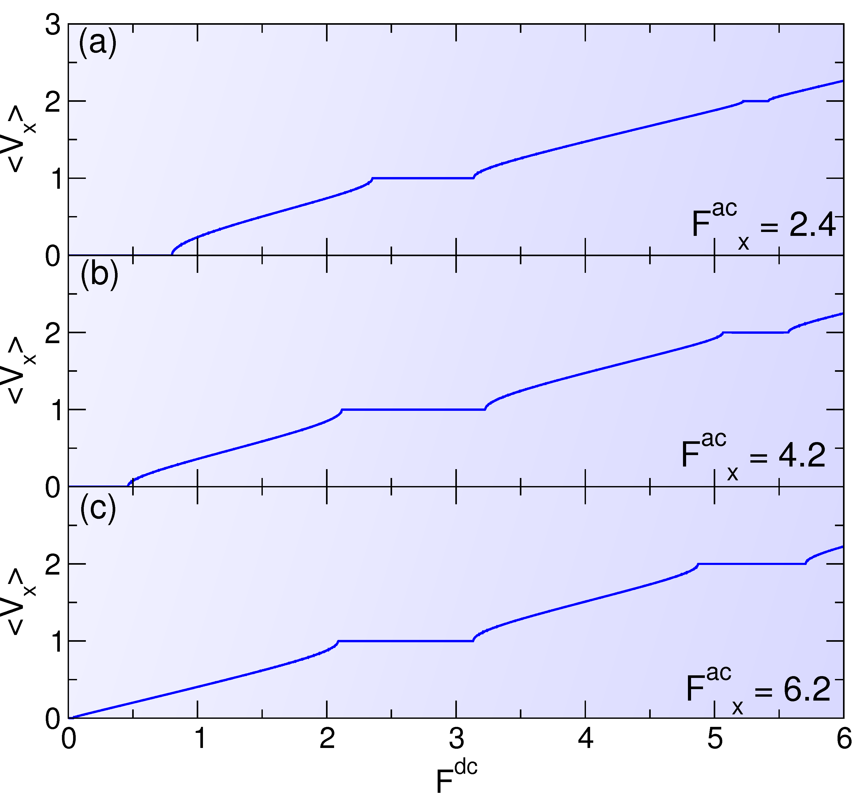
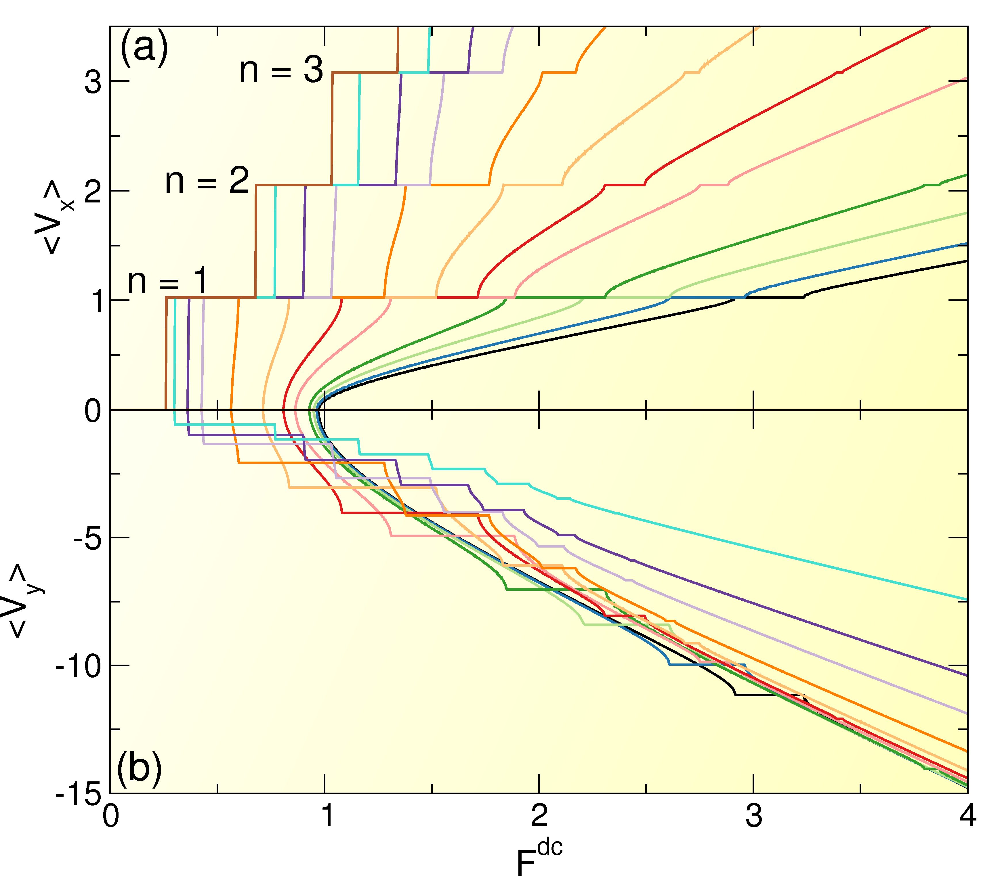
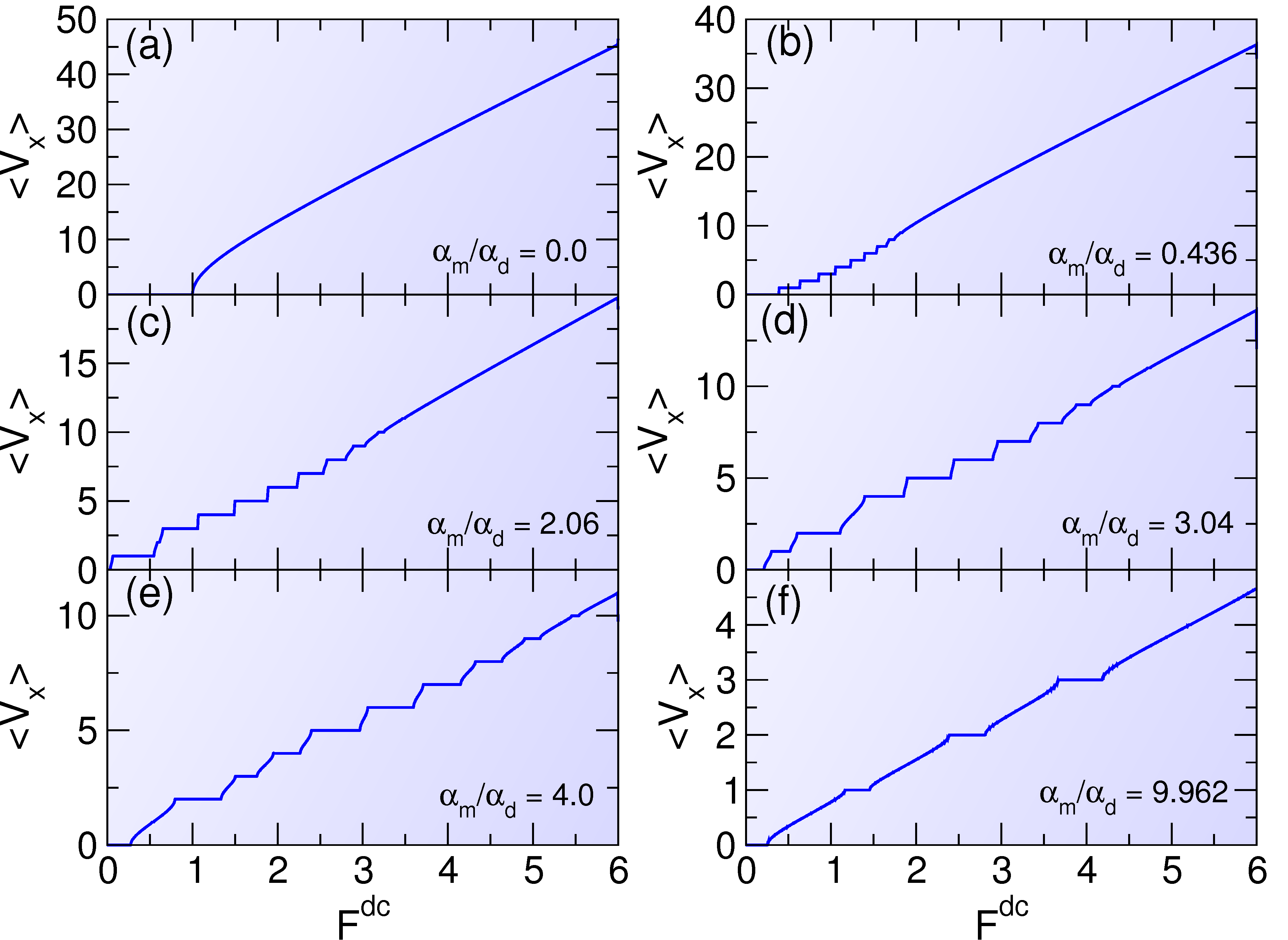
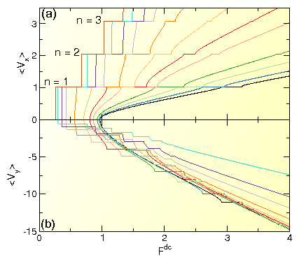
Physical Review B 92, 224432 (2015)

Shapiro Steps for Skyrmion Motion on a Washboard Potential with Longitudinal and Transverse ac Drives

C. Reichhardt and C. J. Olson Reichhardt

Theoretical Division, Los Alamos National Laboratory, Los Alamos, New Mexico 87545, USA

(Received 10 July 2015; published 28 December 2015)

We numerically study the behavior of two-dimensional skyrmions in the presence of a quasi-one-dimensional sinusoidal substrate under the influence of externally applied dc and ac drives. In the overdamped limit, when both dc and ac drives are aligned in the longitudinal direction parallel to the direction of the substrate modulation, the velocity-force curves exhibit classic Shapiro step features when the frequency of the ac drive matches the washboard frequency that is dynamically generated by the motion of the skyrmions over the substrate, similar to previous observations in superconducting vortex systems. In the case of skyrmions, the additional contribution to the skyrmion motion from a non-dissipative Magnus force shifts the location of the locking steps to higher dc drives, and we find that the skyrmions move at an angle with respect to the direction of the dc drive. For a longitudinal dc drive and a perpendicular or transverse ac drive, the overdamped system exhibits no Shapiro steps; however, when a finite Magnus force is present we find pronounced transverse Shapiro steps along with complex two-dimensional periodic orbits of the skyrmions in the phase-locked regimes. Both the longitudinal and transverse ac drives produce locking steps whose widths oscillate with increasing ac drive amplitude. We examine the role of collective skyrmion interactions and find that additional fractional locking steps occur for both longitudinal and transverse ac drives. At higher skyrmion densities, the system undergoes a series of dynamical order-disorder transitions, with the skyrmions forming a moving solid on the phase locking steps and a fluctuating dynamical liquid in regimes between the steps.
I. INTRODUCTION
II. SIMULATION AND SYSTEM
III. LONGITUDINAL AC DRIVING
IV. TRANSVERSE AC DRIVING
A. Dependence on substrate strength and ac amplitude
V. COLLECTIVE EFFECTS
VI. SUMMARY
References

I.  INTRODUCTION

Phase locking or synchronization effects can arise in coupled oscillators when the different frequencies lock together over a certain range of parameter space, an effect that was first reported by Huygens for the synchronization of pendulum clocks [1]. Phase locking has been extensively studied for numerous dynamical systems ranging from a pair of coupled oscillators to an entire coupled oscillator array [2,3]. A single particle moving over a tilted one-dimensional washboard potential can also experience phase locking when an additional ac driving force is applied. The substrate periodicity produces intrinsic periodic modulations of the particle velocity in the absence of an ac drive which increase in frequency as the magnitude of the tilt or dc drive increases. Addition of an external fixed-frequency ac drive produces locking regimes in which the average dc velocity remains constant even as the magnitude of the dc drive is increased. The same picture can be applied to Josephson junctions, where the analog of a velocity-force curve is the voltage-current curve, which exhibits a series of phase locking regions called Shapiro steps under an applied ac drive for single junctions [4,5] and coupled arrays of junctions [6]. One of the hallmarks of Shapiro steps is that the step width oscillates as a function of the ac drive amplitude [4,5,6]. Shapiro step phenomena also arise in dc and ac driven charge density waves [7,8,9], spin density waves [10], and Frenkel-Kontorova models consisting of commensurate or incommensurate arrangements of particles moving over ordered or disordered substrates [11,12,13]. In the case of vortex motion in type-II superconductors, Martinoli et al. reported the first observation of Shapiro steps for dc and ac driven vortices interacting with a periodic one-dimensional (1D) substrate created by periodic thickness modulations of the sample [14,15], while similar effects were observed for vortices driven over 1D [16,17] or two-dimensional (2D) [18,19] periodic substrates. More recently, Shapiro steps have been found for ac and dc driven colloidal particles moving over a quasi-1D periodic substrate [20].
Shapiro steps can also occur when a lattice of collectively interacting particles moves over a random substrate under combined dc and ac drives. Here, the effective elastic coupling between the particles comprising the lattice generates an intrinsic washboard frequency that can lock to the applied ac driving frequency. Such steps have been studied for vortices moving over random disorder [21,22,23,24,25] or through confined channel geometries [26]. For particles confined to 2D and moving over a quasi-1D substrate, both the ac and dc drives must be applied in the same direction to produce Shapiro steps; however, for vortices moving over 2D periodic or egg-carton substrates, it is possible to obtain what are called transverse phase locking steps when the ac drive is perpendicular to the direction of the dc drive [27,28,29]. These phase locking steps are distinct from Shapiro steps, and their widths grow quadratically with increasing ac amplitude rather than showing the oscillatory behavior associated with Shapiro steps. Phase locking effects can also occur for overdamped particle motion in 2D periodic systems under combinations of two perpendicular ac drives, producing localized and delocalized motion as well as rectification effects [30,31,32,33,34,35].
In systems such as vortices and colloidal particles, an overdamped description of the equations of motion is appropriate. In contrast, the skyrmions that were recently discovered in chiral magnets have particle-like properties and many similarities to superconducting vortices, but have the important distinction that there is a strong non-dissipative Magnus force in their motion [36,37,38,39,40,41,42,43,44,45]. The skyrmions can be set into motion by an applied current and are observed to have a very small depinning threshold [38,39,40,41,46,47], in part because the effectiveness of the Magnus force can be up to ten times stronger than the dissipative force component. The Magnus force introduces a velocity component of the skyrmion that is perpendicular to the direction of an imposed external force, so a skyrmion deflects from or spirals around an attractive pinning site rather than moving directly toward the potential minimum as would occur for systems governed by overdamped dynamics [40,41,47,48,49,50,51]. Since skyrmions are particle-like objects, many of their dynamical properties can be captured using a point particle model based on a modified Theile's equation that takes into account repulsive skyrmion-skyrmion interactions, the Magnus force, damping, and substrate interactions [47,52]. Such an approach has been shown to match well with micromagnetic modeling [47] of the depinning of skyrmions in periodic [48] and random pinning arrays [49]. Particle-based skyrmion models were used to describe the motion of skyrmions interacting with single pinning sites [50,51] as well as skyrmion motion in confined regions [53]. Since skyrmions can easily be driven with an applied external drive they potentially open a new class of experimentally accessible dynamical systems where the Magnus force has a dominant effect. It should be possible to create various types of potential energy landscapes for skyrmions through techniques such as thickness modulations, periodic applied stain, controlled irradiation, or spatially periodic doping. An open question is how known phase locking phenomena would be affected by the inclusion of a Magnus force, and whether new types of phase locking effects might appear that are absent in overdamped systems. Skyrmions also have potential for various spintronic applications [54] which would require the skyrmions to move in a controlled manner, so an understanding of skyrmion phase locking dynamics could be useful for producing new methods for precision control of skyrmion motion.
Fig1.png
Figure 1: (Color online) Skyrmions (red dots) at a density of ρs=0.001 on a periodic quasi-1D substrate with Ap=1.0. The darker regions are potential maxima and the lighter regions are potential minima, while lines indicate the skyrmion trajectories. (a) For an ac drive Facx=1.0 applied in the longitudinal or x-direction at αmd = 1.0 and Fdc=0, the skyrmions oscillate in 1D paths at a 45° angle to the x axis. (b) For an ac drive Facy=0.75 applied in the transverse or y-direction with Fdc=0 at αmd = 0.0 or the overdamped limit, the skyrmions move in 1D paths along the y direction. (c) The same as in (b) with αmd = 1.0, where the skyrmions form elliptical 2D counterclockwise orbits.
In this work we examine Shapiro steps for skyrmions moving over a quasi-1D periodic washboard substrate. In Section II we describe the system geometry and simulation details for our model of individual and collectively interacting skyrmions driven over a periodic substrate, as illustrated in Fig. 1. In Section III we examine longitudinal Shapiro steps for a single skyrmion subjected to superimposed dc and ac driving forces applied along the direction of the substrate periodicity, and find that increasing the magnitude of the Magnus term generates an increasing skyrmion velocity component in the direction transverse to the driving direction and gradually shifts the Shapiro steps to higher values of the dc drive. In Section IV we examine Shapiro steps for individual skyrmions when the ac drive is applied perpendicular to the dc drive and the substrate periodicity direction. In this geometry, Shapiro steps are absent in the overdamped limit; however, when there is a finite Magnus term, then what we term Magnus-induced Shapiro steps can occur. On the steps, the skyrmion follows periodic 2D orbits, and the number of observable steps increases as the Magnus term increases. In Section IVa we show that as the strength of the substrate increases, the transitions between the step and nonstep regions become sharper. In Section V we examine collectively interacting skyrmions for a dc drives applied parallel to the substrate periodicity direction combined with a parallel or perpendicular ac drive, and find that both the longitudinal and transverse Shapiro step phenomena are robust. We also show that the skyrmion lattice is much more ordered on the Shapiro steps, while outside of the steps the skyrmion lattice is disordered. In Section VI we summarize our results.

II.  SIMULATION AND SYSTEM

We consider a 2D system of size L ×L with periodic boundary conditions in the x and y directions containing Ns skyrmions at a density of ρs=Ns/L2. Single (Ns=1) or multiple skyrmions interact with a quasi-1D periodic sinusoidal potential with a periodicity direction running along the x direction, as illustrated in Fig. 1. The equation of motion for a single skyrmion i with velocity vi=dri/dt moving in the xy plane is
αdvi + αm
^
z
 
×vi = Fssi + Fspi + Fdc + Fac .
(1)
Here ri is the location of the skyrmion and αd is the prefactor of the damping force that aligns the skyrmion velocity in the direction of the net external forces. The second term is the Magnus force with prefactor αm, which rotates the velocity into the direction perpendicular to the net external forces. In order to maintain a constant magnitude of the skyrmion velocity we impose the constraint αd2 + α2m = 1 and vary the relative importance of the Magnus force to the damping force by changing the ratio αmd. In the overdamped limit αm = 0.0, while for skyrmions αmd can be ten or larger [41,47].
The skyrmion-skyrmion interaction force is Fssi = ∑j=1NsK1(Rij)rij where Rij = |rirj|, rij = (rirj)/Rij, and K1 is the modified Bessel function. This interaction is repulsive and falls off exponentially for large Rij. For most of this work we remain in the limit where skyrmion-skyrmion interactions are weak so that we can consider the dynamics of a single skyrmion; however, we show that most of our results are robust under the inclusion of skyrmion-skyrmion interactions. The substrate force Fspi = −∇U(xi) x arises from a washboard potential
U(x) = U0 cos(2πxi/a)
(2)
where xi=ri ·x, a is the periodicity of the substrate, and we define the substrate strength to be Ap = 2πU0/a. Unless otherwise noted, we take Ap=1.0. The dc driving term Fdc=Fdcx is slowly increased in magnitude to avoid any transient effects. The ac driving term is either Facx = Facxcos(ωt)x for longitudinal driving or Facy = Facycos(ωt)y for transverse driving.
We measure the time-averaged skyrmion velocities in the x direction 〈Vx 〉 = ∑i=1Ns2π〈vi ·x 〉/Nsωa and y-direction 〈Vy〉 = ∑i=1Ns2π〈vi ·y 〉/Nsωa. Here, due to the periodicity of the substrate, phase locked steps occur when the skyrmions travel integer multiples of the substrate periodicity na during each ac drive cycle, allowing us to label the steps n = 0 for the pinned phase and n = 1, 2... for the higher order steps. We focus on the two ac frequencies ω = 8×10⁻⁴ inverse simulation time steps for the longitudinal ac driving and ω = 1.6×10⁻³ inverse simulation time steps for the transverse ac driving, and use a substrate lattice constant of a = 3.272.
We use two different driving protocols as illustrated in Fig. 1. For longitudinal driving, we have
Fdrive = Fdc
^
x
 
+ Facxcos(ωt)
^
x
 
,
(3)
corresponding to the conditions under which Shapiro steps arise for an overdamped system. For transverse driving, we have
Fdrive = Fdc
^
x
 
+ Facycos(ωt)
^
y
 
,
(4)
which would produce no Shapiro steps in the overdamped limit. Experimentally, skyrmion motion can be induced by applying a spin-polarized current, so the drive geometry we describe here can be produced by applying a dc current to the sample along the substrate periodicity direction and superimposing a parallel or perpendicular ac current, similar to parallel or crossed current studies performed in vortex systems.
In Fig. 1(a) we show the skyrmion trajectories for Facx = 1.0, Fdc = 0.0, αmd = 1.0, and a skyrmion density of ρs=0.001. In this case the skyrmions are pinned and form a triangular lattice that is commensurate with the substrate. The ac drive causes the skyrmions to oscillate in the potential minima; however, their motion is not strictly in the x-direction but is tilted at an angle of θ = 45° with respect to the x direction due to the Magnus force, which induces a velocity component perpendicular to the ac driving direction. In the absence of a substrate, a dc or ac drive applied in the x-direction causes the skyrmions to move at an angle θ = arctan(αmd) with respect to the driving direction, so that in the overdamped limit of αm = 0.0 the skyrmion moves parallel to the direction of the net external driving force. In Fig. 1(b), we rotate the direction of the ac drive to be in the transverse direction with Facy=0.75 and Fdc=0 for a sample with αmd = 0.0. In this case the skyrmion motion follows strictly 1D paths aligned with the y-direction that pass through the potential minima of the substrate. For αmd = 1.0, as shown in Fig. 1(c), the skyrmions rotate in counterclockwise elliptical patterns, showing that the Magnus force can induce x-direction motion even when the drive is applied only in the y-direction. In the absence of the substrate the ac drive would produce only 1D trajectories at an angle with respect to the y-axis. This highlights the fact that the Magnus force affects how the skyrmions move when interacting with forces induced by the substrate.

III.  LONGITUDINAL AC DRIVING

Fig2.png
Figure 2: 〈Vx〉 (upper blue curves) and 〈Vy〉 (lower red curves) vs Fdc for the system in Fig. 1(a) in the single skyrmion limit at Facx = 1.0. (a) In the overdamped limit of αmd = 0, 〈Vy〉 = 0 and a series of steps appear in 〈Vx〉 indicating phase locking. (b) At αmd = 0.58, 〈Vy〉 is finite. (c) αmd = 3.042 and (d) αmd = 9.962 show the increase of skyrmion motion in the direction transverse to the substrate and the shift in the locking phases.
We first consider the case illustrated in Fig. 1(a) of ac driving in the longitudinal direction. We conduct a series of simulations for increasing αmd and focus on the single skyrmion limit. In general we find that the Shapiro steps we observe remain robust when finite skyrmion-skyrmion interactions are included; however, additional features can arise for varied fillings when the skyrmion structure is incommensurate with the substrate, as we discuss in Section V. In Fig. 2(a) we plot 〈Vx〉 and 〈Vy〉 versus Fdc for the system in Fig. 1(a) at Facx = 1.0 in the overdamped limit of αmd = 0. Here 〈Vy〉 = 0 while 〈Vx〉 shows a series of steps indicative of the phase locking. These features are similar to those observed for other overdamped systems moving over quasi-1D periodic substrates such as vortices in type-II superconductors moving over quasi-1D substrate modulations. In Fig. 2(b), when αmd = 0.58, both 〈Vy〉 and 〈Vx〉 are finite and have a ratio of |〈Vy〉/〈Vx〉| ≈ 0.58. Here the phase locking is still occurring, but the intervals of Fdc in which the phase locking steps appear are shifted. Figure 2(c) shows that at αmd = 3.042, both |〈Vy〉| and some of the step widths have increased in size, and there are no clear regions between the steps where no phase locking is occurring. In Fig. 2(d), at αmd = 9.962, there is only a single phase locking step.
Fig3.png
Figure 3: (a) 〈Vx〉 vs Fdc at Ap = 1.0 for αmd = 0.0 (brown), 0.577 (light blue), 0.98 (dark purple), 1.33 (light purple), 2.06 (dark orange), 3.042 (light orange), 4.0 (dark red), 4.92 (light red), 7.0 (dark green), 8.407 (light green), 9.962 (dark blue), and 11.147 (black), from left to right. Here 〈Vx〉 exhibits quantized values corresponding to specific steps. (b) The corresponding values of 〈Vy〉 vs Fdc, which contains steps that are not quantized.
Fig4.png
Figure 4: The regions of phase locking for the n = 0 to n = 8 steps as a function of Fdc and αmd. The width of the steps is reduced and the steps shift to higher values of Fdc with increasing αmd.
To more clearly demonstrate the behavior of the steps for varied αmd, in Fig. 3(a) we plot 〈Vx〉 versus Fdc for αmd ranging from 0.0 to 11.147, with the evolution of the first three locking steps n=1 to 3 highlighted. For a given value of n, the step in 〈Vx〉 has a fixed value regardless of the choice of αmd, and each step shifts to higher values of Fdc with increasing αmd. The corresponding 〈Vy〉 versus Fdc plot in Fig. 3(b) shows that the steps in 〈Vy〉 are not quantized in integer multiples of 2π/aω. The quantization of the 〈Vx〉 arises from the periodicity of the substrate in the x-direction, and since the y-direction has no periodicity, there is no quantization of 〈Vy〉. In Fig. 4 we highlight the evolution of the widths of the n = 0 through n=8 steps as a function of Fdc and αmd at Facx = 1.0. At αmd = 0, the largest number of phase locking steps can be resolved. We observe two general trends as αmd increases. First, for n > 3, the widths of the locking regions decrease and the intervals of Fdc over which the locking occurs shift to higher values of Fdc, with the magnitude of this shift increasing with increasing n. Second, the width of the n = 1, 2, and 3 steps initially increases for increasing αmd before reaching a maximum and then decreasing again. The width of the n = 0 step reaches a maximum with increasing αmd and then saturates. The shift in the locations of the phase locking regions arises because the angle at which the skyrmions move with respect to the x-axis increases with increasing αmd, causing the skyrmions to spend larger intervals of time interacting with the repulsive portion of the substrate potential. As a result, higher values of Fdc must be applied to cause the skyrmion to translate in the x-direction at larger αmd.
Fig5.png
Figure 5: 〈Vx〉 vs Fdc for αmd = 9.962. (a) Facx = 2.4. (b) Facx=4.2. (c) Facx=6.2.
Fig6.png
Figure 6: (a) The width ∆0 of the n = 0 step vs Facx for the system in Fig. 5 at αmd = 9.962. The solid line is a fit to the |J0| Bessel function. (b) The width ∆1 of the n=1 step vs Facx for the same system. The solid line is a fit to the |J1| Bessel function. In each case the width of step n shows an oscillation of the form of the Bessel function |Jn(Facx)|, which is characteristic of Shapiro step phase locking.
We next determine if the phase locking steps at high Magnus force prefactor are of the Shapiro type. In Fig. 5 we plot 〈Vx〉 versus Fdc for αmd = 9.962 at Facx = 2.4, 4.2, and 6.2 to show the variation in the widths of the n = 0, n=1, and n=2 steps. In Fig. 6 we plot the widths ∆0 and ∆1 of the n=0 and n=1 steps, respectively, versus Facx. Each step shows the characteristic oscillation expected for Shapiro steps, where the width of step n is proportional to |Jn(Facx)|, where Jn is the nth-order Bessel function [5]. The solid lines in Fig. 6(a,b) are fits to |J0| and |J1|, respectively. The higher order steps obey similar fits. This indicates that in the Magnus-dominated limit, Shapiro step phase locking is occurring.

IV.  TRANSVERSE AC DRIVING

Fig7.png
Figure 7: 〈Vx〉 vs Fdc for a system with dc driving in the x-direction and ac driving Facy = 1.0 in the y-direction. (a) At αmd = 0.0, there are no steps in 〈Vx〉. (b) At αmd = 0.436, steps are present. (c) αmd = 2.06. (d) αmd = 3.04. (e) αmd = 4.0. (f) αmd = 9.962.
We next consider the case illustrated in Fig. 1(b,c), where the ac drive is applied transverse to the direction of the substrate potential. In the overdamped limit of αmd = 0, such a drive causes the skyrmion to oscillate in the y-direction as shown in Fig. 1(b), and when a finite dc drive is applied in the longitudinal direction, a single washboard oscillation frequency in the x-direction is generated by the motion of the skyrmion over the periodic substrate. Since only one frequency is present, there is no coupling between two frequencies, so mode locking does not occur. When the Magnus force is finite, the transverse ac drive induces an oscillating velocity component in the longitudinal or x-direction as well as in the y-direction, as illustrated in Fig. 1(c), so that it is possible for the dc-induced washboard frequency to couple to the transverse ac frequency and generate a transverse Shapiro step. In Fig. 7 we plot 〈Vx〉 vs Fdc for a single skyrmion moving with Facy = 1.0. At αmd=0, shown in Fig. 7(a), there are no steps in 〈Vx〉, indicating the lack of phase locking, while the corresponding 〈Vy〉 = 0. Depinning occurs at the threshold value Fc of Fc = Ap = 1.0. Figure 7(b) shows that at αmd = 0.436, the depinning threshold has dropped substantially to Fc = 0.4 and a series of steps are now visible for 0.4 < Fdc < 2.0, indicating that phase locking is occurring. For αmd > 0.0, 〈Vy〉 is finite and the |〈Vy〉| versus Fdc curve has exactly the same form as 〈Vx〉 versus Fdc, but the magnitude of |〈Vy〉| is multiplied by αmd. In Fig. 7(c,d) we plot 〈Vx〉 versus Fdc for samples with αmd = 2.06 and 3.04, respectively. Here, the widths of the locking steps increase with increasing αmd and the step locations are shifted to higher values of Fdc. In samples with αmd = 4.0 and 9.962, as shown in Fig. 7(e,f), respectively, the steps extend out to larger values of Fdc, and the non-phase locking regions between the steps are also extended. The steps in 〈Vx 〉 once again occur at quantized values of n aω/2π due to the periodicity in the x-direction, while the steps in 〈Vy〉 do not have quantized values.
Fig8.png
Figure 8: The location of the upper edge of the n = 0 step as a function of Fdc and αmd for the system in Fig. 6 with a transverse ac drive of Facy = 1.0. Here there are several local minima and maxima that are associated with changes in the skyrmion orbits, as shown in Fig. 9 at the points marked a-d.
In Fig. 8 we plot the location of the upper edge of the n=0 step as a function of Fdc and αmd for the system shown in Fig. 6 with Ap=1.0. This is equivalent to the threshold depinning force Fc. Here Fdc/Ap=1.0 at αmd = 0.0 and it decreases to zero at αmd = 1.226. There is a local maximum in Fdc/Ap at αmd = 1.55, followed by another minimum near αmd = 2.2 and a broad plateau for higher values of αmd. This oscillatory behavior in the n = 0 step width is absent for longitudinal ac driving, as shown in Fig. 5 where Fc exhibits only monotonic behavior. The dips and maxima in Fc for the transverse ac driving are associated with transitions in the shape of the skyrmion orbits during a single ac drive cycle for increasing αmd.
Fig9.png
Figure 9: Skyrmions (red dots), potential maxima (darker regions), potential minima (lighter regions), and skyrmion trajectories (lines) in a portion of the system in Fig. 8 along the n = 0 step at the points labeled (a-d) in Fig. 8. (a) At αmd = 0.0 for Fdc = 0.1, there is 1D motion in the y-direction. (b) αmd = 0.75 at Fdc = 0.2. (c) At αmd = 1.54 and Fdc = 0.1, the skyrmion moves between two potential minima. (d) At αmd = 4.92 and Fdc=0.2, the skyrmion moves between three potential minima.
In Fig. 9 we illustrate the skyrmion trajectories in a subsection of the system on the n = 0 step at the points labeled (a-d) in Fig. 8. Figure 9(a) shows that for αmd = 0 and Fdc = 0.1, the skyrmion moves in a 1D path in the y-direction along the potential minimum. At αmd = 0.75 and Fdc = 0.2, in Fig. 9(b), the skyrmion forms an elliptical orbit that is confined within a single potential trough. On the local maximum in the n=0 step marked point c in Fig. 8, at αmd = 1.54 and Fdc = 0.1, Fig. 9(c) shows that the skyrmion forms a more complicated 2D orbit that has three lobes. In a single ac drive cycle the skyrmion translates back and forth by two substrate lattice constants. The dip in Fc at αmd = 1.226 shown in Fig. 8 corresponds to the point at which the skyrmion orbit transitions from being confined in one potential minimum to traversing two potential minima. Above the second local minimum at αmd = 2.2 in Fig. 8, the skyrmion orbit becomes even more complex, as illustrated in Fig. 9(d) for αmd = 4.92 and Fdc = 0.2. The skyrmion now moves between three substrate potential minima in a single ac drive cycle. The local minimum in the n = 0 step width at αmd = 2.2 then corresponds to the transition in the skyrmion motion from traversing two substrate minima to traversing three substrate minima. For higher values of αmd, additional minima in Fc could occur that would be correlated with orbits traversing four or more substrate minima. We expect that additional substrate minima would be resolvable in samples with a smaller substrate lattice constant a.
Fig10.png
Figure 10: (a) Evolution of the regions in which the n = 0, 1, 2, 3, 4, 5, 6, 7, 8, 9, 10, and 11 steps (from bottom to top) appear as a function of Fdc and αmd for Facy = 1.0. Increasing the Magnus force produces enhanced phase locking. (b) A blowup of panel (a) in the region of small αmd showing that the steps vanish as αmd goes to zero.
Fig11.png
Figure 11: Skyrmions (red dots), potential maxima (darker regions), potential minima (lighter regions), and skyrmion trajectories (lines) for the system in Fig. 9. (a) n = 1 orbit at αmd = 0.75 and Fdc = 0.6. (b) n = 2 orbit at αmd = 0.75 and Fdc = 0.7. (c) n = 2 orbit at αmd = 1.55 and Fdc = 0.5. (d) n = 1 orbit at αmd = 2.06 and Fdc = 0.3. Here the skyrmion translates by 2a in the positive x direction followed by a in the negative x direction for a net transport by a distance a in the x-direction during each ac cycle. (e) n = 3 orbit at αmd = 2.06 and Fdc = 0.67. (f) n = 1 orbit at αmd = 5.92 and Fdc = 0.67.
In Fig. 10(a) we highlight the regions of phase locking as a function of Fdc and αmd for steps n=0 through n=11 for the system in Fig. 7. When αmd = 0, all the steps with n ≥ 1 vanish, as illustrated in Fig. 10(b) where we plot the regime 0 ≤ αmd ≤ 1.0. As the Magnus force increases, a larger number of steps can be resolved. In general, the step widths increase with increasing αmd; however, certain steps such as n = 1, 2, and 3 show step width oscillations. In the case of longitudinal ac driving, the skyrmion orbits along the different locking steps are always 1D in nature. In contrast, the orbits are much more complicated for transverse ac driving. In Fig. 11(a) we show the n = 1 skyrmion orbit from Fig. 10 at αmd = 0.75 and Fdc = 0.6. The skyrmion translates in the positive x-direction and negative y-direction, making an angle close to θ = arctan(αmd) = 36.9° with the x-axis. During a single orbit the skyrmion passes through a loop and translates by one lattice constant in the x-direction. Figure 11(b) illustrates the n=2 orbit for αmd = 0.75 at Fdc = 0.7, where the skyrmion translates two lattice constants in the x-direction per ac cycle. On the n=2 step for αmd = 1.55, and Fdc = 0.5, shown in Fig. 11(c), the skyrmion moves at a steeper angle of θ = 57.1° from the x-axis. In Fig. 11(d), which shows the n = 1 orbit at αmd = 2.06 and Fdc = 0.3, during a single ac drive cycle the skyrmion initially moves 2a in the positive x-direction before moving a in the negative x-direction, producing a net translation in the x-direction of a distance a per ac cycle. Figure 11(e) shows the αmd = 2.06 system in the n = 3 orbit at Fdc = 0.67, where the skyrmion translates by 3a in a single ac cycle. On the n=1 step at αmd = 4.92 and Fdc = 0.67, plotted in Fig. 11(f), the skyrmion moves 3a in the positive x-direction during the first portion of the ac drive cycle followed by 2a in the negative x-direction during the second portion of the ac drive cycle, producing a net translation of a in the x direction during a single ac cycle. We observe similar orbits for the other values of n, and find that the net angle of the skyrmion motion with respect to the x axis increases with increasing αmd.

A.  Dependence on substrate strength and ac amplitude

Fig12.png
Figure 12: (a) 〈Vx〉 vs Fdc for Facy = 1.0, αmd = 9.962, and Ap = 0.5 (black), 2.0 (green), 4.0 (blue), and 7.0 (red). (b) The evolution of the n=0, 1, 2, and 3 step widths as a function of Fdc and Ap for the system in panel (a).
We next consider the effect of the substrate strength on the transverse locking steps at αmd = 9.962 and Facy = 1.0. In Fig. 12(a) we plot 〈Vx 〉 versus Fdc for Ap = 0.5, 2.0, 4.0, and 7.0. At the lower values of Ap, the phase locking steps decrease in width, and the steps completely vanish when Ap = 0. This is highlighted in Fig. 12(b) where we plot the widths of the n = 0, 1, 2, and 3 steps as a function of Fdc and Ap. The width of the locking regions oscillates with increasing Ap, and for Ap > 8.0 all the locking phases shift linearly to higher values of Fdc with increasing Ap. The step width oscillations arise due to variations in the number of potential minima through which the skyrmion orbit passes during a single ac drive cycle, similar to what was observed for fixed Ap and varied αmd. This result shows that the transverse phase locking is a generic feature that appears in both the strong and weak substrate regimes, and that it is more pronounced for stronger substrates.
Fig13.png
Figure 13: (a) The width ∆0 of the n = 0 step vs Facy for the system in Fig. 12 at αmd=9.962 and Ap=1.0. The solid line is a fit to the |J0| Bessel function. (b) The width ∆1 of the n=1 step vs Facy for the same system. The solid line is a fit to the |J1| Bessel function.
We next examine the dependence of the step widths at a fixed Ap on the ac driving amplitudes, as shown in Fig. 13 where we plot ∆0 and ∆1 versus Facy for Ap = 1.0 and αmd = 9.962. The solid lines are fits to ∆n ∝ |Jn(Facy)|, indicating that the transverse phase locking steps are also of the Shapiro step type, similar to the longitudinal phase locking steps.

V.  COLLECTIVE EFFECTS

Fig14.png
Figure 14: 〈Vx〉 vs Fdc at αmd = 2.0. (a) ac driving in the x-direction with Facx = 1.0 for a single skyrmion (dark blue line) and a sample containing multiple skyrmions at a density of ρs=0.04 (light orange line), showing that fractional phase locking steps can arise. (b) The same for ac driving in the y-direction at Facy=1.0.
We next consider assemblies of interacting skyrmions for the system shown in Fig. 1. In general, when the skyrmion density is commensurate with the substrate and the skyrmions can form a triangular lattice, skyrmion-skyrmion interactions cancel and we find the same types of phase locking observed in the single skyrmion systems. For incommensurate fillings where dislocations are present or when the skyrmion structure becomes distorted or anisotropic in the pinned phase, we find that it is possible for additional fractional phase locking to occur between the integer phase locking steps. These fractional locking steps occur when a portion of the skyrmions are locked to step n and the remainder of the skyrmions are locked to step n−1. In Fig. 14(a) we plot 〈Vx〉 versus Fdc for a system with ac driving in the x-direction at αmd = 2.06 and Facx = 1.0 to compare the results for a single skyrmion with a system at a skyrmion density of ρs=0.04. There are no fractional steps in the single skyrmion system; however, when interacting skyrmions are present we find fractional steps n/m, where n and m are integers. Figure 14(b) shows the same system for ac driving in the y-direction, where the same types of fractional steps arise. The fractional steps appear at incommensurate fields when it is possible to have two effective particle species in the system. One species is commensurate and the other is associated with interstitials, dislocations, or vacancies. In overdamped systems such as superconducting vortices moving over 2D periodic substrates, similar integer steps for individual or non-interacting vortices appear at commensurate matching fillings while additional fractional locking steps arise at non-matching fields [19].
At much higher skyrmion densities and for sufficiently strong substrate strengths, the pinned skyrmion structures become highly anisotropic due to the confinement in the 1D pinning rows. In the moving phase just above depinning, the effectiveness of the pinning is partially reduced and the repulsive skyrmion-skyrmion interactions favor a more uniform structure. The competition between skyrmion-skyrmion and skyrmion-substrate interactions produces a series of order-disorder transitions in the moving state. On the phase-locked steps, the skyrmions form an ordered moving anisotropic lattice and travel in a synchronized fashion, while between the phase locking steps the skyrmions adopt a more isotropic or liquid like configuration.
Fig15.png
Figure 15: (a) 〈Vx〉 vs Fdc at Facy = 1.0 and αmd = 2.06 for a sample with a skyrmion density of ρs=0.4. (b) The fraction of six-fold coordinated particles P6 vs Fdc for the same system showing that along the phase-locked steps the skyrmions form a much more ordered state.
Fig16.png
Figure 16: (a,c,e) The real space positions of the skyrmions from Fig. 15 and (b,d,f) the corresponding structure factors S(k). (a,b) The n = 1 phase locked step at Fdc = 0.25 from the point labeled a in Fig. 15(a) shows a partially ordered anisotropic structure. (c,d) On the non-step region at Fdc=0.6 labeled b in Fig. 15(a), the skyrmions form a disordered liquid like structure. (e,f) On a non-step region at Fdc = 9.0, the system forms a moving lattice.
In Fig. 15(a) we plot 〈Vx〉 versus Fdc for a sample with Facy = 1.0, αmd = 2.06, and a skyrmion density of ρs=0.4, showing the n=1, 3, and 4 phase locking steps. Figure 15(b) illustrates the corresponding fraction of six-fold coordinated skyrmions P6=Ns−1i=1Nsδ(6−zi), where zi is the coordination number of skyrmion i obtained from a Voronoi construction. On the phase locking steps, P6 increases to P6=0.92, while between the steps P6 ≈ 0.5 on average and shows strong fluctuations. In Fig. 16(a,b) we show the real space locations of the skyrmions and the corresponding structure factor S(k) on the n = 1 step at Fdc = 0.25 from Fig. 15. The skyrmions are all moving together and form a partially ordered but anisotropic lattice. Even though the system is anisotropic, most of the skyrmions have six neighbors, so that P6 ≈ 0.9. Figure 16(c,d) shows the same sample at Fdc = 0.6, corresponding to the non-phase locking region labeled b in Fig. 15. Here the skyrmions form a disordered structure that is less anisotropic than the phase locked state. We observe similar sets of dynamical order-disorder transitions between step and non-step regions for increasing Fdc and find similar effects for ac driving in the x-direction. Studies in overdamped systems of collections of interacting vortices also show that the vortices are more ordered and exhibit suppressed noise fluctuations in a phase locked region [23,25]. At higher Fdc, the effectiveness of the substrate gradually diminishes, the phase locking steps disappear, and the skyrmions can reorder into a more uniform moving crystal state as shown in Fig. 16(e,f) at Fdc = 9.0. Similar dynamical reordering to a triangular lattice for high drives has been observed for skyrmions interacting with random pinning [49] as well as for vortices driven over random pinning arrays [55,56]. The vortex lattice normally aligns with the driving current when the dynamical reordering occurs on a random pinning array [23,2,55,56,57,58,59] or a quasi-1D pinning array [60,61]. In contrast, Figure 16 indicates that the skyrmion lattice remains aligned with the substrate troughs along the y direction even though the dc drive is applied along the x direction. This results from a channeling effect caused when the skyrmions flow at an angle to the applied dc drive due to the Magnus term. Since the skyrmions enter each substrate trough at an angle instead of perpendicularly, the quasi-1D substrate channels their motion along the y direction, similar to the flow that can occur for overdamped vortices interacting with a line defect such as a twin boundary [62]. As a result, the dynamically reordered skyrmion lattice is oriented perpendicular to the dc driving direction.
These results show that Shapiro steps for skyrmions interacting with a periodic substrate are a robust feature that occurs for a variety of skyrmion densities and substrate strengths. The change in the skyrmion lattice structure as the system passes in and out of phase locked states as a driving current is swept could be observed using neutron scattering or noise measurements.

VI.  SUMMARY

We have analyzed Shapiro steps for skyrmions interacting with periodic quasi-one-dimensional substrates in the presence of combined dc and ac drives, with a specific focus on the role of the Magnus force in the dynamics. When the dc and ac drives are both applied in the longitudinal direction, which is aligned with the substrate periodicity, phase locking occurs, and as the role of the Magnus force increases, the phase locking steps gradually reduce in width and shift to higher values of the driving force. The skyrmions move at an angle to the direction of the external dc drive that increases as the contribution of the Magnus force increases. When the ac drive is applied perpendicular to the dc drive and the substrate periodicity direction, there is no phase locking in the overdamped limit; however, when there is a finite Magnus force, phase locking can occur. On the phase locked steps the skyrmions move in intricate two-dimensional periodic orbits. We map out the evolution of the phase locked regions for the transverse and longitudinal ac driving for varied contribution of the Magnus force, ac driving amplitudes, and substrate strength. When collective interactions between skyrmions are introduced, fractional Shapiro steps can appear. For strong substrate strengths and higher skyrmion densities, both longitudinal and transverse phase locking steps occur that are associated with dynamically induced transitions between an ordered anisotropic solid on the steps to a fluctuating liquid state in the non-phase locked regimes. Such transitions could be observed with neutron scattering.

ACKNOWLEDGMENTS

This work was carried out under the auspices of the NNSA of the U.S. DoE at LANL under Contract No. DE-AC52-06NA25396.

References

[1]
M. Bennett, M.F. Schatz, H. Rockwood, and K. Wiesenfeld, Huygen's clocks, Proc. Roy. Soc. A 458, 563 (2002).
[2]
E. Ott, Chaos (Cambridge, New York, 1993).
[3]
A. Pikovsky, M. Rosenblum, and J. Kurths, Synchronization: A Universal Concept in Nonlinear Sciences (Cambridge Univ. Press, Cambridge, 2001).
[4]
S. Shapiro, Josephson currents in superconducting tunneling: the effect of microwaves and other observations, Phys. Rev. Lett. 11, 80 (1963).
[5]
A. Barone and G. Paterno, Physics and Applications of the Josephson Effect (Wiley, New York, 1982).
[6]
S. P. Benz, M. S. Rzchowski, M. Tinkham, and C. J. Lobb, Fractional giant Shapiro steps and spatially correlated phase motion in 2D Josephson arrays, Phys. Rev. Lett. 64, 693 (1990); D. Domínguez and J. V. José, Giant Shapiro steps with screening currents, Phys. Rev. Lett. 69, 514 (1992).
[7]
S. N. Coppersmith and P. B. Littlewood, Interference phenomena and mode locking in the model of deformable sliding charge-density waves, Phys. Rev. Lett. 57, 1927 (1986).
[8]
G. Grüner, The dynamics of charge-density waves, Rev. Mod. Phys. 60, 1129 (1988).
[9]
R. E. Thorne, J. S. Hubacek, W. G. Lyons, J. W. Lyding, and J. R. Tucker, ac-dc interference, complete mode locking, and origin of coherent oscillations in sliding charge-density-wave systems, Phys. Rev. B 37, 10055 (1988).
[10]
G. Kriza, G. Quirion, O. Traetteberg, W. Kang, and D. Jérome, Shapiro interference in a spin-density-wave system, Phys. Rev. Lett. 66, 1922 (1991).
[11]
B. Hu and J. Tekic, Amplitude and frequency dependence of the Shapiro steps in the dc- and ac-driven overdamped Frenkel-Kontorova model, Phys. Rev. E 75, 056608 (2007); J. Tekic and B. Hu, Noise-induced Bessel-like oscillations of Shapiro steps with the period of the ac force, Phys. Rev. B 78, 104305 (2008).
[12]
C. Thomas and A. Middleton, Irrational mode locking in quasiperiodic systems, Phys. Rev. Lett. 98, 148001 (2007).
[13]
O.M. Braun and Y.S. Kivshar, The Frenkel-Kontorova Model: Concepts, Methods, and Applications (Springer-Verlag, Berlin Heidelberg, 2010).
[14]
P. Martinoli, O. Daldini, C. Leemann, and E. Stocker, A.C. quantum interference in superconducting films with periodically modulated thickness, Solid State Commun. 17, 205 (1975).
[15]
P. Martinoli, O. Daldini, C. Leemann, and B. Van den Brandt, Josephson oscillation of a moving vortex lattice, Phys. Rev. Lett. 36, 382 (1976).
[16]
P. Martinoli, Static and dynamic interaction of superconducting vortices with a periodic pinning potential, Phys. Rev. B 17, 1175 (1978).
[17]
O.V. Dobrovolskiy, AC quantum interference effects in nanopatterned Nb microstrips, J. Supercond. Novel Mag. 28, 469 (2015).
[18]
L. Van Look, E. Rosseel, M.J. Van Bael, K. Temst, V.V. Moshchalkov, and Y. Bruynseraede, Shapiro steps in a superconducting film with an antidot lattice, Phys. Rev. B 60, R6998(R) (1999).
[19]
C. Reichhardt, R.T. Scalettar, G.T. Zimányi, and N. Grønbech-Jensen, Phase-locking of vortex lattices interacting with periodic pinning, Phys. Rev. B 61, R11914(R) (2000).
[20]
M.P.N. Juniper, A.V. Straube, R. Besseling, D.G.A.L. Aarts, and R.P.A. Dullens, Microscopic dynamics of synchronization in driven colloids, Nature Commun 6, 7187 (2015).
[21]
A. T. Fiory, Interference effects in a superconducting aluminum film: vortex structure and interactions, Phys. Rev. B 7, 1881 (1973).
[22]
J. Harris, N. Ong, R. Gagnon, and L. Taillefer, Washboard frequency of the moving vortex lattice in YBa2Cu3O6.93 detected by ac-dc interference, Phys. Rev. Lett. 74, 3684 (1995).
[23]
A.B. Kolton, D. Domínguez, and N. Grønbech-Jensen, Mode locking in ac-driven vortex lattices with random pinning, Phys. Rev. Lett. 86, 4112 (2001).
[24]
N. Kokubo, K. Kadowaki, and K. Takita, Peak effect and dynamic melting of vortex matter in NbSe2 crystals, Phys. Rev. Lett. 95, 177005 (2005).
[25]
S. Okuma, J. Inoue, and N. Kokubo, Suppression of broadband noise at mode locking in driven vortex matter, Phys. Rev. B 76, 172503 (2007).
[26]
N. Kokubo, R. Besselilng, V.M. Vinokur, and P.H. Kes, Mode locking of vortex matter driven through mesoscopic channels. Phys. Rev. Lett. 88, 247004 (2002).
[27]
C. Reichhardt, A.B. Kolton, D. Domínguez, and N. Grønbech-Jensen, Phase-locking of driven vortex lattices with transverse ac force and periodic pinning, Phys. Rev. B 64, 134508 (2001).
[28]
C. Reichhardt and C. J. Olson, Transverse phase locking for vortex motion in square and triangular pinning arrays, Phys. Rev. B 65, 174523 (2002).
[29]
V.I. Marconi, A.B. Kolton, D. Domínguez, and N. Grønbech-Jensen, Transverse phase locking in fully frustrated Josephson junction arrays: a different type of fractional giant steps, Phys. Rev. B 68, 104521 (2003).
[30]
C. Reichhardt, C. J. Olson, and M. B. Hastings, Rectification and phase locking for particles on symmetric two-dimensional periodic substrates, Phys. Rev. Lett. 89, 024101 (2002).
[31]
C. Reichhardt and C. J. Olson Reichhardt, Absolute transverse mobility and ratchet effect on periodic two-dimensional symmetric substrates, Phys. Rev. E 68, 046102 (2003).
[32]
P. Tierno, T. Johansen, and T. Fischer, Localized and delocalized motion of colloidal particles on a magnetic bubble lattice, Phys. Rev. Lett. 99, 038303 (2007).
[33]
D. Speer, R. Eichhorn, and P. Reimann, Directing Brownian motion on a periodic surface, Phys. Rev. Lett. 102, 124101 (2009).
[34]
J.M. Sancho and A.M. Lacasta, The rich phenomenology of Brownian particles in nonlinear potential landscapes, Eur. Phys. J. Spec. Top. 187, 49 (2010).
[35]
Y. Yang, W.-S. Duan, L. Yang, J.-M. Chen, and M.-M. Lin, Rectification and phase locking in overdamped two-dimensional Frenkel-Kontorova model, EPL 93, 16001 (2011).
[36]
S. Mühlbauer, B. Binz, F. Jonietz, C. Pfleiderer, A. Rosch, A. Neubauer, R. Georgii, and P. Böni, Skyrmion lattice in a chiral magnet, Science 323, 915 (2009).
[37]
X.Z. Yu, Y. Onose, N. Kanazawa, J.H. Park, J.H. Han, Y. Matsui, N. Nagaosa, and Y. Tokura, Real-space observation of a two-dimensional skyrmion crystal, Nature 465, 901 (2010).
[38]
T. Schulz, R. Ritz, A. Bauer, M. Halder, M. Wagner, C. Franz, C. Pfleiderer, K. Everschor, M. Garst, and A. Rosch, Emergent electrodynamics of skyrmions in a chiral magnet, Nature Phys. 8, 301 (2012).
[39]
X.Z. Yu, N. Kanazawa, W.Z. Zhang, T. Nagai, T. Hara, K. Kimoto, Y. Matsui, Y. Onose, and Y. Tokura, Skyrmion flow near room temperature in an ultralow current density, Nature Commun. 3, 988 (2012).
[40]
J. Iwasaki, M. Mochizuki, and N. Nagaosa, Universal current-velocity relation of skyrmion motion in chiral magnets, Nature Commun. 4, 1463 (2013).
[41]
N. Nagaosa and Y. Tokura, Topological properties and dynamics of magnetic skyrmions, Nature Nanotechnol. 8, 899 (2013).
[42]
S. Woo, K. Litzius, B. Krüger, M.-Y. Im, L. Caretta, K. Richter, M. Mann, A. Krone, R. Reeve, M. Weigand, P. Agrawal, P. Fischer, M. Kläui, G.S.D. Beach, Observation of room temperature magnetic skyrmions and their current-driven dynamics in ultrathin Co films, arXiv:1502.07376 (unpublished).
[43]
C. Moreau-Luchaire, C. Moutafis, N. Reyren, J. Sampaio, N. Van Horne, C.A.F. Vaz, K. Bouzehouane, K. Garcia, C. Deranlot, P. Warnicke, P. Wohlhüter, J.M. George, J. Raabe, V. Cros, and A. Fert, Skyrmions at room temperature: from magnetic thin films to magnetic multilayers, arXiv:1502.07853 (unpublished).
[44]
W. Jiang, P. Upadhyaya, W. Zhang, G. Yu, M.B. Jungfleisch, F.Y. Fradin, J.E. Pearson, Y. Tserkovnyak, K.L. Wang, O. Heinonen, S.G.E. te Velthuis, and A. Hoffmann, Blowing magnetic skyrmion bubbles, Science 349, 283 (2015).
[45]
Y. Tokunaga, X.Z. Yu, J. S. White, H. M. Rønnow, D. Morikawa, Y. Taguchi, and Y. Tokura, A new class of chiral materials hosting magnetic skyrmions beyond room temperature, Nature Commun. 6, 7638 (2015).
[46]
S.-Z. Lin, C. Reichhardt, C.D. Batista, and A. Saxena, Driven skyrmions and dynamical transitions in chiral magnets, Phys. Rev. Lett. 110, 207202 (2013).
[47]
S.-Z. Lin, C. Reichhardt, C.D. Batista, and A. Saxena, Particle model for skyrmions in metallic chiral magnets: Dynamics, pinning, and creep, Phys. Rev. B 87, 214419 (2013).
[48]
C. Reichhardt, D. Ray, and C. J. Olson Reichhardt, Quantized transport for a skyrmion moving on a two-dimensional periodic substrate, Phys. Rev. B 91, 104426 (2015).
[49]
C. Reichhardt, D. Ray, and C. J. Olson Reichhardt, Collective transport properties of driven skyrmions with random disorder, Phys. Rev. Lett. 114, 217202 (2015).
[50]
Y.-H. Liu and Y.-Q. Li, A mechanism to pin skyrmions in chiral magnets, J. Phys.: Condens. Matter 25, 076005 (2013).
[51]
J. Müller and A. Rosch, Capturing of a magnetic skyrmion with a hole, Phys. Rev. B 91, 054410 (2015).
[52]
A.A. Thiele, Steady-state motion of magnetic domains, Phys. Rev. Lett. 30, 230 (1973).
[53]
F. Büttner, C. Moutafis, M. Schneider, B. Krüger, C.M. Günther, J. Geilhufe, C. v. Korff Schmising, J. Mohanty, B. Pfau, S. Schaffert, A. Bisig, M. Foerster, T. Schulz, C.A.F. Vaz, J.H. Franken, H.J.M. Swagten, M. Kläui, and S. Eisebitt, Dynamics and inertia of skyrmionic spin structures, Nature Phys. 11, 225 (2015).
[54]
A. Fert, V. Cros, and J. Sampaio, Skyrmions on the track, Nature Nanotechnol. 8, 152 (2013).
[55]
C.J. Olson, C. Reichhardt, and F. Nori, Nonequilibrium dynamic phase diagram for vortex lattices, Phys. Rev. Lett. 81, 3757 (1998).
[56]
A. Kolton, D. Domínguez, and N. Grønbech-Jensen, Hall noise and transverse freezing in driven vortex lattices, Phys. Rev. Lett. 83, 3061 (1999).
[57]
F. Pardo, F. de la Cruz, P.L. Gammel, E. Bucher, and D.J. Bishop, Observation of smectic and moving-Bragg-glass phases in flowing vortex lattices, Nature 396, 348 (1998).
[58]
T. Giamarchi and P. Le Doussal, Moving glass phase of driven lattices, Phys. Rev. Lett. 76, 3408 (1996).
[59]
L. Balents, M.C. Marchetti, and L. Radzihovsky, Nonequilibrium steady states of driven periodic media, Phys. Rev. B 57, 7705 (1998).
[60]
C. Reichhardt and C.J. Olson Reichhardt, Pinning and dynamics of colloids on one-dimensional periodic potentials, Phys. Rev. E 72, 032401 (2005).
[61]
Q. Le Thien, D. McDermott, C.J. Olson Reichhardt, and C. Reichhardt, Orientational ordering, buckling, and dynamic transitions for vortices interacting with a periodic quasi-one dimensional substrate, Phys. Rev. B 93, 014504 (2016).
[62]
C. Reichhardt, C.J. Olson, and F. Nori, Dynamic vortex phases and pinning in superconductors with twin boundaries, Phys. Rev. B 61, 3665 (2000).


File translated from TEX by TTHgold, version 4.00.
Back to Home