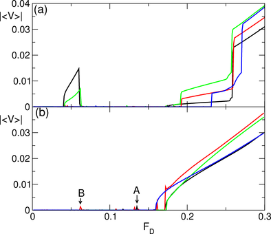
 Figure 8:
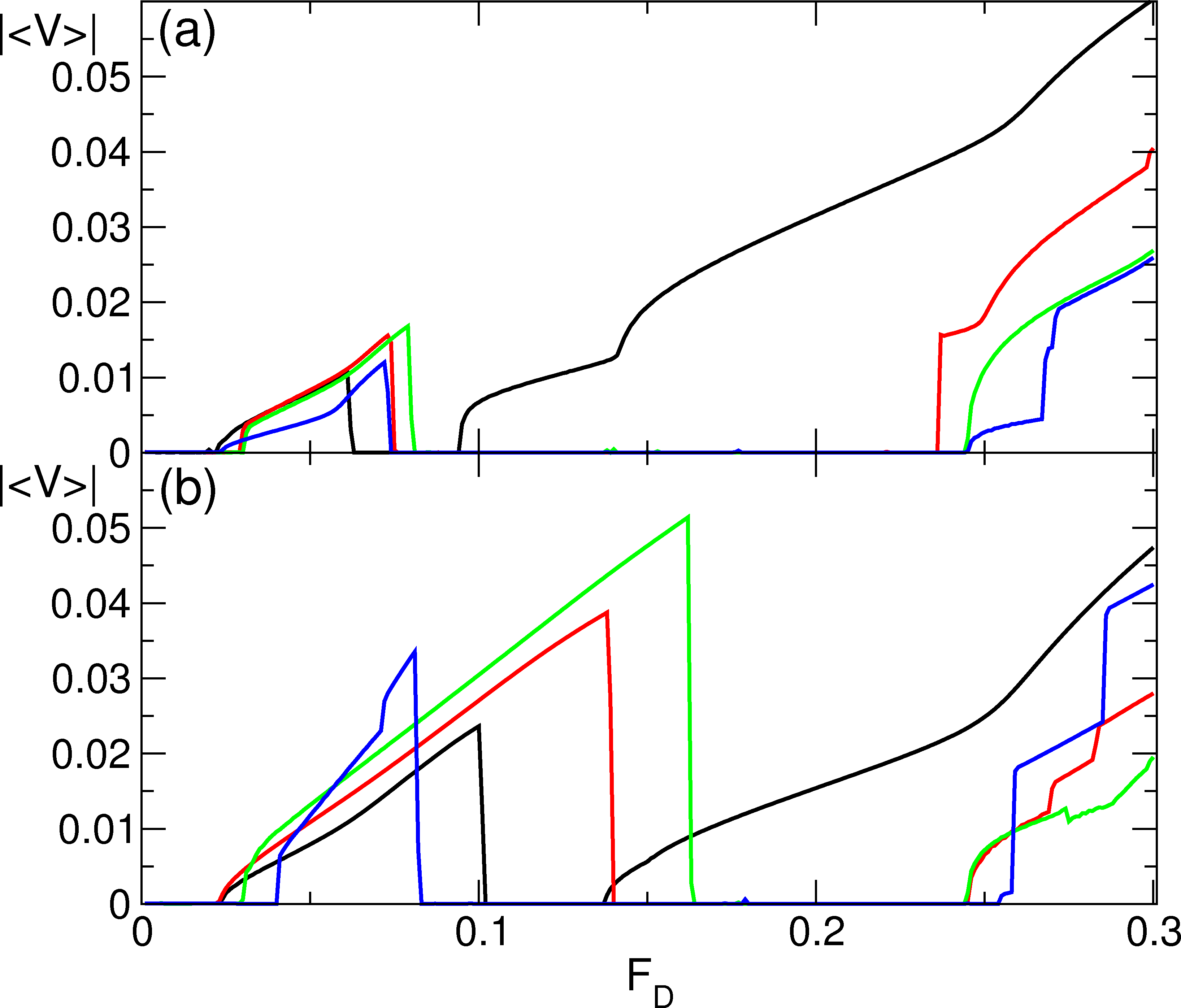
|〈V〉| vs FD for driving in the hard direction at
Nc = 8.25 (black), 8.5 (red), 8.75 (green), and 10.5 (blue).
There is a single depinning transition for Nc = 8.5 and Nc=10.5,
and at these fillings
there is a direct transition from a pinned to
a clogged state without an intermediate flowing
state.
(b) |〈V〉| vs FD for Nc = 9.25 (black), 10.75 (red),
11.0 (green), and 12.0 (blue).
The point marked A indicates the value of FD
at which there is a transition from the pinned to the clogged state
for the Nc = 9.25 system, and
the point marked B indicates the same transition for the
Nc = 10.75 system.
Figure 8:
|〈V〉| vs FD for driving in the hard direction at
Nc = 8.25 (black), 8.5 (red), 8.75 (green), and 10.5 (blue).
There is a single depinning transition for Nc = 8.5 and Nc=10.5,
and at these fillings
there is a direct transition from a pinned to
a clogged state without an intermediate flowing
state.
(b) |〈V〉| vs FD for Nc = 9.25 (black), 10.75 (red),
11.0 (green), and 12.0 (blue).
The point marked A indicates the value of FD
at which there is a transition from the pinned to the clogged state
for the Nc = 9.25 system, and
the point marked B indicates the same transition for the
Nc = 10.75 system.
|