Physical Reivew B 61, 3665 (2000)

Dynamic Vortex Phases and Pinning in Superconductors with Twin Boundaries

C. Reichhardt1,2 C.J. Olson1,2, and Franco Nori1

1.  Department of Physics, The University of Michigan, Ann Arbor, Michigan 48109-1120
2.  Department of Physics, University of California, Davis, CA 95616

(Received 23 August 1999)

We investigate the pinning and driven dynamics of vortices interacting with twin boundaries using large scale molecular dynamics simulations on samples with near one million pinning sites. For low applied driving forces, the vortex lattice orients itself parallel to the twin boundary and we observe the creation of a flux gradient and vortex free region near the edges of the twin boundary. For increasing drive, we find evidence for several distinct dynamical flow phases which we characterize by the density of defects in the vortex lattice, the microscopic vortex flow patterns, and orientation of the vortex lattice. We show that these different dynamical phases can be directly related to microscopically measurable voltage-current V(I) curves and voltage noise. By conducting a series of simulations for various twin boundary parameters we derive several vortex dynamic phase diagrams.
I. INTRODUCTION
II. SIMULATION
III. DYNAMIC PHASES
IV. CURRENT-VOLTAGE CHARACTERISTICS AND VORTEX STRUCTURE
V. NOISE MEASUREMENTS
VI. DYNAMIC PHASE DIAGRAMS
VII. CONCLUSION
References

I.  INTRODUCTION

The understanding of vortex pinning and dynamics in high-Tc superconductors is of great interest for applications of superconductors which require strong pinning of vortices as well as the rich variety of behaviors that arise due to the competition of a static or driven elastic media with various forms of quenched disorder [1]. The physics of a vortex lattice interacting with disorder is relevant for a wide variety of condensed matter systems including charge-density-waves, driven Wigner crystals, magnetic bubble arrays, colloids, Josephson junction arrays and superconducting wire networks, as well as microscopic models of friction.
Twin boundaries are a very common defect found in YBa2Cu3O7−x(YBCO) and their pinning properties have been extensively studied using Bitter decoration [2], torque magnetometry [3], magnetization [4,5,6,7] transport [8], magneto-optical imaging [9,10,11,12,13,14], and theoretical studies [15,16,17]. Many of the earlier experiments on twinned YBCO samples found conflicting evidence for the role of twin boundaries in vortex pinning. In particular, the magneto-optical measurements by Duran et al. [9] had shown that twin boundaries act as areas of reduced pinning that allow easy flux penetration, whereas studies by Vlasko-Vlasov et al. [10] found the twin boundaries to be barriers to flux motion. Further magneto-optical studies [11,12,13,14], systematic computer simulations [17], and transport measurements [8] have shown that these conflicting results can be resolved when the direction of the Lorentz force with respect to the twin boundary is considered. The twin boundary (TB) acts as an easy-flow channel when the Lorentz force is parallel to the twin, but acts as a strong barrier for forces perpendicular to the TB.
A very systematic simulational study, using samples with of the order of a million pinning sites, by Groth et al. [17] of the angular dependence of the Lorentz force with respect to the twin boundary showed that, when the angle between the Lorentz force and the twin is large, a portion of the vortices get trapped inside the twin. This produces a pile-up effect leading to a higher density of vortices on one side of the twin in agreement with observations by several groups including, for example, Vlasko-Vlasov et al. [10], Welp et al. [12], and Wijngaarden et al. [14]. At lower angles between the Lorentz force and the twin, simulations [17] show that the flux moves in channels along the twin boundary while some guided motion of vortices along the edge of the twin still occurs. At the lowest angles the flux flows most easily along the twin with a number of vortices escaping from the twin and forming a flame pattern flux profile in agreement with magneto-optical experiments [9,10,18,14].
Recently interest in vortex systems has strongly focused on driven phases and dynamic phase transitions of vortices interacting with random or periodic defects in superconductors. The anisotropic pinning properties of twin boundaries as well as the possibility of tuning the strength of the twin boundary pinning make these defects quite distinct from random pinning or periodic pinning arrays, so that new dynamical phases can be expected to appear.
In systems containing random pinning, experiments using transport measurements [19,20,21], voltage noise measurements [22,23], vibrating reed measurements [24], neutron scattering [25], and Bitter-decoration [26], as well as simulational work [27,28], and work based on perturbation and/or elasticity theory [29] indicate that, at the depinning transition, the vortex lattice may disorder and undergo plastic flow in which vortices change nearest neighbors as mobile portions of the vortex lattice tear past pinned portions. At higher drives the vortex lattice may reorder and exhibit elastic or ordered flow. An intriguing question is whether specific types of plastic flow exist, and how they could be distinguished. Simulations with randomly placed pinning indicate the possible existence of at least two kinds of plastic flow. The first type consists of well-defined channels of mobile vortices flowing through the rest of the pinned vortex lattice [30,31,32,33]. A second type consists of intermittent or avalanching motion in which only a few vortices are mobile at any given time, but over time all the vortices take part in the motion so that well defined channels are not observed [31,32,33].
Recent simulations using the time-dependent Ginzburg-Landau equations at T = 0 of vortices interacting with twin boundaries have suggested the possibility of the existence of three distinct flow phases which include two plastic flow phases and an elastic flow phase [18]. Due to the nature of these simulations it was only possible to consider three different driving currents for each pinning parameter; so that V(I) curves, voltage noise signals, and the evolution of the vortex order as a continuous function of increasing driving force could not be extracted, nor could the evolution of the flow phases with the system parameters be determined.
In order to examine the microscopic dynamics of vortices interacting with twin boundaries we have performed large scale molecular dynamics simulations for a wide variety of twin parameters which allow us to carefully compare the different kinds of plastic flow as a driving force is continuously increased. Our results in this work complement our previous simulational work on twin-boundaries [17], where we considered only the case of very slow driving that occurs as a magnetic field is increased. In Ref. [17] we considered flux-gradient-driven vortices and we focused on the magnetic flux front profiles and compared them to magneto-optical images. In this paper we focus on the microscopic aspects of current-driven, as opposed to flux-gradient-driven, vortex motion and structure as well as on transport measures.

II.  SIMULATION

We consider an infinite 2D slice in the x-y plane of an infinitely long (in the z direction) parallelepiped. We use periodic boundary conditions in the x-y plane and simulate stiff vortices that are perpendicular to the sample (i.e, H = Hz). These rigid flux lines can also be thought of as representing the "center of mass" positions of real, somewhat flexible vortices, and the pinning in the bulk as representing the average of the pinning along the length of the real vortex. For flexible vortices, the bulk pinning can be on the same order as the twin-boundary pinning even for large samples. We numerically integrate the overdamped equations of motion:
fi = fivv + fivp + fivTB +fd =  ηvi .
(1)
Here, fi is the total force on vortex i , fivv is the force on the ith vortex from the other vortices, fivp is the force from the vortex pin interaction, fivTB is the force from the vortex-twin interaction, and fd is the driving force; vi is the net velocity of vortex i and η is the viscosity, which is set equal to unity in this work. The interaction between vortex i and other vortices is given by:
 fivv =   Nv

j=1 
 f0  K1
|rirj|

λ

 
^
r
 

ij 
 .
(2)
Here, ri is the location of vortex i and rj is the location of vortex j, f0 = Φ02/8π2λ3 , Φ0 = hc/2e is the elementary flux quantum, λ is the penetration depth, Nv is the number of vortices, and rij = (rirj)/|rirj|. The force between vortices decreases exponentially at distances greater than λ, and we cut off this force for distances greater than 6λ. A cutoff is also placed on the force for distances less than 0.1λ to avoid the logarithmic divergence of forces. These cutoffs have been found to produce negligible effects for the range of parameters we investigate here. For convenience, throughout this work all lengths are measured in units of λ, forces in units of f0, and fields in units of Φ02.
To model pinning in the bulk, we divide our system into a 1000×1000 grid where each grid element represents a pinning site. The pinning density np is 496/λ2, which is within experimentally determined values. At each pinning site (l,m) the pinning force fl,mthr is chosen from a uniform distribution [0,fp], where fp is the maximum possible pinning force. If the magnitude of the force produced by the other vortices, driving force and twin boundaries acting on a vortex located on a pinning site (l,m) is less than the threshold pinning force fl,mthr, the vortex remains pinned at the pinning site. If the force on the vortex is greater than fl,mthr, then the effective pinning force fivp drops to zero and the vortex moves continuously until it encounters a pinning site that has a threshold force greater than the net force on the vortex. The pinning therefore acts as a stick-slip friction force with the following properties
fivp   =  − finet,       finet < fl,mthr
(3)
and
fivp   =  0,       finet > fl,mthr   .
(4)
For the twin boundary pinning, we have considered a large number of models, all giving similar results. The simplest model that is most consistent with experiments is that of an attractive well containing stick-slip pinning with a different maximum threshold force fpTB than that of the bulk pinning outside the TB, fp. This model of pinning is very similar to the one inferred from the measurements in [5] where the TB channel has strong depth variations. The ratio fpTB/fp is expected to vary as a function of temperature. In the case predicted for low T [1] where fpTB/fp < 1, the twin boundary acts as an easy flow channel for certain angles [17]. On the other hand, at higher T, fpTB/fp > 1, and the twin acts as a barrier to flux flow. This second case is the most similar to the simulations conducted in [18] where the twin boundary was modeled as a line of parabolic pinning. In our simulations we can mimic the effects of temperature by varying the ratio of fpTB/fp.
The twin boundary itself is modeled as an attractive parabolic channel with a width denoted by 2ξTB. The force on the ith vortex due to the kth the twin boundary is
fivTB    =   fTB
dikTB

ξTB

 Θ
ξTBdikTB

λ

 
^
r
 

ik 
(5)
where dikTB is the perpendicular distance between the ith vortex and the kth twin boundary.
The driving force representing the Lorentz force from an applied current is modeled as a uniform force on all the vortices. The driving force is applied in the x-direction and is slowly increased linearly with time. We examine the average force in the x-direction
Vx = 1

Nv
Nv

i=1 
  vi·
^
x
 
 ,
(6)
as well as the average force in the y-direction
Vy = 1

Nv
Nv

i=1 
  vi·
^
y
 
 .
(7)
These quantities are related to macroscopically measured voltage-current V(I) curves.
We also measure the density of 6-fold coordinated vortices P6. Strong plastic flow causes an increase in the number of defects and a corresponding drop in P6, while elastic flow is associated with few or no defects. Another measure of order in the lattice is the average height of the first-oder peaks in the structure factor S(k).
S(k) = 1

L2


i,j 
eik·(rirj)  .
(8)
The defect density can also be correlated with the voltage noise power spectra S(ν).
S(ν) =
Vx(t)  eiνt  dt  .
(9)
A vortex lattice that is flowing plastically should produce a large amount of voltage noise. To measure the quantity of noise produced, we integrated the noise power over one frequency octave [22,23].

III.  DYNAMIC PHASES

Fig1.png
Figure 1: 
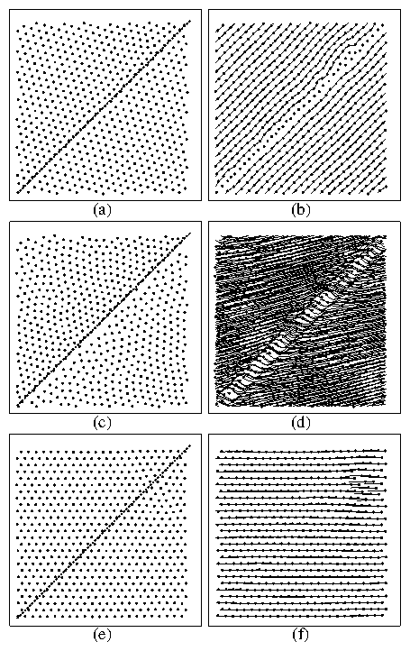
The vortex positions (left column) and flow patterns (right column) for three different applied drives. Panels (a,b), with fd/f0 = 0.05, show guided plastic motion. Panels (c,d), with fd/f0 = 0.35 show a slightly more disordered motion, exhibiting some plasticity, tearing, and healing. Specifically, the vortex lattice is slightly torn apart by the twin boundary, but it heals right after crossing it. Panels (e,f), with fd/f0 = 1.25, show elastic flow.
In order to directly observe the nature of the vortex flow in the presence of twin boundaries, we have imaged the trajectories of the moving vortices as the driving current along the x-axis is increased. We find three types of vortex flow, which are shown in Fig. 1. There, and for three different applied driving forces, we show the vortex positions (dots) and the trajectories (lines) that the vortices follow when interacting with a twin boundary (dotted line) that acts as a strong pinning barrier for motion across the twin. Here fp = 0.02f0, fTBp = 1.0f0, fTB = 0.15f0, with the twin boundary having a width of 0.5λ. In Fig. 1(a) for the lowest drive, fd = 0.05f0, the vortex lattice is predominantly triangular, and aligned with the twin plane. The vortices that have struck the twin boundary are pinned, while the remaining vortices flow in an orderly fashion at a 45 degree angle from the x axis, as seen in Fig. 1(b). The moving vortices do not cross the twin boundary but are instead guided so that the vortices do not move parallel to the direction of the applied driving force. We term this phase guided plastic motion (GPM), since vortex neighbors slip past each other near the twin boundary. The vortices trapped in the twin boundary remain permanently pinned in this phase. We also observe a build-up or a higher density of flux lines along one side of the twin boundary. This type of density profile has been previously observed in flux-gradient driven simulations and magneto-optical experiments.
At higher drives, as shown in Fig. 1(c,d) with fd = 0.35f0, there is a transition to a more disordered flow and the vortices start to cross the twin boundary. The overall vortex structure [Fig. 1(c)] is more disordered than it was at lower drives [Fig. 1(a)]. Unlike the guided plastic motion phase, the vortices pinned along the twin boundary are only temporarily trapped, and occasionally escape from the twin and are replaced by new vortices intermittently. The vortex trajectories shown in Fig. 1(d) also indicate that some vortex guiding still occurs. We label this phase the plastic motion (PM) phase. At even higher driving currents we observe a transition from the plastic flow phase to an elastic motion (EM) phase where the effect of the twin boundary becomes minimal, as shown in Fig. 1(e,f) for fd = 1.25f0. Here, the vortex lattice reorders [Fig. 1(e)], the vortices flow along the direction of the applied Lorentz force [Fig. 1(f)], and no build-up of the flux near the twin appears.

IV.  CURRENT-VOLTAGE CHARACTERISTICS AND VORTEX STRUCTURE

Fig2.png
Figure 2: (a) The longitudinal Vx and transverse Vy average velocity versus driving force for a system in which the twin boundary is represented by a rough channel with strong pinning. Here the twin has a maximum pinning of 1.0 f0 and the point pinning has a maximum of 0.02 f0. The inset of (a) shows how Vx linearly increases with fd for the same system in (a). (b) The average six-fold coordination number P6. (c) The average magnitude < S(k) > of the first order peaks of the structure factor. In the disordered plastic motion regime the low values of both P6 and < S(k) > reflect the large degree of disorder. The transition to the elastic flow regime is marked by the large increase in order indicated by P6 and < S(k) > , as well as by the loss of guided motion which occurs when Vy ≈ 0.
In order to quantify the phases illustrated in Fig. 1, we analyze the transverse Vy and longitudinal Vx average vortex velocities, as well as the six-fold coordination number P6 and the average value of the first order peaks in the structure factor, < S(k) > , as a function of applied drive. As shown in Fig. 2, for drives less then the bulk pinning, fd < fp = 0.02f0, the vortex lattice is pinned and Vy = Vx = 0. For low drives, 0.02f0 < fd < 0.17f0, the vortex velocities increase linearly with driving force, and VxVy indicating that the vortices are following the twin boundary by moving at a 45° angle, as was shown in Fig. 1(b). The fraction of six-fold coordinated vortices, P6 = 0.8, remains roughly constant throughout the guided plastic motion phase. Above fd/f0 = 0.225, two trends are observed. First, the longitudinal velocity Vx continues to increase. This trend can be better seen in the inset of Fig. 2(a), which has a larger range of values for the vertical axis in order to monitor the linear growth over a wider range of velocities. Second, the transverse velocity Vy flattens and then begins to decrease, indicating that the vortices have begun to move across the twin boundary.
The vortex lattice becomes slightly more disordered in this plastic flow phase as indicated by the drop in P6 and the smaller drop in < S(k) > . As fd is increased further, Vy gradually decreases, but remains finite as vortices cross the twin at an increasing rate. When Vy approaches zero, near fd/f0 = 0.85, the vortex lattice reorders as indicated by the increase in P6 and < S(k) > . We note that the reordering transition in P6 is considerably sharper than that typically observed in simulations with random pinning.

V.  NOISE MEASUREMENTS

Fig3.png
Figure 3: The average noise power S0 versus driving force fd for the same system in Fig. 2. In the guided plastic (low fd) and elastic (high fd) flow regimes the noise power is low. However, in the intermediate-drive disordered plastic flow regime the noise power is high, and gradually decreases as fd is increased.
An indirect experimental probe of the plastic vortex motion is the voltage noise produced by the flowing flux. During plastic flow the voltage noise is expected to be maximal. Indeed, in simulations with random pinning [28,33], large noise power was associated with the highly plastic motion of a disordered vortex lattice. Further, large noise is considered a signature for plastic flow in the peak effect regime. In order to compare the different plastic flow phases seen here with those observed for random pinning, we measure the noise power for each phase and plot the results in Fig. 3 along with the corresponding Vy versus fd curve.
The noise power is relatively low in the GPM phase, increases to a large value in the PM phase, and then gradually decreases as the EM phase is approached. In the GPM regime, although tearing of the vortex lattice occurs at the boundaries between the pinned and flowing vortices, the vortex trajectories follow fixed channels and a large portion of the vortex lattice remains ordered. This very orderly vortex motion produces little noise. In the PM phase, the vortex lattice is highly disordered and the trajectories follow continuously changing paths so the corresponding voltage noise power is high. This difference in noise power between the static and changing channels for vortex flow agrees well with results obtained in systems with strong random pinning. In such systems, when the vortex flow follows fixed winding channels that do not change with time, low noise power is observed above the depinning threshold [28,33]. Similarly, when the pinning is weak and the vortices move in straight fixed lines, low voltage noise is observed [28,33]. This latter case agrees well with the result seen here in the GPM and EM phases, when the vortices follow straight paths and produce little noise power.

VI.  DYNAMIC PHASE DIAGRAMS

Fig4.png
Figure 4: (a) Transverse and longitudinal velocities versus driving force for varying twin-boundary strengths: from top to bottom fp/f0 = 0.25, 0.5, 0.75, 1, 1.25. The top curve corresponds to the case fp/f0 = 1.25. The second curve, from the top, corresponds to the same sample used in Figs. 1 and 2. (b) The fraction of six-fold coordinated vortices P6 versus driving. For increasing pinning strength the width of both the guided and plastic flow phases increases.
Fig5.png
Figure 5: (a) The dynamic phase diagram for the system in Fig. 4. For increasing fp the PM-EM transition line increases as ∝ fp while the GPM to PM transition increases much more slowly. (b) The dynamic phase diagram for constant fpTB but decreasing vortex density. The PM-EM transition line remains roughly constant while the GPM-PM transition line shifts to higher fd as the effective vortex-vortex interaction decreases.
To generalize our results to other parameters, we construct a phase diagram of the dynamic phases. We first measure the evolution of Vx, Vy and P6 as a function of driving force for varying fpTB from 1.25f0 to 0.25f0. These are seen in Fig. 4. When the pinning strength fpTB inside the twin increases, the width of the PM region grows, and the amount of disorder in the vortex lattice increases, as seen in the decrease of P6. From the curves shown in Fig. 4, we construct a dynamic phase diagram which is plotted in Fig 5(a). We determine the transition between the guided plastic and plastic flow phase from the onset of disorder in P6 and the downturn in Vy, whereas the plastic motion to elastic motion transition line is marked at the point when P6 begins to plateau. The driving force fd at which both the GPM-PM and PM-EM transitions occur each grow linearly with fp. In particular, the PM-EM transition roughly follows fd = fpTB, indicating that the vortex lattice reorders once the pinning forces are overcome.
It might be expected that the transition out of the guided plastic motion phase would fall at fd = fpTB, when the vortices are able to depin from the twin boundary. Since vortex interactions are important, however, in actuality the vortex density increases on one side of the twin while a lower vortex density appears on the other side. This localized flux gradient produces an additional force on the vortices at the twin boundary, depinning them at a driving force fd < fpTB. The additional force from the flux-gradient is not spatially uniform, unlike the driving force, so some of the vortices will depin before others in a random manner. Once the applied driving force and the gradient force are large enough to start depinning vortices from the twin, the flux lines enter the plastic flow phase. The effect of the pinning on the vortices does not fully disappear until fd > fpTB, however, which is seen in the existence of a finite Vy. We also note that there is a pinned phase where no vortex motion occurs when fd < fp.
By changing the vortex density we can examine the effects of changing the effective vortex-vortex interaction. In Fig. 5(b) we plot the phase diagram constructed from a series of simulations in which the vortex density is varied. As the vortex density decreases the GPM-PM and the PM-EM transition lines shift to higher drives. This is because lower values of B (or Nv) increase the effective pinning force and shift the boundary to higher values of fd.

VII.  CONCLUSION

We have examined the dynamics of driven superconducting vortices interacting with twin boundary pinning. We find three distinct flow phases as a function of driving force. In the guided plastic motion phase, the partially ordered vortex lattice flows in stationary channels aligned with the twin boundary. In this phase the transverse and longitudinal velocities are equal and there is only a small amount of noise in the velocity signals. At higher drives, a flux gradient builds up along the twin and the vortices begin to cross the twin boundary intermittently. In this phase the vortex lattice is disordered and a large amount of voltage noise appears. The guiding effect of the twin gradually decreases for increasing drives and the vortex lattice reorders, producing an elastic flow phase. By conducting a series of simulations we have constructed phase diagrams both as a function of twin boundary pinning strength and as a function of the vortex density. The phase boundaries all shift linearly in driving force as the pinning strength increases. As the vortex density is lowered the width of the guided motion region increases, while the onset of the elastic motion phase is constant.
Twin boundaries correspond to one type of correlated pinning. Another type involves periodic arrays of pinning sites [34]. The dynamic phase diagrams of these structures with correlated pinning are also under current intense investigation.
Note Added: After completing this work we became aware of the experiments in Ref. [35] which measure both the longitudinal and transverse voltage signal for vortices driven in samples with unidirectional twin-boundaries. When the vortices are driven at 52 degrees with respect to the twin boundaries, at low temperatures the vortex motion deviates strongly from the direction of drive with a component moving along the twin boundary. Using this experimental set-up it should be possible to observe both the transverse and longitudinal vortex velocity as a function of applied current.

References

[1]
G. Blatter, M.V. Feigel'man, V.B. Geshkenbein, A.I. Larkin, and V.M. Vinokur, Rev. Mod. Phys. 66, 1125 (1994).
[2]
L.Ya. Vinnikov, L.A. Gurevich, G.A. Yemelchenko, and Yu.A. Ossipyan, Solid State Commun. 67, 421 (1988); G.J. Dolan, G.V. Chandrashekhar, T.R. Dinger, C. Feild, and F. Holtzberg, Phys. Rev. Lett. 62, 827 (1989).
[3]
E.M. Gyorgy, R.B. van Dover, L.F. Schneemeyer, A.E. White, H.M. O'Bryan, R.J. Felder, J.V. Waszczak, W.W. Rhodes, and F. Hellman, Appl. Phys. Lett. 56, 2465 (1990).
[4]
L.J. Swartzendruber, D.L. Kaiser, F.W. Gayle, L.H. Bennett, and A. Roytburd, Appl. Phys. Lett. 58, 1566 (1991); D.L. Kaiser, F.W. Gayle, L.J. Swartzendruber, L.H. Bennett, and R.D. McMichael, J. Appl. Phys. 70, 5739 (1991).
[5]
M. Oussena, P.A.J. de Groot, S.J. Porter, R. Gagnon, and L. Taillefer, Phys. Rev. B 51, 1389 (1995).
[6]
B.M.  Lairson, S.K. Streiffer, and J.C. Bravman, Phys. Rev. B 42, 10067 (1990).
[7]
A.A. Zhukov, H. Kupfer, G. Perkins, L.F. Cohen, A.D. Caplin, S.A. Klestov, H. Claus, V.I. Voronkova, T. Wolf, and H. Wuhl, Phys. Rev. B 51, 12704 (1995); A.A. Zhukov, H. Kupfer, H. Claus, H. Wuhl, M. Klaser, and G. Muller-Vogt, Phys. Rev. B 52, R9871 (1995).
[8]
H. Safar, S. Foltyn, H. Kung, M.P. Maley, J.O. Willis, P. Arendt, and X.D. Wu, Appl. Phys. Lett. 68, 1853 (1996).
[9]
C.A. Durán, P.L. Gammel, R. Wolfe, V.J. Fratello, D.J. Bishop, J.P. Rice, and D.M. Ginsberg, Nature 357, 474 (1992).
[10]
V.K. Vlasko-Vlasov, L.A. Dorosinskii, A.A. Polyanskii, V.I. Nikitenko, U. Welp, B.W. Veal, and G.W. Crabtree, Phys. Rev. Lett. 72, 3246 (1994).
[11]
C.A. Durán, P.L. Gammel, D.J. Bishop, J.P. Rice, D.M. Ginsberg, U. Welp, T. Gardiner, D.O. Gunter, B.W. Veal, G.W. Crabtree, V.K. Vlasko-Vlasov, and V.I. Nikitenko, Phys. Rev. Lett. 74, 3712 (1995).
[12]
U. Welp, T. Gardiner, D.O. Gunter, B.W. Veal, G.W. Crabtree, V.K. Vlasko-Vlasov, and V.I. Nikitenko, Phys. Rev. Lett. 74, 3713 (1995).
[13]
U.  Welp, T. Gardiner, D. Gunter, J. Fendrich, G.W. Crabtree, V.K. Vlasko-Vlasov, and I. Nikitenko, Physica 235C, 241 (1994).
[14]
R.J. Wijngaarden, R. Griessen, J. Fendrich and W.-K. Kwok, Phys. Rev. B 55, 3268 (1997).
[15]
I.N. Khlyustikov and A.I. Buzdin, Adv. Phys. 36, 271 (1987).
[16]
D.R. Nelson and V.M. Vinokur, Phys. Rev. B 48, 13060 (1993); M.C. Marchetti and V.M. Vinokur, Phys. Rev. Lett. 72, 3409 (1994).
[17]
J. Groth, C. Reichhardt, C.J. Olson, S. Field, and F. Nori, Phys. Rev. Lett. 77, 3625 (1996).
[18]
G.W. Crabtree, G.K. Leaf, H.G. Kaper, V.M. Vinokur, A.E. Koshelev, D.W. Braun, D.M. Levine, W.K. Kwok, and J.A. Fendrich, Physica C 263, 401 (1996).
[19]
G. D'Anna, M.V. Indenbom, M.-O. Andre, W. Benoit, and E. Walker, Europhys. Lett. 25, 225 (1994).
[20]
M.C. Hellerqvist, D. Ephron, W.R. White, M.R. Beasley and A. Kapitulnik, Phys. Rev. Lett. 76, 4022 (1996).
[21]
W. Henderson, E.Y. Andrei, M.J. Higgins, and S. Bhattacharya, Phys. Rev. Lett. 77, 2077 (1996).
[22]
R.D. Merithew, M.W. Rabin, M.B. Weissman, M.J. Higgins, and S. Bhattacharya, Phys. Rev. Lett. 77, 3197 (1996); M.W. Rabin, R.D. Merithew, M.B. Weissman, M.J. Higgins, and S. Bhattacharya, Phys. Rev. B 57, R720 (1998);
[23]
G. D'Anna, P.L. Gammel, H. Safar, G.B. Alers, D.J. Bishop, J. Giapintzakis, and D.M. Ginsberg, Phys. Rev. Lett. 75, 3521 (1995).
[24]
J. Zhang, L.E. DeLong, V. Majidi, R.C. Budhani, Phys. Rev. B 53, R8851 (1996).
[25]
U. Yaron, P.L. Gammel, D.A. Huse, R.N. Kleiman, C.S. Oglesby, E. Bucher, B. Batlogg, D.J. Bishop, K. Mortensen, K. Clausen, C.A. Bolle, and F. de la Cruz, Nature 376, 753 (1995).
[26]
A. Duarte, E. Fernandez Righi, C.A. Bolle, F. de la Cruz, P.L. Gammel, C.S. Oglesby, B. Bucher, B. Batlogg, and D.J. Bishop, Phys. Rev. B 53, 11336 (1996); M. Marchevsky, J. Aarts, P.H. Kes, and M.V. Indenbom, Phys. Rev. Lett. 78, 531 (1997); F. Pardo, F. de la Cruz, P.L. Gammel, E. Bucher, and D.J. Bishop, Nature 396, 348 (1998).
[27]
A.E. Koshelev and V.M. Vinokur, Phys. Rev. Lett. 73, 3580 (1994); M.C. Faleski, M.C. Marchetti, and A.A. Middleton, Phys. Rev. B 54, 12427 (1996); K. Moon, R.T. Scalettar, and G.T. Zimányi, Phys. Rev. Lett. 77, 2778 (1996); S. Ryu, M. Hellerqvist, S. Doniach, A. Kapitulnik, and D. Stroud, Phys. Rev. Lett. 77, 5114 (1996); S. Spencer and H.J. Jensen, Phys. Rev. B 55, 8473 (1997).
[28]
C.J. Olson, C. Reichhardt, and F. Nori, Phys. Rev. Lett. 81, 3757 (1998).
[29]
S. Scheidl and V.M. Vinokur, Phys. Rev. E 57, 2574 (1998); T. Giamarchi and P. Le Doussal, Phys. Rev. B 57, 11356 (1998); L. Balents, M.C. Marchetti, and L. Radzihovsky, Phys. Rev. B 57, 7705 (1998).
[30]
H.J. Jensen, A. Brass and A.J. Berlinsky, Phys. Rev. Lett. 60, 1676 (1988).
[31]
N. Gronbech-Jensen, A.R. Bishop, and D. Dominguez, Phys. Rev. Lett. 76, 2985 (1996).
[32]
C.J. Olson, C. Reichhardt, and F. Nori, Phys. Rev. B 56, 6175 (1997).
[33]
C.J. Olson, C. Reichhardt, and F. Nori, Phys. Rev. Lett. 80, 2197 (1998).
[34]
C. Reichhardt, C.J. Olson, and F. Nori, Phys. Rev. B 58, 6534 (1998); 57, 7937 (1998); Phys. Rev.Lett. 78, 2648 (1997); C. Reichhardt and F. Nori, ibid. 82, 414 (1999); C. Reichhardt, C.J. Olson, J. Groth, S. Field, and F. Nori, Phys. Rev. B 54, 16108 (1996); 56 14196 (1997).
[35]
H. Pastoriza, S. Candia and G. Nieva, to be published.


File translated from TEX by TTHgold, version 4.00.

Back to Home