Active Microrheology, Hall Effect, and Jamming in Chiral Fluids
C. Reichhardt and C.J.O. Reichhardt
Theoretical Division and Center for Nonlinear Studies, Los Alamos National Laboratory,
Los Alamos, New Mexico 87545, USA
(Dated: July 25, 2022)
We examine the motion of a probe particle driven through a chiral fluid composed of circularly
swimming disks. We find that the probe particle travels in both the longitudinal direction, parallel
to the driving force, and in the transverse direction, perpendicular to the driving force, giving rise
to a Hall angle. Under constant driving force, we show that the probe particle velocity in both the
longitudinal and transverse directions exhibits nonmonotonic behavior as a function of the activity
of the circle swimmers. The Hall angle is maximized when a resonance occurs between the frequency
of the chiral disks and the motion of the probe particle. As the density of the chiral fluid increases,
the Hall angle gradually decreases before reaching zero when the system enters a jammed state. We
show that the onset of jamming depends on the chiral particle swimming frequency, with a fluid
state appearing at low frequencies and a jammed solid occurring at high frequencies.
I. INTRODUCTION
II. SIMULATION AND SYSTEM
III. RESULTS
IV. SUMMARY
REFERENCES
I. Introduction
A variety of systems can be described as assemblies of particles that exhibit chiral or circular motion [1, 2], such as circularly
moving colloids [3–6], biological circle swimmers [7], active spinners [8–12], circularly driven particles [13–17], and chiral robot
swarms [18]. Other systems in which chiral or gyroscopic motion occurs include skyrmions in chiral magnets [19, 20] and
classical charged particles moving in a magnetic field [21]. Such chiral particle assemblies can exhibit a variety of dynamical
phases such as large scale rotations [18], self-assembly [5, 6, 8, 9, 11], edge currents [5, 9, 15, 22], and odd viscosity
responses [10, 23, 24].
Damping, fluctuations, and jamming in particle assemblies can be examined at the local level using active rheology, which is
based on the response of a probe particle that is driven at either constant force or constant velocity through a
fluid or jammed medium [25–30]. Active rheology has been applied to the onset of jamming [26, 27, 31–34],
where the threshold for probe particle motion increases from zero to a finite value at the jamming transition. It
has been used to measure changes in viscosity and diffusive responses [26, 35–40] as well as velocity-force
relations [25, 26, 32, 41–44]. Active rheology has been applied not only to soft matter systems, but also to
the dynamics of individual vortices dragged across pinning landscapes in type-II superconductors [45–47]. In
systems that are active rather than passive, active rheology shows large changes in the velocity of the probe
particle as a function of increasing bath activity when the system transitions from a fluid state to an actively
phase separated state [48]. In each case, when the probe particle is driven at constant force, it moves in the
direction of drive and exhibits symmetric fluctuations in the transverse direction, with no transverse drift or Hall
velocity.
Here we study the active rheology of a probe particle driven through a chiral fluid of circularly swimming disks. We find
that for low and intermediate fluid densities, the probe particle exhibits a longitudinal velocity ⟨V long⟩ in the direction of
drive as well as a finite transverse or Hall velocity ⟨V trans⟩, giving rise to a Hall effect with a Hall angle of
θHall = arctan(⟨V trans⟩∕⟨V long⟩). We examine the evolution of the Hall angle as a function of applied driving force,
temperature, and chiral fluid density, and find Hall angles that are as large as θHall = 45∘. We also observe non-monotonic
behavior of θHall in which the transverse velocity is maximized when a commensuration occurs between the chiral disk
rotation frequency and the time interval between consecutive collisions of the probe particle with the chiral disks. In general,
θHall decreases with increasing chiral disk density, and it drops to zero at high densities when a jammed state appears. In the
dense limit, the probe particle can move only when the driving force is larger than a finite threshold value, and this
threshold depends strongly on the chiral disk swimming frequency. At low frequencies, the threshold is nearly
zero, while at high frequencies, the threshold increases when the system acts like a solid. We compare the
dynamics of the probe particle to driven skyrmions which have recently been shown to exhibit a skyrmion Hall
effect that also exhibits nonmonotonic behavior as a function of dc drive, temperature, and skyrmion density
[49–53].
II. Simulation and System
We consider a two-dimensional L×L system with L = 36 in which we place N non-overlapping disks with a radius Rd = 0.5,
where the disks have repulsive harmonic interactions. The density of the system is characterized by the area covered by the
disks, ϕ = NπRd2∕L2. For monodisperse disks at T = 0, when ϕ = 0.9 the system forms a triangular solid in which the disks
are just touching. The force between disks i and j is given by Fppij = k(rij - 2Rd)Θ(rij - 2Rd) ij, where rij = |ri - rj|,
 ij = (ri - rj)∕rij, and Θ is the Heaviside step function. The spring stiffness is set to k = 50, ensuring that the maximum
overlap between disks is less than one percent. The densities and parameters we consider here have also been studied in
previous works [15, 32, 48]. The dynamics of disk i is determined by the following overdamped equation of
motion:
ij = (ri - rj)∕rij, and Θ is the Heaviside step function. The spring stiffness is set to k = 50, ensuring that the maximum
overlap between disks is less than one percent. The densities and parameters we consider here have also been studied in
previous works [15, 32, 48]. The dynamics of disk i is determined by the following overdamped equation of
motion:
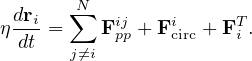 | (1) |
We set the damping constant η = 1 and our simulation time step is Δt = 0.002. Here Fcirci is a driving force that creates a
circular motion of the disks of the form Fcirci = A(sin(ωt) + cos(ωt)ŷ), controlled by varying the drive amplitude A. All of
the chiral disks move in phase with each other. The thermal force FT is produced by Langevin kicks with the
properties ⟨FiT(t)⟩ = 0 and ⟨FiT(t)FjT(t′)⟩ = 2ηkBTδijδ(t - t′). Unless otherwise noted, we fix FT = 2.0, a
value large enough to maintain the system in a liquid state up to the solidification density ϕ = 0.9. We note
that the thermal kicks cause each particle to undergo diffusive behavior at long time scales, which could be
appropriate for many types of active colloidal systems. To create our probe particle, we select a single disk
and replace Fcirci with FD = FD
+ cos(ωt)ŷ), controlled by varying the drive amplitude A. All of
the chiral disks move in phase with each other. The thermal force FT is produced by Langevin kicks with the
properties ⟨FiT(t)⟩ = 0 and ⟨FiT(t)FjT(t′)⟩ = 2ηkBTδijδ(t - t′). Unless otherwise noted, we fix FT = 2.0, a
value large enough to maintain the system in a liquid state up to the solidification density ϕ = 0.9. We note
that the thermal kicks cause each particle to undergo diffusive behavior at long time scales, which could be
appropriate for many types of active colloidal systems. To create our probe particle, we select a single disk
and replace Fcirci with FD = FD . We measure the average velocity response in the longitudinal direction,
⟨V long⟩ = ∑
iTavp(ti) ⋅
. We measure the average velocity response in the longitudinal direction,
⟨V long⟩ = ∑
iTavp(ti) ⋅ , as well as in the transverse direction, ⟨V trans⟩ = ∑iTavp(ti) ⋅ŷ, where vp(ti) is the
instantaneous velocity of the probe particle. These quantities are averaged over an interval of Ta = 5 × 10⁶ time steps,
which is long enough to ensure that the system has reached a steady dynamical state for the parameters we
consider. In the absence of collisions between the probe particle and the chiral disks, we obtain the free flow value
⟨V long⟩ = FD∕η.
, as well as in the transverse direction, ⟨V trans⟩ = ∑iTavp(ti) ⋅ŷ, where vp(ti) is the
instantaneous velocity of the probe particle. These quantities are averaged over an interval of Ta = 5 × 10⁶ time steps,
which is long enough to ensure that the system has reached a steady dynamical state for the parameters we
consider. In the absence of collisions between the probe particle and the chiral disks, we obtain the free flow value
⟨V long⟩ = FD∕η.
We focus on two regimes. The first is well below the jamming density at ϕ = 0.424 and FT = 2.0, where the system forms a
liquid state, and the second is in a high density regime at ϕ = 0.8482, close to the jamming limit, where the disks exhibit a
finite depinning threshold below which motion does not occur. In the low density regime, we consider a finite chiral activity
with A = 2.5 and ω = 0.006. Here the effects of the active rotation are maximized near FD = 1.0 when the active disks
undergo one rotation during the mean interval between collisions with the probe particle. We also study the passive A = 0
case with the same parameters. We examine the effects of varying A, ω, FD, and FT, as well as the variation of the density ϕ
for fixed activity, and in all cases we show that the transverse response can be maximized at an optimum parameter
value.
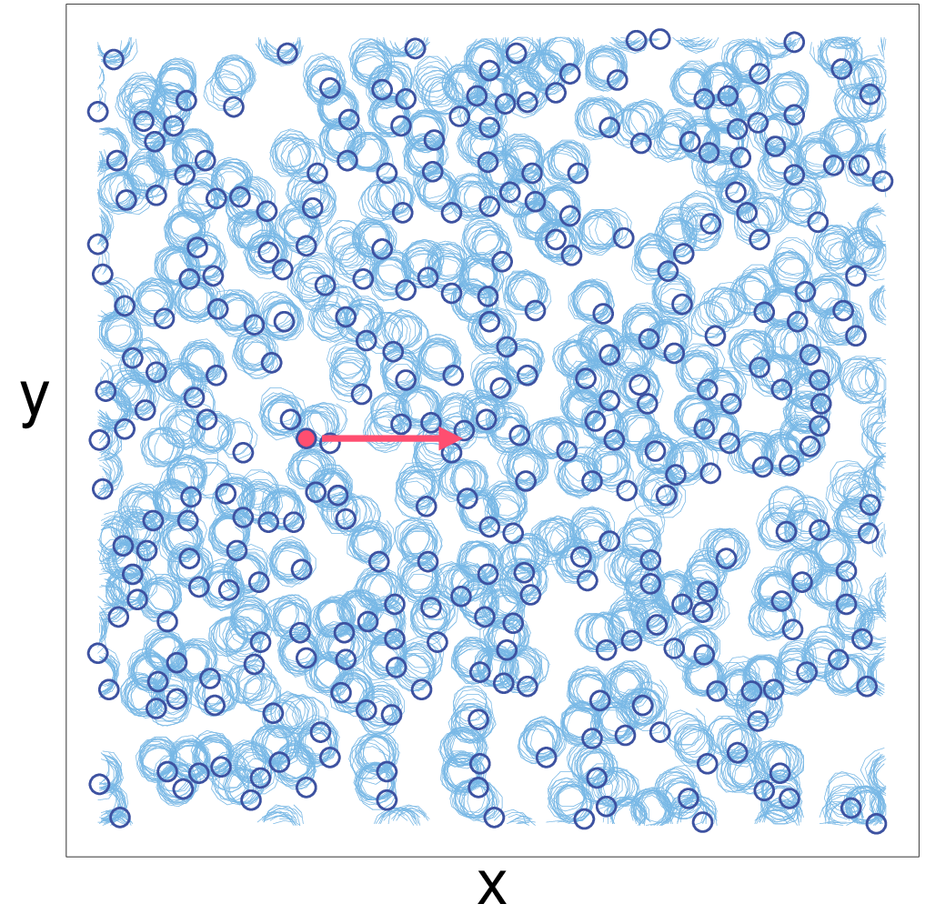
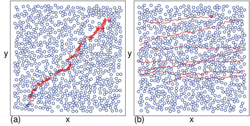
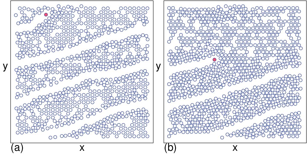
In Fig. 1 we show an image of the system highlighting the chiral disk locations and trajectories over a fixed period of time
for a system with ϕ = 0.181, A = 2.5, ω = 0.006, and a thermal force of FT = 2.0. The disks execute circular orbits, and the
center of mass of each circular orbit has a diffusive behavior. The red disk is the probe particle, which does not
experience a circular drive but instead moves under a force FD applied in the x direction, as indicated by the
arrow.
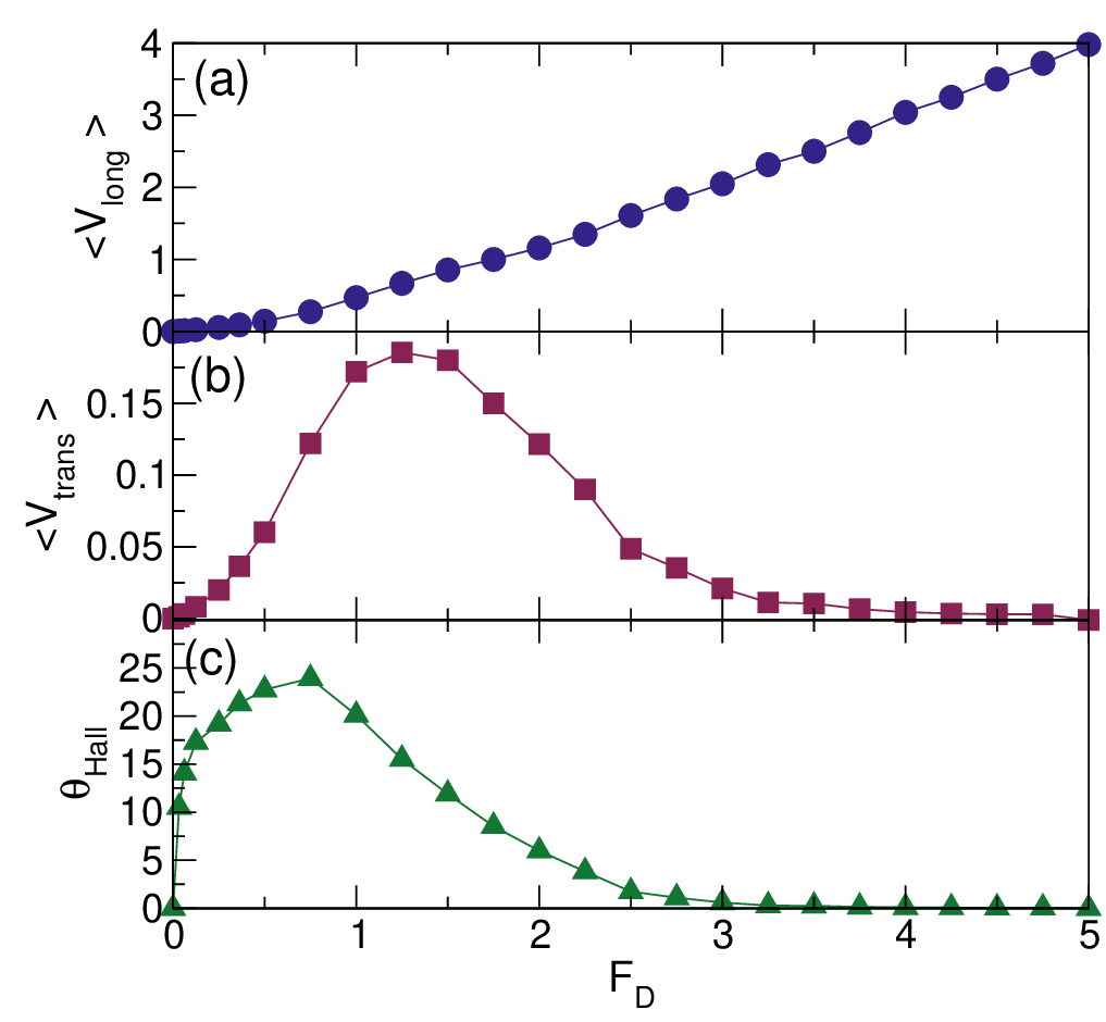
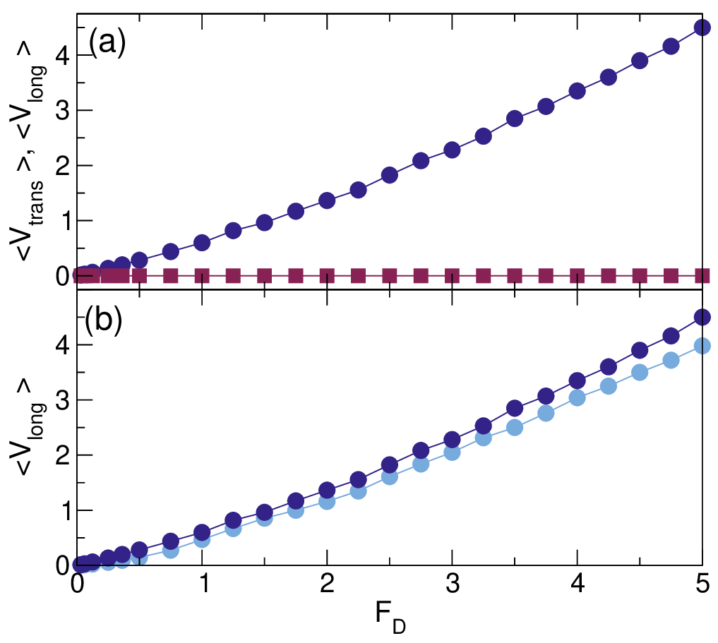
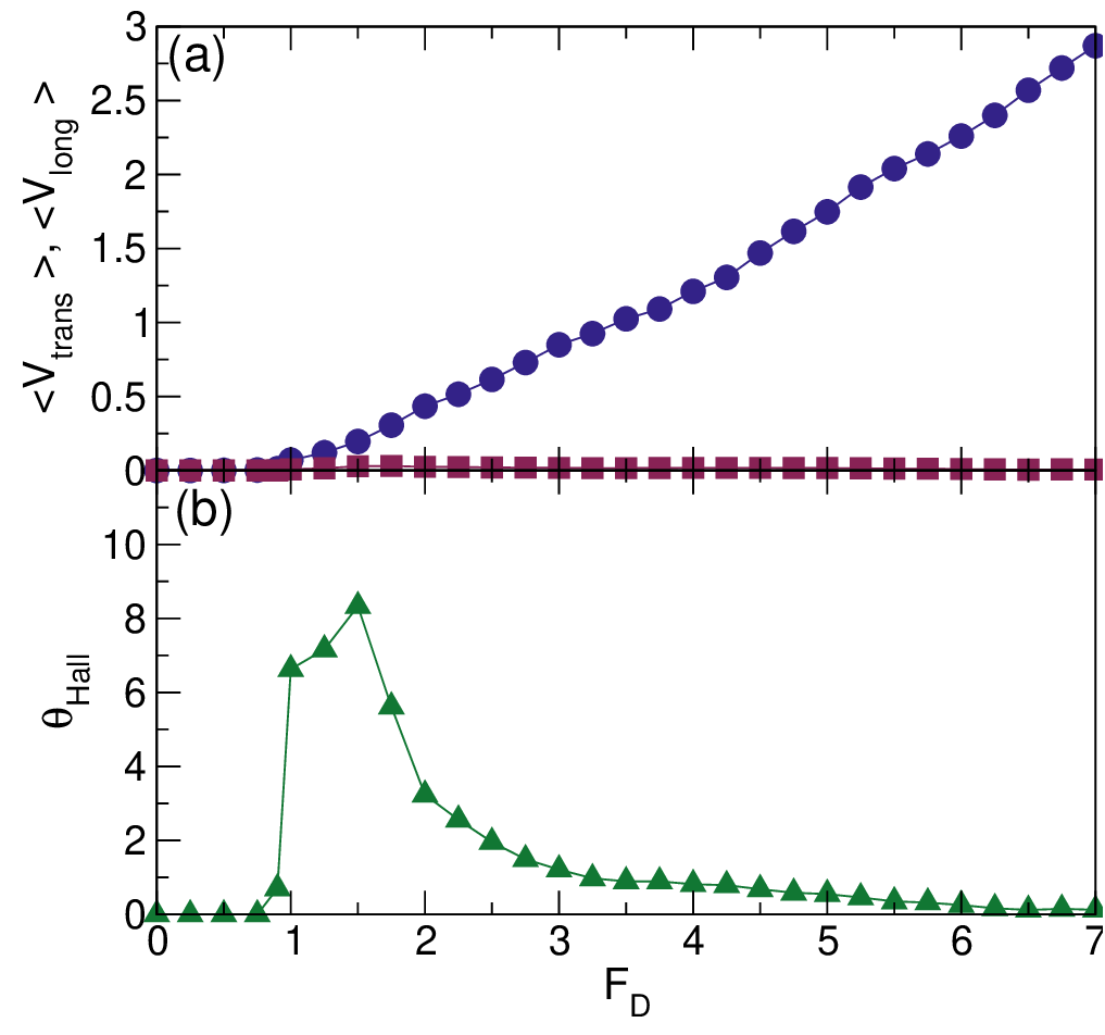
In Fig. 2(a,b) we plot ⟨V long⟩ and ⟨V trans⟩, respectively, versus FD in a system with ϕ = 0.424, A = 2.5, and
ω = 0.006. Here ⟨V long⟩ monotonically increases with increasing FD and there is no threshold for motion,
while ⟨V trans⟩ increases with increasing drive at low FD before reaching a maximum near FD = 1.25 and
then decreasing again. Since both the longitudinal and transverse velocities are finite, the driven particle is
moving at an angle with respect to drive direction, similar to the Hall effect found for the motion of a charged
particle in a magnetic field. We plot the Hall angle θHall = tan-1(⟨V trans⟩∕⟨V long⟩) versus FD in Fig. 2(c). The
maximum value of θHall = 23∘ occurs at FD = 0.75, a drive smaller than the value of FD = 1.26 at which the
maximum in ⟨V trans⟩ appears. For higher drives, θHall gradually deceases, reaching a value close to zero for
FD > 4.0.
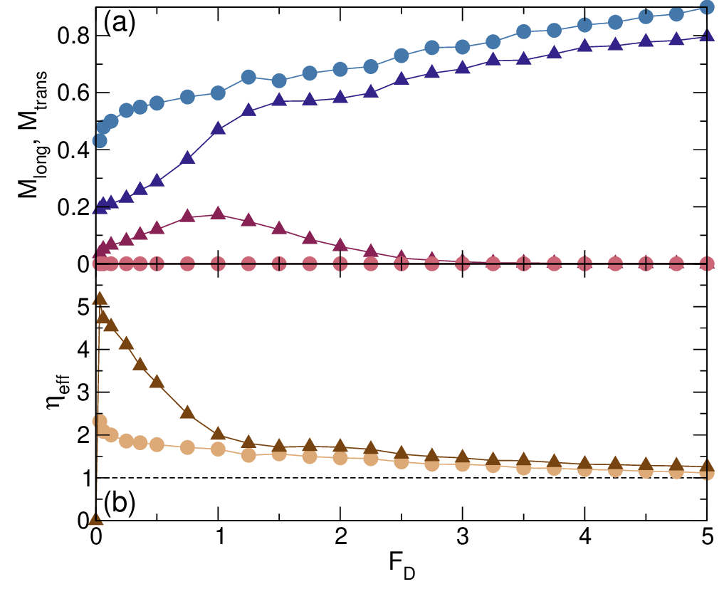
We measure the longitudinal mobility Mlong = ⟨V long⟩∕FD and transverse mobility Mtrans = ⟨V trans⟩∕FD for the system
in Fig. 2 and show the resulting curves in Fig. 3(a). Starting from a small value, Mlong increases with increasing FD until it
approaches the free-flow limit of Mlong = 1 at high drives. In contrast, Mtrans increases to a maximum value of Mtrans ≈ 0.2
near FD = 1.0 and then decreases to Mtrans = 0 at high drives. For comparison, in Fig. 3(a) we also plot the behavior of
Mlong and Mtrans in the A = 0 or inactive limit, where Mtrans = 0 for all values of FD. The value of Mlong is always higher
in the inactive system than in the sample with finite chiral motion, indicating that the chiral motion increases
the effective damping or viscosity experienced by the moving probe particle. A current topic in many chiral
active matter systems is the question of odd viscosity response [22–24], but it is not clear exactly what the
signature of odd viscosity would be in the local driven probe system. In Fig. 3(b) we plot the effective damping
constant ηeff = 1∕⟨V ⟩ versus FD for the active and passive systems shown in Fig. 3(a). Here the net velocity is
given by ⟨V ⟩ = (⟨V trans⟩2 + ⟨V long⟩2)1∕2. The effective damping for A = 0 is largest at low FD and decreases
monotonically with increasing drive, gradually approaching the free-particle limit of η = 1 at high drives. When
we introduce finite activity, we find a large increase in ηeff at low drives FD < 1. This also means that the
viscosity of the active system is larger, indicating that the active rotation increases the net damping in the
system.
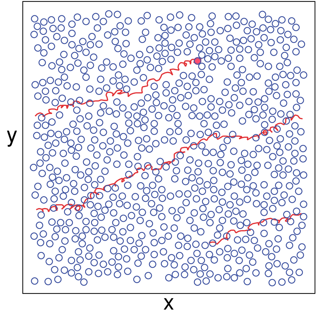
In Fig. 4 we illustrate the trajectory of the probe particle over a fixed time interval superimposed on a snapshot of the
instantaneous chiral disk locations for the system in Fig. 2 at FD = 1.0. The probe particle is moving at an angle of
approximately θHall = 20∘ with respect to the drive; however, there are local trajectory segments in which the Hall angle is
larger or smaller than average.
The chiral disks have an intrinsic rotation frequency of ω, and therefore the time required for each chiral disk to complete
one orbit is τP = 2π∕ω. The average spacing between chiral disks is a = 1∕ . When the probe particle comes into contact
with a chiral disk at small FD, the chiral disk can complete multiple rotations during the time required for the probe particle
to move out of interaction range since FDτP ≪ a. As a result, the average transverse force exerted on the probe particle
by the chiral disk is small and θHall is nearly zero. At high FD, the probe particle is moving rapidly in the
longitudinal direction and spends a very short time interacting with the chiral disks during a collision since
FDτP ≫ a, so once again the maximum transverse shift experienced by the probe particle is small and the Hall
angle is small. Between these limits, a resonance can occur. When ω = 0.006 and ϕ = 0.424, as in Fig. 2, the
average spacing between chiral disks is a = 1.35, and τP = 1047Δt, where Δt = 0.002 is the size of a simulation
time step. At FD = 0.75, the probe particle would move a distance FDτP = 1.57 during one chiral rotation
period in the absence of collisions with the chiral disks. Collisions reduce this travel distance to a value that is
close to a, so that on average the probe particle interacts with a given chiral disk for one rotation period.
This maximizes the chance that the chiral disk will exert a coordinated, monodirectional transverse force on
the probe particle, resulting in a significant transverse displacement. The maximum in θHall thus arises due
to a resonance between the chiral rotation time scale and the collision time scale. For higher ω at the same
chiral disk density ϕ, the peak in θHall shifts to higher values of FD. We can compare these results to the
behavior of θHall for driven skyrmions [49, 51, 52]. In the absence of pinning, θHall for the skyrmion system
has a constant value determined by the materials properties [49]. When pinning is present, θHall gradually
increases from zero at small FD, similar to what appears in Fig. 2(b). In the skyrmion case, θHall saturates to
the intrinsic value at large FD, while for the chiral liquid, θHall decreases as FD increases above the peak
value.
. When the probe particle comes into contact
with a chiral disk at small FD, the chiral disk can complete multiple rotations during the time required for the probe particle
to move out of interaction range since FDτP ≪ a. As a result, the average transverse force exerted on the probe particle
by the chiral disk is small and θHall is nearly zero. At high FD, the probe particle is moving rapidly in the
longitudinal direction and spends a very short time interacting with the chiral disks during a collision since
FDτP ≫ a, so once again the maximum transverse shift experienced by the probe particle is small and the Hall
angle is small. Between these limits, a resonance can occur. When ω = 0.006 and ϕ = 0.424, as in Fig. 2, the
average spacing between chiral disks is a = 1.35, and τP = 1047Δt, where Δt = 0.002 is the size of a simulation
time step. At FD = 0.75, the probe particle would move a distance FDτP = 1.57 during one chiral rotation
period in the absence of collisions with the chiral disks. Collisions reduce this travel distance to a value that is
close to a, so that on average the probe particle interacts with a given chiral disk for one rotation period.
This maximizes the chance that the chiral disk will exert a coordinated, monodirectional transverse force on
the probe particle, resulting in a significant transverse displacement. The maximum in θHall thus arises due
to a resonance between the chiral rotation time scale and the collision time scale. For higher ω at the same
chiral disk density ϕ, the peak in θHall shifts to higher values of FD. We can compare these results to the
behavior of θHall for driven skyrmions [49, 51, 52]. In the absence of pinning, θHall for the skyrmion system
has a constant value determined by the materials properties [49]. When pinning is present, θHall gradually
increases from zero at small FD, similar to what appears in Fig. 2(b). In the skyrmion case, θHall saturates to
the intrinsic value at large FD, while for the chiral liquid, θHall decreases as FD increases above the peak
value.
In Fig. 5(a) we plot ⟨V long⟩ and ⟨V trans⟩ versus FD for a non-chiral fluid with the same parameters as in Fig. 2 but with
A = 0. Here, ⟨V long⟩ increases monotonically with increasing FD, similar to the chiral system; however, ⟨V trans⟩ = 0 for all
values of FD, indicating that θHall = 0 and that it is the chiral motion of the bath particles that produces the Hall effect. We
find that ⟨V long⟩ is slightly lower in the chiral liquid than for the A = 0 passive disks, as shown in Fig. 5(b) where we compare
the ⟨V long⟩ versus FD curves for the A = 0 system from Fig. 5(a) and the A = 2.5 system from Fig. 2(a). The A = 2.5 curve
is lower for all FD, indicating that the chirality of the bath particles increases the longitudinal drag on the probe
particle.
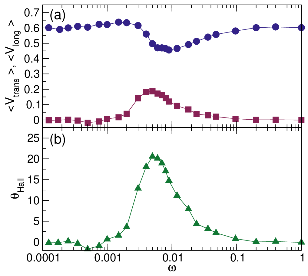
In Fig. 6(a) we plot ⟨V long⟩ and ⟨V trans⟩ versus ω for a system with ϕ = 0.424, A = 2.5, and FD = 1.0. Here there is a dip
in ⟨V long⟩ near ω = 0.008 that coincides with a peak in ⟨V trans⟩. The corresponding θHall versus ω appears in Fig. 6(b),
where the Hall angle reaches a maximum value of θHall = 23∘ near ω = 0.004. At low frequencies, the chiral disks are rotating
so slowly that the response is close to that of a passive fluid, while at high frequencies, the chiral orbits diminish in radius and
the system again behaves like a passive fluid.
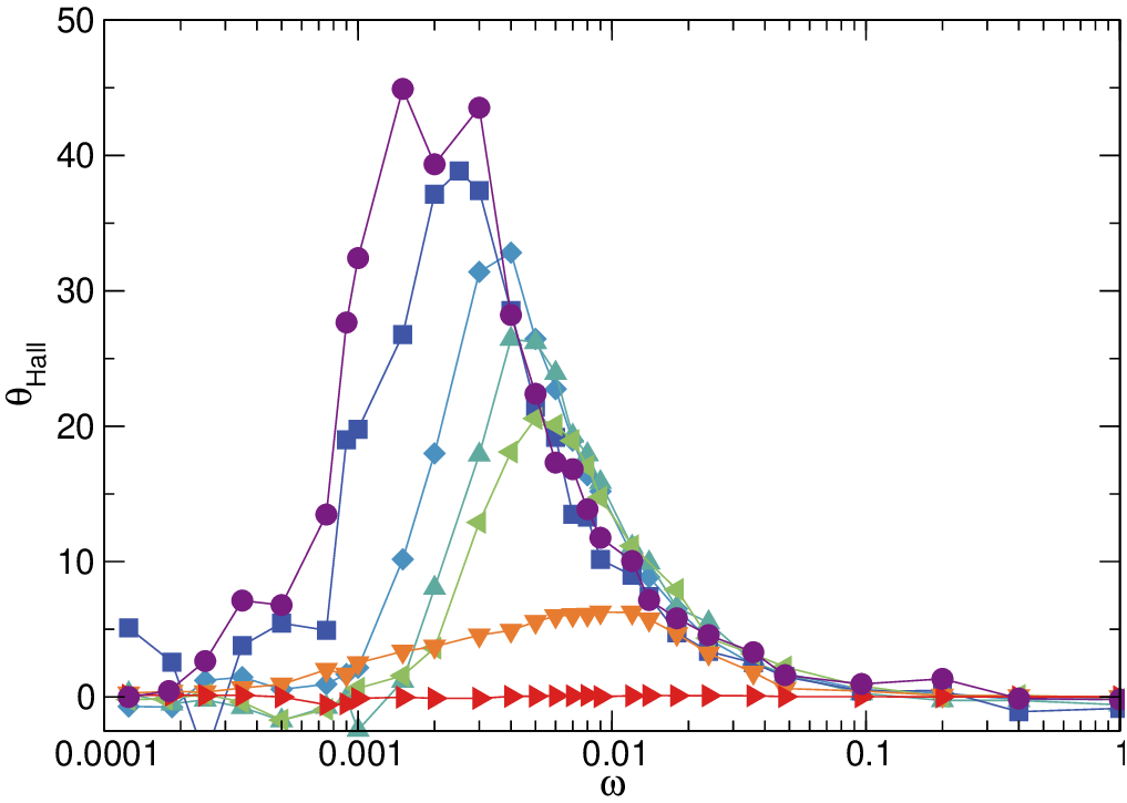
Figure 7 shows θHall versus ω for the system in Fig. 6 at FD values ranging from 0.125 to 4.0. The peak in θHall shifts to
higher values of ω with increasing FD since the chiral particles must rotate faster in order to meet the resonance condition
FDτP ~ a as FD increases. The maximum value of θHall increases with decreasing FD since the lower longitudinal velocity of
the probe particle at the peak in θHall produces a longer collision time and thus a greater transfer of momentum
from the chiral disks to the probe particle. The maximum Hall angle we observe at very low FD is close to
θHall = 45∘.
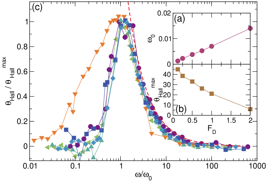
In Fig. 8(a) we plot the frequency ω0 at which θHall reaches its maximum value versus FD for the system in Fig. 7. We
find that ω0 increases linearly with increasing FD since it appears at a frequency for which a resonance occurs between the
time required for an active disk to complete a revolution and the time that separates consecutive collisions between the probe
particle and the active disks. The collision time is proportional to the probe velocity, which varies linearly with FD, and
therefore the resonant frequency ω0 also varies linearly with FD. We note that at lower FD, where the probe velocity
dependence on FD becomes nonlinear, this behavior breaks down. In Fig. 8(b) we plot θHallmax, the maximum value of the
Hall angle, versus FD. Here θHallmax decreases roughly linearly with increasing FD, with some deviation from
linearity at low values of FD. Using the linear fits of ω0 and θHallmax, we can collapse the curves from Fig. 7, as
shown in the plot of θHall∕θHallmax versus ω∕ω0 in Fig. 8(c). The dashed line in Fig. 8(c) is a fit to the form
θHall∕θHallmax ∝ 1∕ω* for ω* > 0, where ω*≡ ω∕ω0 - 1, showing that θHall decays as an inverse power law above the
resonant frequency.
In Fig. 9(a) we plot the trajectory of the probe particle and the positions of the chiral bath particles for the system in
Fig. 7 at FD = 0.25 and ω = 0.003, where θHall ≈ 45∘. During some time intervals, the probe particle moves at an angle of
nearly 90∘ with respect to the driving direction. Figure 9(b) illustrates the same sample at FD = 2.0 and ω = 0.012, where
the Hall angle is much smaller, θHall = 6.5∘.
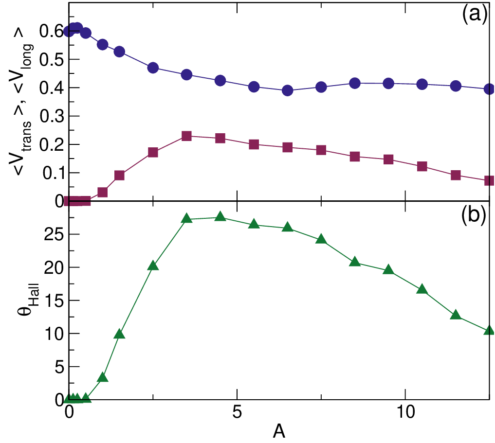
In Fig. 10(a) we show ⟨V trans⟩ and ⟨V long⟩ versus A for a system with ω = 0.006, FD = 1.0 and ϕ = 0.424. Here ⟨V long⟩ is
large in the A = 0 passive limit, and it decreases with increasing A, passing through a local minimum near A = 7.0. We find
that there is a threshold value Ac = 0.5 below which ⟨V trans⟩ = 0 and there is no transverse response, while a local maximum
in ⟨V trans⟩ appears at A = 4.0. We plot the corresponding θHall versus A in Fig. 10(b), where the maximum value of
θHall = 27∘ occurs near A = 4.0.
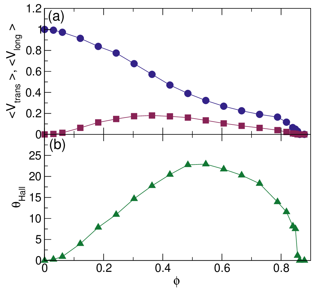
In Fig. 11(a) we plot ⟨V long⟩ and ⟨V trans⟩ versus ϕ for a system with A = 2.5, FD = 1.0 and ω = 0.006, while in Fig. 11(b)
we plot the corresponding θHall versus ϕ. At the lowest densities, the probe particle undergoes few collisions and moves in the
free flow limit with ⟨V long⟩∕FD = 1.0 and ⟨V trans⟩ = 0. As ϕ increases, the probe particle velocity gradually decreases,
dropping to zero near ϕ = 0.86, which is the effective jamming density for these parameters. The decrease in
the mobility of the probe particle with increasing density and the vanishing of the mobility as a jamming or
crystallization density is approached resembles what was found in previous studies of active rheology for non-chiral
passive disk systems [26, 27, 31, 32]. In those studies, ⟨V trans⟩ = 0 for all values of ϕ; however, for the chiral
disks we find an increase in ⟨V trans⟩ with increasing density at low values of ϕ, with a maximum in ⟨V trans⟩
appearing near ϕ = 0.35. This low density increase in the transverse response results from the increasing frequency
of collisions between the probe particle and the chiral disks, since it is these collisions that are responsible
for the transverse probe particle motion. For ϕ > 0.35, ⟨V trans⟩ decreases with increasing density due to a
crowding effect, and at jamming ⟨V trans⟩ drops to zero. The maximum value of θHall occurs at a higher density of
ϕ = 0.55.
We note that in principle it would be possible to perform a collapse of ⟨V trans⟩, ⟨V long⟩, and θHall for varied values of ω,
FD and A, similar to what is shown in Fig. 8. The number of independent variables can be reduced slightly since the behavior
as a function of A should be proportional to the behavior as a function of 1∕ωp, where ωp ∝ 1∕(FD + FDc) above the
resonance and ωp ∝ 1∕(FD - FDc) below the resonance. Here FDc is the value of the dc drive at which the
resonance occurs. Although we find that the drift velocity generally increases with FD, we do not observe
unbounded acceleration of the probe particle of the type that can occur in a Fermi acceleration process. This is
expected since the inclusion of even a small amount of dissipation can destroy the Fermi acceleration mechanism
[54].
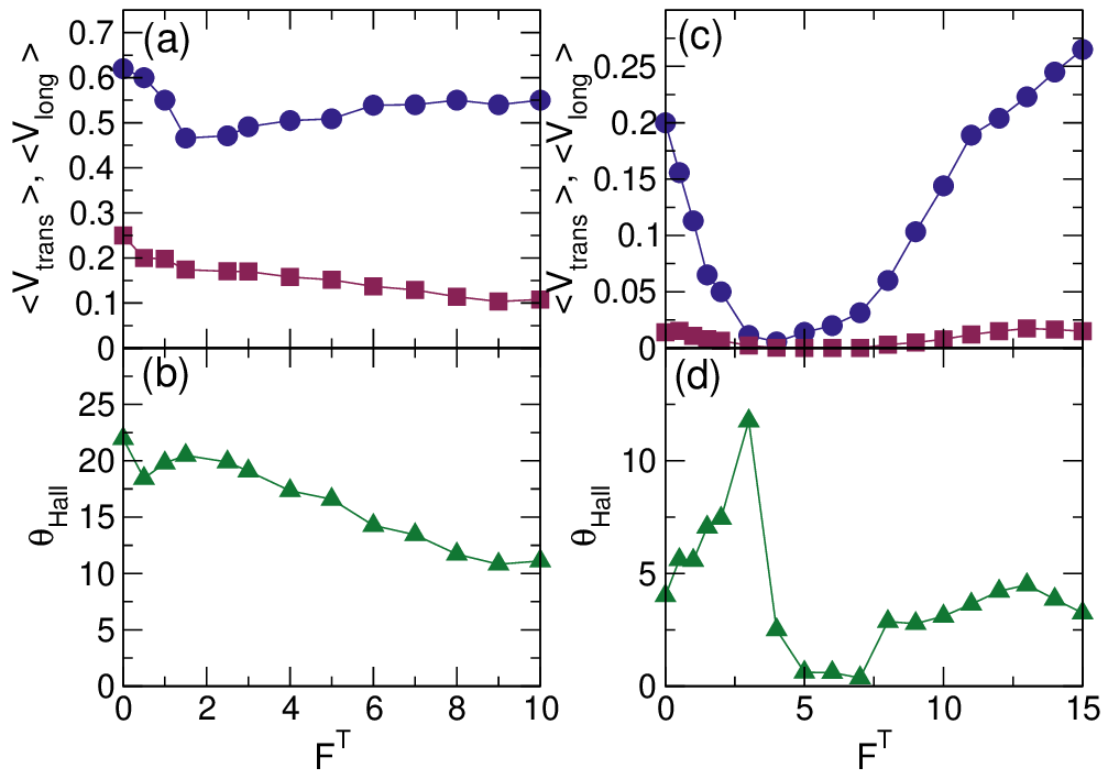
We next consider the effect of changing the magnitude of the thermal fluctuations. In Fig. 12(a) we plot ⟨V long⟩ and
⟨V trans⟩ versus FT for a system with FD = 1.0, ω = 0.006, A = 2.5, and ϕ = 0.424. At FT = 0, when the system is in the
granular limit, the probe particle leaves a low density wake behind it and ⟨V trans⟩ remains finite, indicating that thermal
fluctuations are not necessary to produce the Hall response. In Fig. 12(a), ⟨V trans⟩ monotonically decreases with increasing
FT; however, there is a local minimum in ⟨V long⟩ near FT = 2.0. The local minimum roughly coincides with the crossover
between low temperatures, where the probe leaves behind a low density wake, and higher temperatures, where the wake
rapidly refills with chiral disks. Figure 12(b) shows that the corresponding θHall versus FT has its maximum value at FT = 0,
with a smaller local maximum appearing near FT = 2.0. Above FT = 2.0, θHall decreases monotonically with increasing
FT.
In Fig. 13(a) we illustrate the probe particle motion for the system in Fig. 12(a) with ϕ = 0.424 at FT = 0, where the
probe particle moves at a finite Hall angle and leaves a low density wake in its path. The appearance of an empty region
behind the probe particle is similar to what has been observed for active rheology of non-thermal granular
materials below the jamming density [27, 32, 33], since in these systems there is no energy penalty for the
formation of a void. At finite FT, the chiral disks diffusively fill in the empty space. In Fig. 13(b) we show the
probe particle motion over the same time interval in a denser system with FT = 0 and ϕ = 0.67. The probe
particle does not translate as far due to the decrease in mobility; however, it still leaves behind a low density
wake.
In Fig. 12(c) we plot ⟨V long⟩ and ⟨V trans⟩ versus FT for a high density system with ϕ = 0.8482, ω = 0.006, A = 2.5, and
FD = 1.0, and in Fig. 12(d) we show the corresponding θHall versus FT. These parameters fall within a low mobility regime,
where the probe particle is not stuck but can only move relatively slowly through the chiral bath. At FT = 0, ⟨V long⟩≈ 0.2
and θHall = 4.5∘. As FT increases, both ⟨V long⟩ and ⟨V trans⟩ decrease, reaching a value that is close to zero near
FT = 4.0. This is a signature of a thermally-induced jamming transition that occurs when the thermal fluctuations
increase the effective size of the bath particles and raise the effective density of the system to the jamming
density. Such a transition can also be regarded as an example of a freezing by heating phenomenon in which the
thermal fluctuations can effectively freeze the disks into a jammed state [55]. If the thermal fluctuations are
finite but small, the chiral disks maintain their ordering in the jammed state and the probe particle slowly
makes its way through the resulting mostly triangular solid. As FT increases, the fluctuations become strong
enough to melt the chiral disk crystal. As a result, liquid behavior reappears and the probe particle mobility
rebounds, leading to the increase in both ⟨V long⟩ and ⟨V trans⟩ for FT > 6.0. The Hall angle θHall in Fig. 12(d)
passes through a local maximum near FT = 2.5 just before the onset of thermally-induced jamming, and it
drops nearly to zero within the jammed state when the probe particle motion becomes extremely slow. For
FT > 6.5, when the jammed state melts and the probe particle mobility increases, θHall increases back to its
pre-jammed level. These results indicate that a finite Hall effect can be observed even in non-thermal chiral
systems.
Near the jammed state at high chiral disk densities, the behavior of θHall depends strongly on FD and ω, since the probe
particle can only move through the jammed chiral disks if the driving force is larger than a depinning threshold Fc. A
monodisperse assembly of passive disks at T = 0 forms a triangular solid at a density of ϕ = 0.9. For densities close to but
below this solidification density, the addition of thermal fluctuations can induce freezing by heating or the formation of grain
boundaries and other defects, and the disks exhibit glassy or very slow dynamics for densities in the range 0.83 < ϕ < 0.9. In
our chiral disk system at FT = 2.0 and ϕ = 0.8482, the probe particle is mobile when FD = 1.0, but if we reduce FD we
find that there is a finite threshold drive Fc below which the probe particle is no longer able to move. This is
illustrated in Fig. 14(a), where we plot ⟨V long⟩ and ⟨V trans⟩ versus FD for a system with ϕ = 0.8482, ω = 0.006,
FT = 2.0, and A = 2.5. Here ⟨V long⟩ = ⟨V trans⟩ = 0 when FD < Fc, where the threshold force Fc = 0.6. In the
corresponding θHall versus FD curve shown in Fig. 14(b), we find that θHall = 0 for FD < 0.8, indicating
that within the window Fc < FD < 0.8, the probe particle has a finite longitudinal velocity but exhibits no
Hall effect. The Hall angle reaches its maximum value of θHall ≈ 8.5 near FD = 1.75, and gradually decreases
toward zero for higher drives. Since this system is at a finite temperature of FT = 2.0, the probe particle is best
described as undergoing a creep behavior at FD = 0.8. During long periods of time, the probe particle is pinned,
but there are occasional events in which the probe particle jumps to a new pinned location. Recent studies of
driven skyrmions [51, 56] showed that the Hall angle is zero in the creep regime and becomes finite at higher
drives when the skyrmions transition to continuous flow, similar to what we observe in Fig. 14; however, in the
skyrmion case, θHall saturates to the intrinsic value at high drives rather than decreasing back to zero as in
Fig. 14.
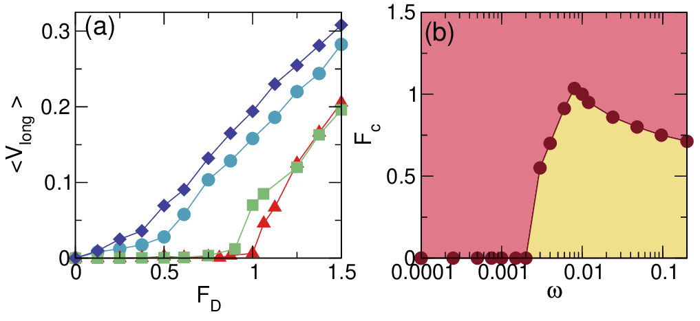
At high densities, we find that the threshold force Fc depends on the frequency at which the chiral disks rotate. In
Fig. 15(a) we plot ⟨V long⟩ versus FD in a system with A = 2.5, FT = 2.0, and ϕ = 0.8482 at ω = 0.008, 0.006, 0.003, and
0.001. The threshold for motion is finite at ω = 0.006 and ω = 0.008, and zero for ω = 0.003 and ω = 0.001. In Fig. 15(b) we
show Fc versus ω for the system from Fig. 15(a). For drives above Fc, the probe can flow through the sample, but for
drives below Fc, the probe particle is pinned. Here we find that Fc is finite only when ω > 0.003, and that
there is a local maximum in Fc near ω = 0.01. We note that the appearance of a finite depinning threshold for
a probe particle has been observed experimentally for systems in a high density or glassy regime [26, 57].
For the passive A = 0 limit in our system, we are always below the non-active jamming density of 0.9, so the
inclusion of activity can be viewed as effectively increasing the density of the particles. An open question is
what effect the chiral activity would have on a system that is above the passive jamming density. For example,
addition of activity could increase or decrease the critical depinning force. Our results indicate that at higher disk
densities, the activity level of the chiral disks can be used to control a transition from jammed to unjammed
behavior.
IV. Summary
We have numerically examined the motion of a probe particle driven through a chiral liquid composed of circularly moving
disks. In the absence of chirality, the probe particle drifts only in the direction of drive so there is no Hall effect; however,
when the bath particles are chiral, both the longitudinal and transverse velocities of the probe particle are
finite. Since a portion of the probe particle motion is perpendicular to the drive direction, the probe particle
exhibits a finite Hall angle similar to what is observed for a charged particle moving in a magnetic field or for
driven skyrmion systems. We find that the Hall angle has a non-monotonic dependence on the probe particle
driving force and the amplitude and frequency of the chiral disk motion. At low drives, the probe particle can
undergo multiple collisions with an individual chiral bath particle, reducing the Hall angle, while at high drives
the collisions between the probe and chiral bath particles are very brief, which again reduces the magnitude
of the Hall angle. An optimal Hall angle occurs when the time between collisions of the probe particle with
consecutive chiral bath particles is roughly equal to the time required for a chiral bath particle to complete a
single rotation. We find that the Hall angle can reach values as large as θHall = 45∘ and that the Hall effect
persists in the zero temperature or granular limit. When the chiral disk activity is fixed, the Hall angle is
maximized at an optimal chiral disk density, while the probe particle velocity in both the longitudinal and
transverse directions drops to zero when the chiral disks reach the jamming density, which is dependent on the
frequency of the chiral motion. At low frequencies, the depinning threshold is zero and the probe particle is
able to move under all applied drives, while at higher frequencies there is a finite depinning threshold, and
for drives below this threshold, the probe particle is pinned. We compare our results with those obtained for
skyrmions moving over random disorder, where drive-dependent Hall angles that increase with increasing drive are
observed. In the skyrmion case, the Hall angle saturates to the clean limit at high drives, whereas for the chiral
liquid we consider here, the Hall angle decreases to zero at high drives. Our results could be tested by driving
probe particles through active chiral colloidal spinners, chiral granular matter, or even chiral robot swarms.
Additionally, these results could be relevant to other systems that mimic chiral active baths, such as driving a single
skyrmion through an array of other skyrmions or driving a single particle through an array of optical or fluid
vortices.
Note added– In the course of completing this work, we became aware of the work of Kumar et al. [58] on the motion of
spinning probe particles through granular matter, where they report the onset of a Magnus like effect including a lift
force.
Acknowledgments
We gratefully acknowledge the support of the U.S. Department of Energy through the LANL/LDRD program for this work.
This work was supported by the US Department of Energy through the Los Alamos National Laboratory. Los Alamos
National Laboratory is operated by Triad National Security, LLC, for the National Nuclear Security Administration of the U.
S. Department of Energy (Contract No. 892333218NCA000001).
[1] H. Löwen, Chirality in microswimmer motion: From circle swimmers to active turbulence, Eur. Phys. J. Spec. Top.
225, 2319 (2016).
[2] C. Bechinger, R. Di Leonardo, H. Löwen, C. Reichhardt, G. Volpe, and G. Volpe, Active Brownian particles in complex
and crowded environments, Rev. Mod. Phys. 88, 045006 (2016).
[3] P. Tierno, T. Johansen, and T. Fischer, Localized and delocalized motion of colloidal particles on a magnetic bubble
lattice, Phys. Rev. Lett. 99, 038303 (2007).
[4] F. Kümmel, B. ten Hagen, R. Wittkowski, I. Buttinoni, R. Eichhorn, G. Volpe, H. Löwen, and C. Bechinger, Circular
motion of asymmetric self-propelling particles, Phys. Rev. Lett. 110, 198302 (2013).
[5] M. Han, J. Yan, S. Granick, and E. Luijten, Effective temperature concept evaluated in an active colloid mixture, Proc.
Natl. Acad. Sci. (USA) 114, 7513 (2017).
[6] G. Kokot, S. Das, R. G. Winkler, G. Gompper, I. S. Aranson, and A. Snezhko, Active turbulence in a gas of
self-assembled spinners, Proc. Natl. Acad. Sci. (USA) 114, 12870 (2017).
[7] W.R. DiLuzio, L. Turner, M. Mayer, P. Garstecki, D.B. Weibel, H.C. Berg, and G.M. Whitesides, Escherichia coli
swim on the right-hand side, Nature (London) 435, 1271 (2005).
[8] H. P. Nguyen, D. Klotsa, M. Engel, and S. C. Glotzer, Emergent collective phenomena in a mixture of hard shapes
through active rotation, Phys. Rev. Lett. 112, 075701 (2014).
[9] B. C. van Zuiden, J. Paulose, W. T. M. Irvine, D. Bartolo, and V. Vitelli, Spatiotemporal order and emergent edge
currents in active spinner materials, Proc. Natl. Acad. Sci. (USA) 113, 12919 (2016).
[10] D. Banerjee, A. Souslov, A. G. Abanov, and V. Vitelli, Odd viscosity in chiral active fluids, Nature Commun. 8, 1573
(2017).
[11] A. Aubret, M. Youssef, S. Sacanna, and J. Palacci, Targeted assembly and synchronization of self-spinning microgears,
Nature Phys. 14, 1114 (2018).
[12] K. Dasbiswas, K. K. Mandadapu, and S. Vaikuntanathan, Topological localization in out-of-equilibrium dissipative
systems, Proc. Natl. Acad. Sci. (USA) 115, E9031 (2018).
[13] B. Liebchen and D. Levis, Collective behavior of chiral active matter: pattern formation and enhanced flocking, Phys.
Rev. Lett. 119, 058002 (2017).
[14] B.-Q. Ai, Z.-G. Shao, and W.-R. Zhong, Mixing and demixing of binary mixtures of polar chiral active particles, Soft
Matter 14, 4388 (2018).
[15] C. Reichhardt and C. J. O. Reichhardt, Reversibility, pattern formation, and edge transport in active chiral and passive
disk mixtures, arXiv:1812.04150 J. Chem. Phys. 150, 064905 (2019).
[16] S. I. Denisov, T. V. Lyutyy, V. V. Reva, and A. S. Yermolenko, Temperature effects on drift of suspended single-domain
particles induced by the Magnus force, Phys. Rev. E 97, 032608 (2018).
[17] A. Maitra and M. Lenz, Spontaneous rotation can stabilise ordered chiral active fluids, Nat. Commun. 10, 920 (2019).
[18] C. Scholz, M. Engel, and T. Pöschel, Rotating robots move collectively and self-organize, Nature Commun. 9, 931
(2018).
[19] N. Nagaosa and Y. Tokura, Topological properties and dynamics of magnetic skyrmions, Nature Nanotechnol. 8, 899
(2013).
[20] U. Ritzmann, S. von Malottki, J.-V. Kim, S. Heinze, J. Sinova, and B. Dupe, Trochoidal motion and pair generation
in skyrmion and antiskyrmion dynamics under spin-orbit torques, Nature Electron. 1, 451 (2018).
[21] H. Goldstein, C.P. Poole, and J.L. Safko, Classical Mechanics, 3rd Edition (Addison-Wesley, 2002).
[22] V. Soni, E. Bililign, S. Magkiriadou, S. Sacanna, D. Bartolo, M. J. Shelley, and W. T. M. Irvine, The free surface of a
colloidal chiral fluid: waves and instabilities from odd stress and Hall viscosity, arXiv:1812.09990 (unpublished).
[23] S. Ganeshan and A. G. Abanov, Odd viscosity in two-dimensional incompressible fluids, Phys. Rev. Fluids 2, 094101
(2017).
[24] A. Souslov, K. Dasbiswas, M. Fruchart, S. Vaikuntanathan, and V. Vitelli, Topological waves in fluids with odd viscosity,
Phys. Rev. Lett. 122, 128001 (2019).
[25] M. B. Hastings, C. J. Olson Reichhardt, and C. Reichhardt, Depinning by fracture in a glassy background, Phys. Rev.
Lett. 90, 098302 (2003).
[26] P. Habdas, D. Schaar, A. C. Levitt, and E. R. Weeks, Forced motion of a probe particle near the colloidal glass
transition, Europhys. Lett. 67, 477 (2004).
[27] J. A. Drocco, M. B. Hastings, C. J. Olson Reichhardt, and C. Reichhardt, Multiscaling at Point J: Jamming is a critical
phenomenon, Phys. Rev. Lett. 95, 088001 (2005).
[28] T. M. Squires and J. F. Brady, A simple paradigm for active and nonlinear microrheology, Phys. Fluids 17, 073101
(2005).
[29] L. G. Wilson and W. C. K. Poon, Small-world rheology: an introduction to probe-based active microrheology, Phys.
Chem. Chem. Phys. 13, 10617 (2011).
[30] R. N. Zia, Active and passive microrheology: theory and simulation, Ann. Rev. Fluid Mech. 50, 371 (2018).
[31] R. Candelier and O. Dauchot, Journey of an intruder through the fluidization and jamming transitions of a dense
granular media, Phys. Rev. E 81, 011304 (2010).
[32] C. J. Olson Reichhardt and C. Reichhardt, Fluctuations, jamming, and yielding for a driven probe particle in disordered
disk assemblies, Phys. Rev. E 82, 051306 (2010).
[33] E. Kolb, P. Cixous, N. Gaudouen, and T. Darnige, Rigid intruder inside a two-dimensional dense granular flow: Drag
force and cavity formation, Phys. Rev. E 87 032207 (2013).
[34] Y. Takehara and K. Okumura, High-velocity drag friction in granular media near the jamming point, Phys. Rev. Lett.
112, 148001 (2014).
[35] A.M. Puertas and T. Voigtmann, Microrheology of colloidal systems, J. Phys.: Condens. Matter 26, 243101 (2014).
[36] A. Fiege, M. Grob, and A. Zippelius, Dynamics of an intruder in dense granular fluids, Granular Matter 14, 247 (2012).
[37] I. Gazuz, A. M. Puertas, Th. Voigtmann, and M. Fuchs, Active and nonlinear microrheology in dense colloidal
suspensions, Phys. Rev. Lett. 102, 248302 (2009).
[38] R. N. Zia and J. F. Brady, Single-particle motion in colloids: force-induced diffusion, J. Fluid Mech. 658, 188 (2010).
[39] D. Winter, J. Horbach, P. Virnau, and K. Binder, Active nonlinear microrheology in a glass-forming Yukawa fluid,
Phys. Rev. Lett. 108, 028303 (2012).
[40] R. P. A. Dullens and C. Bechinger, Shear thinning and local melting of colloidal crystals, Phys. Rev. Lett. 107, 138301
(2011).
[41] C. Reichhardt and C. J. Olson Reichhardt, Local melting and drag for a particle driven through a colloidal crystal,
Phys. Rev. Lett. 92, 108301 (2004).
[42] C. Mejía-Monasterio and G. Oshanin, Bias- and bath-mediated pairing of particles driven through a quiescent medium,
Soft Matter 7, 993 (2011).
[43] O. Bénichou, P. Illien, C. Mejía-Monasterio, and G. Oshanin, A biased intruder in a dense quiescent medium: looking
beyond the force–velocity relation, J. Stat. Mech. 2013, P05008 (2013).
[44] P. Illien, O. Bénichou, G. Oshanin, A. Sarracino, and R. Voituriez, Nonequilibrium fluctuations and enhanced diffusion
of a driven particle in a dense environment, Phys. Rev. Lett. 120, 200606 (2018).
[45] E. W. J. Straver, J. E. Hoffman, O. M. Auslaender, D. Rugar, and K. A. Moler, Controlled manipulation of individual
vortices in a superconductor, Appl. Phys. Lett. 93, 172514 (2008).
[46] O. M. Auslaender, L. Luan, E. W. J. Straver, J. E. Hoffman, N. C. Koshnick, E. Zeldov, D. A. Bonn, R. Liang, W. N.
Hardy, and K. A. Moler, Mechanics of individual isolated vortices in a cuprate superconductor, Nature Phys. 5, 35 (2009).
[47] X. Ma, C. J. O. Reichhardt, and C. Reichhardt, Manipulation of individual superconducting vortices and stick-slip
motion in periodic pinning arrays, Phys. Rev. B 97, 214521 (2018).
[48] C. Reichhardt and C. J. Olson Reichhardt, Active microrheology in active matter systems: Mobility, intermittency, and
avalanches, Phys. Rev. E 91, 032313 (2015).
[49] C. Reichhardt, D. Ray, and C. J. Olson Reichhardt, Collective transport properties of driven skyrmions with random
disorder, Phys. Rev. Lett. 114, 217202 (2015).
[50] C. Reichhardt and C. J. O. Reichhardt, Noise fluctuations and drive dependence of the skyrmion Hall effect in disordered
systems, New J. Phys. 18, 095005 (2016).
[51] W. Jiang, X. Zhang, G. Yu, W. Zhang, X. Wang, M. B. Jungfleisch, J. E. Pearson, X. Cheng, O. Heinonen, K. L.
Wang, Y. Zhou, A. Hoffmann, and S. G. E. te Velthuis, Direct observation of the skyrmion Hall effect, Nature Phys. 13,
162 (2017).
[52] K. Litzius, I. Lemesh, B. Krüger, P. Bassirian, L. Caretta, K. Richter, F. Büttner, K. Sato, O. A. Tretiakov, J. Förster,
R. M. Reeve, M. Weigand, I. Bykova, H. Stoll, G. Schütz, G. S. D. Beach, and M. Kläui, Skyrmion Hall effect revealed by
direct time-resolved X-ray microscopy, Nature Phys. 13, 170 (2017).
[53] S. Woo, K. M. Song, X. Zhang, Y. Zhou, M. Ezawa, X.-X. Liu, S. Finizio, J. Raabe, N. J. Lee, S.-I. Kim, S.-Y. Park, Y.
Kim, J.-Y. Kim, D. Lee, O. Lee, J. W. Choi, B.-C. Min, H. C. Koo, and J. Chang, Current-driven dynamics and inhibition
of the skyrmion Hall effect of ferrimagnetic skyrmions in GdFeCo films, Nature Commun. 9, 959 (2018).
[54] E. D. Leonel and L. A. Bunimovich, Suppressing Fermi acceleration in a driven elliptical billiard, Phys. Rev. Lett. 104,
224101 (2010).
[55] D. Helbing, I. J. Farkas, and T. Vicsek, Freezing by heating in a driven mesoscopic system, Phys. Rev. Lett. 84, 1240
(2000).
[56] C. Reichhardt and C. J. O. Reichhardt, Thermal creep and the skyrmion Hall angle in driven skyrmion crystals, J.
Phys.: Condens. Matter 31, 07LT01 (2019).
[57] N. Senbil, M. Gruber, C. Zhang, M. Fuchs, and F. Scheffold, Observation of strongly heterogeneous dynamics at the
depinning transition in a colloidal glass, Phys. Rev. Lett. 122, 108002 (2019).
[58] S. Kumar, M. Dhiman, and K. A. Reddy, Magnus effect in granular media, Phys. Rev. E 99, 012902 (2019).
Back to Home