Physical Review Letters 120, 027204 (2018)

Inner Phases of Colloidal Hexagonal Ice

A. Libál1,2, C. Nisoli1, C.J.O. Reichhardt1, and C. Reichhardt1

1Theoretical Division and Center for Nonlinear Studies, Los Alamos National Laboratory, Los Alamos, New Mexico 87545, USA
2Mathematics and Computer Science Department, Babes-Bolyai University, Cluj 400084, Romania

(Received 14 September 2017; published 12 January 2018)

Using numerical simulations that mimic recent experiments on hexagonal colloidal ice, we show that colloidal hexagonal artificial spin ice exhibits an inner phase within its ice state that has not been observed previously. Under increasing colloid-colloid repulsion, the initially paramagnetic system crosses into a disordered ice-regime, then forms a topologically charge ordered state with disordered colloids, and finally reaches a three-fold degenerate, ordered ferromagnetic state. This is reminiscent of, yet distinct from, the inner phases of the magnetic kagome spin ice analog. The difference in the inner phases of the two systems is explained by their difference in energetics and frustration.
Introduction
Simulation
Results
Discussion
Conclusion
References


Introduction. Artificial spin ice (ASI) systems have been attracting increasing interest as frameworks for studying frustration or degeneracy and for revealing emergent exotic behaviors [1,2,3]. Among the most studied ASIs are nano-scale magnets arranged in square [1,4,5,6,7,8,9], hexagonal [1,10,11,12,13], or other geometries [14,15,16,17,18,19,20,21]. Each individual magnet behaves like a binary spin degree of freedom and adopts, to a nearest-neighbor (NN) approximation, an ice-rule configuration that minimizes the topological charge qn, defined as the absolute difference between the n spins pointing in and no spins pointing out of each vertex. This configuration can be ordered, as in square ice [1,4], or it can be a disordered manifold with non-zero entropy density. Moving beyond the NN approximation, inner phases and transitions appear within the disordered ice manifold. In hexagonal ice, each vertex is surrounded by vn=3 spins and the ice rule corresponds to n=1, no=2 (qn=2nvn=−1) or n=2, no=1 (qn=+1). In disordered hexagonal or kagome ice, inner phases corresponding to charge ordering (CO) within spin disorder (the "spin ice II" or SI2 phase) and to long range order (LRO) have been reported [22,23] and experimentally investigated [10,12,24,25].
Fig1.png
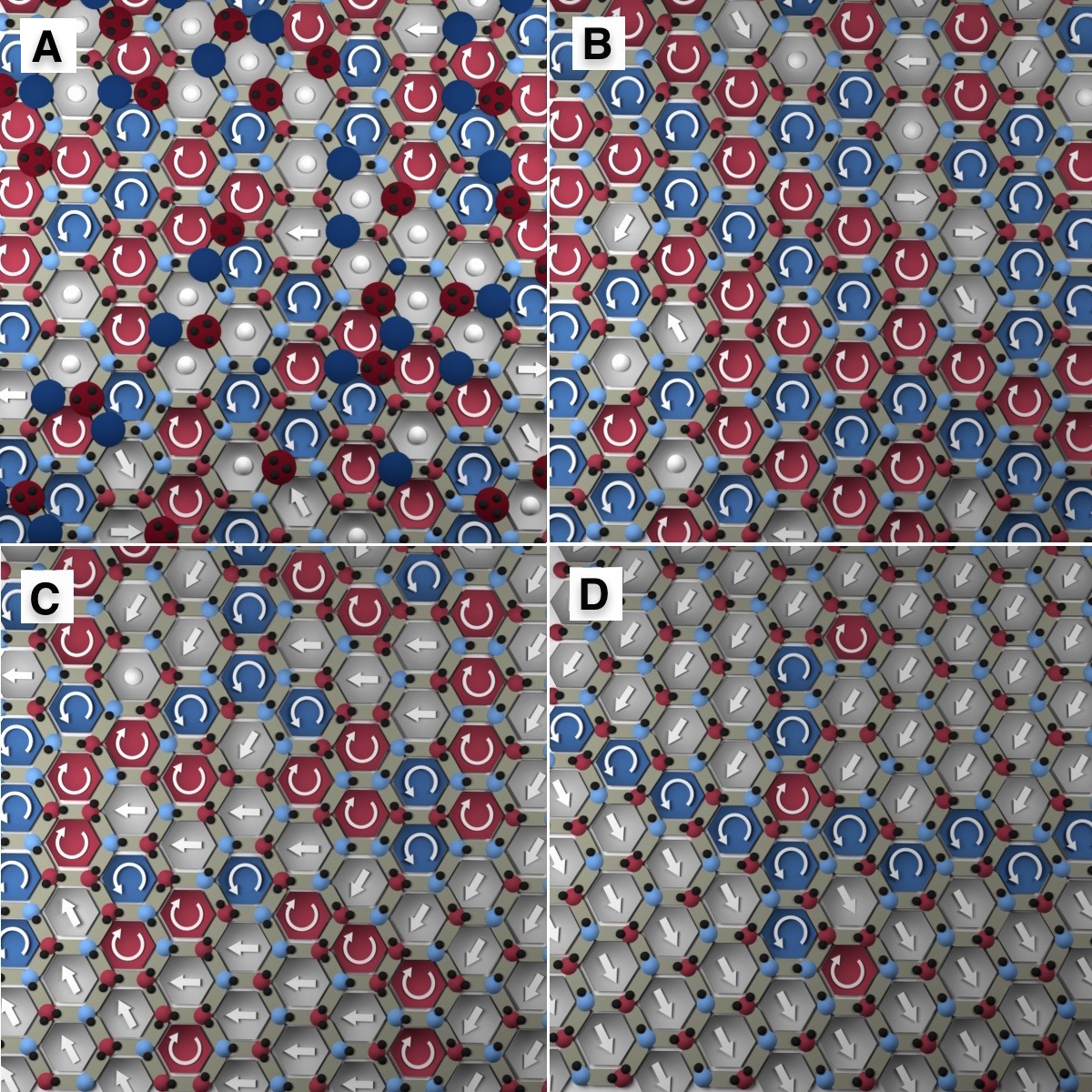
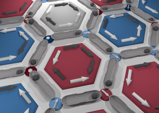
Figure 1: Schematic of the particle-based hexagonal artificial spin ice. Each double well trap (light grey) holds a single paramagnetic colloid (dark grey dots). The hexagonal plaquettes contain arrows indicating the pseudospin σi of the adjacent traps, colored according to the chirality χi=+1 (clockwise, dark grey) or χi=−1 (counter-clockwise, white). The plaquettes are colored according to their net spin chirality χ: clockwise (red), counter-clockwise (blue), or achiral (grey). Colored disks are guides to the eye and indicate the vertex type: n=0 or 0-in (dark blue), n=1 (light blue), n=2 (light red), and n=3 (dark red); arrows (of length 2) or dots (of length 0) on the disks indicate the vectorial sum si of the pseudospins adjacent to each vertex.
Another interesting class of ASIs that resemble water ice consists of an array of double-well traps that each capture one particle, as illustrated in Fig. 1. The traps are arranged in a square or hexagonal ice geometry with vn=4 or vn=3 traps, respectively, around each vertex, and the particle-particle interactions are repulsive. Particle-based ASIs have been studied numerically for colloids [26,27,28,29,30,31,32], skyrmions [33], and vortices in type-II superconductors [34], and have been realized experimentally in superconductors [35,36,37,38] and for paramagnetic colloids on grooved surfaces [39,40,41].
Particle-based ASIs can be described in the same way as magnetic spin ices by defining a pseudospin σi lying along the trap axis and pointing toward the particle [26,34,27]. Although the particle and magnetic ASIs differ greatly both in energetics and frustration, both obey the ice rules at low energy, though for different reasons [27]. Consider for definiteness vn=3 magnetic and colloidal hexagonal or kagome ASIs, which both obey the ice rule through a local minimization of qn. The NN energy En of magnetic dipoles impinging into a vertex is proportional to the square of the charge, Enqn2. Thus the ice rule (qn=±1 allowed and qn=±3 forbidden) is enforced locally by energy minimization. For the colloids, Enn(n−1), and the vertex energetics favors large negative charges (qn=−3). Thus the ice rule obeying particle-based ASI minimizes the global energy of the system rather than the local energy, as in its magnetic counterpart [27].
An open question is how far the similarities between the particle-based and magnetic ASIs extend. Here we explore the types of ice rule states that occur in particle-based ASI and how they relate to the CO and LRO of magnetic systems. We simulate paramagnetic colloids held gravitationally in double-well etched grooves, similar to those used in recent experiments [40,41]. The colloids repel each other with interaction ∝ B2/r4 when a perpendicular magnetizing field B is applied. The strength of the spin-spin interactions can be tuned easily by varying B, permitting us to map different ice phases. For weak interactions the system is in a paramagnetic state containing qn=±3 charges, but we find that for higher interaction strengths the system enters an ice-rule phase with no qn=±3 charges. As B is increased further, a charge ordering regime emerges in which the colloids remain disordered, and the order gradually increases until the system forms domains of three-fold symmetric ferromagnetic order.
Simulation- We conduct Brownian dynamics simulations of the particle-based hexagonal ASI comprised of Np=2700 magnetically interacting colloids with diameter 1μm placed in an array of Nt=2700 etched double-well grooves. There are Npl = 900 hexagonal plaquettes of side ah=3μm arranged on a 15×20 lattice with dimensions of 135μm ×155.88μm, and we use periodic boundary conditions in both the x and y directions. Each plaquette is surrounded by six double-well traps of length at=2.8μm, as illustrated in Fig. 1, giving a total of Nv=1800 vertices. A confining spring force Fc1 acts perpendicularly to the elongated direction of the trap, and each end of the trap contains a confining parabolic attractive well exerting force Fc2 with a spring constant of 2.2pN/μm representing the gravitationally induced attraction. A repulsive harmonic barrier Fh of magnitude 2.11 pN corresponding to a barrier of height 3.32μm separates the attractive wells. The combined substrate forces are written as Fs=Fc1+Fc2+Fh. Magnetization of the colloids in the z direction produces a repulsive particle-particle interaction force Fpp(r)=Acr/r4 with Ac=3×10⁶χm2 V2 B2/(πμm) for colloids a distance r apart. Here χm is the magnetic susceptibility, μm is the magnetic permeability, V is the colloid volume, B is the magnetic field in mT, and all distances are measured in μm. For the paramagnetic colloids in Ref. [40,41], this gives |Fpp|=6.056 pN for r=3μm at B=40 mT, the maximum field we consider. The dynamics of colloid i are obtained using the following discretized overdamped equation of motion:
1

μ
ri

t
=   ⎛


2

Dt
 
kB T N[0,1] + Fppi + Fsi
(1)
where the diffusion constant D=36000μm2/s, the mobility μ = 8.895 μm pN/s, the simulation time step ∆t = 1ms, and where N[0,1] is a Gaussian distributed random number with mean 0 and variance 1. The first term on the right is a thermal force consisting of Langevin kicks of magnitude FT=0.95 pN corresponding to a temperature of t=20°C. Each trap is initially filled with a single colloid placed in a randomly chosen well. We increase B linearly from B = 0 mT to B = 40 mT, consistent with the experimental range [39]. Unless otherwise noted, we average the results over 100 simulations performed with different random seeds. Around a hexagonal plaquette, there is a pseudospin to the right and left of each vertex. Considering the set of right pseudospins, we define the pseudospin chirality χi=+1 if the pseudospin is pointing toward the vertex and -1 otherwise. The net chirality of each plaquette is χ = ∑i=16χi/6, as illustrated in Fig. 1. We assign a chirality direction (clockwise or counter-clockwise) to each plaquette based on the sign of χ. In the case of achiral χ = 0 plaquettes, when possible we assign an effective biasing field Fb to each plaquette representing the in-plane biasing field that would have produced the same spin ordering.
Fig2.png
Figure 2: Images of a small portion of the sample colored as in Fig. 1, where the pseudospin arrows are replaced by an arrow indicating the plaquette chirality direction or effective biasing field Fb for chiral and achiral plaquettes, respectively. Dots indicate that no Fb value can be assigned. (a) Paramagnetic (PM) phase at B=0 mT. Large red and blue disks indicate qn=±3 vertices with n=3 and n=0, respectively. (b) Charge-free (ICE) phase at B=13.2 mT containing only qn=±1 vertices. (c) Partially charge ordered (PCO) phase at B=24 mT with domains of charge and spin ordered vertices and plaquettes. (d) Ferromagnetic (FM) phase at B=40 mT containing a grain boundary. The system contains a second grain boundary with complementary chirality (not shown).
Results- In Fig. 2, we illustrate the four phases exhibited by the system. In the paramagnetic (PM) phase, shown at B=0 mT in Fig. 2(a), qn=±3 charges are present. At B = 13.2 mT in Fig. 2(b), we find a charge-free (ICE) phase containing no qn=±3 charges. Here all the vertices obey the ice rules but there is no CO or ferromagnetic ordering. In Fig. 2(c) at B = 24 mT, a partially charge ordered (PCO) phase appears in which the vertices obey the ice rules and some CO arises in the form of n=2 vertices surrounding n=1 vertices and vice-versa. At B=40 mT in Fig. 2(d), there is pronounced CO and chiral plaquettes only exist along grain boundaries. This ferromagnetic (FM) phase contains two domains with net effective biasing field Fb ≠ 0. Since there are six possible Fb orientations, the FM phase often exhibits domains and grain boundaries.
Fig3.png
Figure 3: (a) Fraction of ice rule obeying qn=±1 vertices Nn/Nv vs B, where Nn is the number of vertices with n "in" pseudospins. Blue: n=1, qn=+1; red: n=2, qn=−1. PM: paramagnetic; ICE: charge free; PCO: partially charge ordered; FM: ferromagnetic. Labels A to D indicate the B values illustrated in Fig 2. Dotted lines indicate approximate transition locations; the ICE-PCO crossover field is not well defined. (b) Fraction of qn=±3 charged vertices vs B. Blue: n=0 with qn=−3; red: n=3 with qn=+3. The charged vertices disappear above B = 10 mT at the PM-ICE transition. (c) Charge ordering parameter c vs B.
In Fig. 3(a) we plot the fraction Nn/Nv of ice rule obeying vertices with qn=±1 versus B, and in Fig. 3(b) we show the corresponding fraction of qn=±3 vertices versus B. For B=0 mT when the colloids do not interact with each other, the vertices are randomly distributed, giving N0/Nv = N3/Nv = 1/8 and N1/Nv = N2/Nv = 3/8. As B increases, there is a transition to N0/Nv=N3/Nv=0 near B=10 mT when the system enters an ice rule obeying state.
We introduce a charge order parameter c = − [1/(Nv)]∑i=0Nv( [1/(qni)]∑ i ∈ ∂i qnj) to measure the charge-charge correlation among NN vertices. In a random system, c = 1/3, while c=1 in a CO state. In Fig. 3(c) we plot c versus B showing that in the PM phase, c=1/3, and at the PM-ICE transition, c drops. In the ICE phase (10 mT < B < 15 mT), c < 0.4 and the ice rule is obeyed. For 15 mT < B < 30 mT in the PCO phase, c gradually increases, saturating to c=0.9 in the FM phase for B > 30 mT. Here c < 1.0 since the FM grain boundaries disrupt the CO, as shown in Fig. 2(d) for B = 40 mT. In magnetic ASI, a SI2 phase appears when the system has CO but no spin ordering.
Fig4.png
Figure 4: (a) Fraction Nχ/Npl of plaquettes with chirality χ vs B. Light red: χ = ±1/3; red: χ = ±2/3; dark red: χ = ±1; black: χ = 0. The following pairs of curves overlap: χ = ±1/3, χ = ±2/3, and χ = ±1. The chirality first rearranges and then disappears. (b) Total chirality X vs B.
We plot the fraction Nχ/Npl of hexagonal plaquettes with chirality χ versus B in Fig. 4(a). The number of pseudospins with χi aligned in the majority direction is 4 for χ = ±1/3, 5 for χ = ±2/3, and 6 for χ = ±1, while the χ = 0 plaquettes are achiral. At the ICE-PCO crossover, N0/Npl increases, saturating to N0/Npl ≈ 0.9 in the FM phase. In Fig. 4(b) we plot the total chirality fraction X=Npl−1i=1Npli| versus B. In the LRO chiral phase in magnetic ASI [22,23,42], X increases from X=5/16 (random) to X=2/3 (LRO). In Fig. 4(b), X=5/16 in the PM phase, reaches a local maximum in the ICE phase, and is nearly zero in the FM phase. These results indicate that the ICE and PCO ice rule obeying phases in hexagonal colloidal ASI differ in nature from the SI2 and LRO phases of magnetic ASI.
Fig5.png
Figure 5: (a) Average vertex spin Sv vs B. When M=2, all the vertices obey the ice rules. (b) Total magnetization M vs B grows as the system approaches the FM phase. (c) Spin-spin correlation g for neighboring vertices vs B increases when FM grains emerge and grow.
To characterize the FM spin ordering, we measure the vertex spin-spin correlation for neighboring vertices, g = 〈si ·sj 〉, where the vertex spin si ≡ ∑j=13 σj, the sum of the surrounding pseudospins. Here, si points in one of the three lattice directions and |si|=2 or 0. As FM order appears, g increases. The average vertex spin Sv = Nv−1i=0Nv|si| saturates to Sv=2 once all the qn=±3 charges disappear at the PM-ICE transition, as shown in Fig. 5(a). We plot the total magnetization M = Nv−1|∑i=0Nvsi| versus B in Fig. 5(b). In the PM and ICE phases, M=0, but above B=20 mT, M increases, saturating in the FM phase. The plot of g versus B in Fig. 5(c) shows a similar saturation of g in the FM phase. There are six possible FM orientations, so domains can form as shown in Fig. 2(d) [43], with an average size that increases as the rate of change of B decreases. It is possible for the FM domains to be arranged such that Sv = 0, similar to what is observed in an FM material that contains ordered domains but has no net magnetization.
Discussion- Although an ice manifold forms due to NN vertex energetics, its inner phases are typically driven by next-NN interactions [24]. In magnetic kagome ASI, an anisotropic dipolar law governs the long range interactions between in-plane spins, and it can be shown through multipole expansion that CO arises from the mutual Coulomb attraction of oppositely charged vertices. The full dipolar interaction thus produces the LRO, and the long range interaction tail generates the inner phases. In contrast, our colloids interact isotropically through an inverse-cube repulsion, and the phases arise not from local energy minimization, but from an emergent, collective behavior.
To understand the CO, consider the interaction of two adjacent ice rule vertices with n=n1 and n=n2. Approximating the n colloids at each vertex as a composite object located at the vertex center gives a vertex-vertex interaction energy of Evv=n1n2 B2/ah3, which is minimized when n1=n2=1, or when each vertex has qn=−1. The local inter-vertex interaction disfavors the formation of a CO state, so both the CO and the ice manifold in colloidal ASI result from topologically constrained, global energy minimization, since it is impossible for all the vertices to have qn=−1. Starting from a CO state of the type shown in Fig. 1(d), any rearrangement that creates a pair of qn=−1 charges lowers the energy locally by −B2/ah3, but also creates a nearby pair of qn=2 charges with a local energy increase of 3B2/ah3, giving a net energy increase of 2B2/ah3.
The LRO can be viewed as an ordering of emergent dimer spins. To establish an analogy between our system and the magnetic ASI, we replace each trap with a double occupancy trap plus a dumbbell of negative and positive charges, written symbolically as (0,0) circle ; =[1/2] (0,0) circle ; (0,0) circle ; +[1/2] (0,0) circle ; (0,0) circle ;, where (0,0) circle ; represents a "negative" colloid. In the thermodynamic limit, the energetics are determined by the interaction between the spins σ =   (0,0) circle ; (0,0) circle ;, exactly as in magnetic ASI, with no contribution from the double occupancy background. The LRO differs from that of magnetic ASI because the dimer spin interaction originates from the colloidal interactions. For ideal dipoles this leads to: Eσ1,σ2 ∝ [ σ1 ·σ2−5 (σ1·r12)(σ2 ·r12)]/r125. This is similar to the magnetic dipolar interaction, but with a 5 in the exponent and inner coefficient, which enhances the ferromagnetic coupling and permits the development of ferromagnetic LRO, as described by the "minority spin" argument of Ref. [23] using a different interaction. If at=ah the colloids coalesce in the vertex, producing CO but not LRO. Thus, the separation of the CO and LRO phases increases as at/ah → 1.
Conclusion- We observe inner phases within the ice manifold of hexagonal colloidal artificial spin ice using a simulation that faithfully mimics experiment. These phases originate from interactions between non-nearest-neighbors, rather than simple vertex energetics, and disappear for short-ranged interactions, explaining why they were not observed previously. Both the inner phases in disordered colloidal systems and the ice manifold of colloidal artificial spin ice emerge from global collective behaviors, rather than from the local energy minimization found in magnetic kagome ice, producing many additional types of frustration in the colloidal ice.
This work was carried out under the auspices of the NNSA of the U.S. DoE at LANL under Contract No. DE-AC52-06NA25396.

References

[1]
C. Nisoli, R. Moessner, and P. Schiffer, Rev. Mod. Phys. 85, 1473 (2013).
[2]
I. Gilbert, C. Nisoli, and P. Schiffer, Physics Today 69, 54 (2016).
[3]
C. Nisoli, V. Kapaklis, and P. Schiffer, Nature Phys. 13, 200 (2017).
[4]
R.F. Wang, C. Nisoli, R.S. Freitas, J. Li, W. McConville, B.J. Cooley, M.S. Lund, N. Samarth, C. Leighton, V.H. Crespi, and P. Schiffer, Nature (London) 439, 303 (2006).
[5]
G. Möller and R. Moessner, Phys. Rev. Lett. 96, 237202 (2006).
[6]
J.P. Morgan, A. Stein, S. Langridge, and C.H. Marrows, Nature Phys. 7, 75 (2011).
[7]
V. Kapaklis, U.B. Arnalds, A. Harman-Clarke, E.Th. Papaioannou, M. Karimipour, P. Korelis, A. Taroni, P.C.W. Holdsworth, S.T. Bramwell, and B. Hjörvarsson, New J. Phys. 14, 035009 (2012).
[8]
Z. Budrikis, J.P. Morgan, J. Akerman, A. Stein, P. Politi, S. Langridge, C.H. Marrows, and R.L. Stamps, Phys. Rev. Lett. 109, 037203 (2012).
[9]
V. Kapaklis, U.B. Arnalds, A. Farhan, R.V. Chopdekar, A. Balan, A. Scholl, L.J. Heyderman, and B. Hjörvarsson, Nature Nanotechnol. 9, 514 (2014).
[10]
Y. Qi, T. Brintlinger, and J. Cumings, Phys. Rev. B 77, 094418 (2008).
[11]
S. Ladak, D.E. Read, G.K. Perkins, L.F. Cohen, and W.R. Branford, Nature Phys. 6, 359 (2010).
[12]
E. Mengotti, L.J. Heyderman, A.F. Rodríguez, F. Nolting, R.V. Hügli, and H.-B. Braun, Nature Phys. 7, 68 (2011).
[13]
S. Zhang, I. Gilbert, C. Nisoli, G.-W. Chern, M.J. Erickson, L.O. Brien, C. Leighton, P.E. Lammert, V.H. Crespi, and P. Schiffer, Nature (London) 500, 553 (2013).
[14]
M.J. Morrison, T.R. Nelson, and C. Nisoli, New J. Phys. 15, 045009 (2013).
[15]
G.-W. Chern, M.J. Morrison, and C. Nisoli, Phys. Rev. Lett. 111, 177201 (2013).
[16]
G.-W. Chern, C. Reichhardt, and C. Nisoli, Appl. Phys. Lett. 104, 013101 (2014).
[17]
I. Gilbert, G.-W. Chern, S. Zhang, L. O'Brien, B. Fore, C. Nisoli, and P. Schiffer, Nature Phys. 10, 670 (2014).
[18]
I. Gilbert, Y. Lao, I. Carrasquillo, L. O'Brien, J.D. Watts, M. Manno, C. Leighton, A. Scholl, C. Nisoli, and P. Schiffer, Nature Phys. 12, 162 (2015).
[19]
B. Farmer, V.S. Bhat, A. Balk, E. Teipel, N. Smith, J. Unguris, D.J. Keavney, J.T. Hastings, and L.E. De Long, Phys. Rev. B 93, 134428 (2016).
[20]
U.B. Arnalds, J. Chico, H. Stopfel, V. Kapaklis, O. Bärenbold, M.A. Verschuuren, U. Wolff, V. Neu, A. Bergman, and B. Hjörvarsson, New J. Phys. 18, 023008 (2016).
[21]
Y.-L. Wang, Z.-L. Xiao, A. Snezhko, J. Xu, L.E. Ocola, R. Divan, J.E. Pearson, G.W. Crabtree, and W.-K. Kwok, Science 352, 962 (2016).
[22]
G. Möller and R. Moessner, Phys. Rev. B 80, 140409(R) (2009).
[23]
G.-W. Chern, P. Mellado, and O. Tchernyshyov, Phys. Rev. Lett. 106, 207202 (2011).
[24]
B. Canals, I.-A. Chioar, V.-D. Nguyen, M. Hehn, D. Lacour, F. Montaigne, A. Locatelli, T.O. Mentes, B. Santos Burgos, and N. Rougemaille, Nature Commun. 7, 11446 (2016).
[25]
F. Montaigne, D. Lacour, I.A. Chioar, N. Rougemaille, D. Louis, S. McMurtry, H. Riahi, B. Santos Burgos, T.O. Mentes, A. Locatelli, B. Canals, and M. Hehn, Sci. Rep. 4, 5702 (2014).
[26]
A. Libál, C. Reichhardt, and C.J.O. Reichhardt, Phys. Rev. Lett. 97, 228302 (2006).
[27]
C. Nisoli, New J. Phys. 16, 113049 (2014).
[28]
A. Libál, C. Reichhardt, and C.J.O. Reichhardt, Phys. Rev. E 86, 021406 (2012).
[29]
C.J.O. Reichhardt, A. Libál, and C. Reichhardt, New J. Phys. 14, 025006 (2012).
[30]
G.-W. Chern, C. Reichhardt, and C.J.O. Reichhardt, Phys. Rev. E 87, 062305 (2013).
[31]
A. Libál, C.J.O. Reichhardt, and C. Reichhardt, New J. Phys. 17, 103010 (2015).
[32]
A. Libál, C. Nisoli, C. Reichhardt, and C.J.O. Reichhardt, Sci. Rep. 7, 651 (2017).
[33]
F. Ma, C. Reichhardt, W. Gan, C.J.O. Reichhardt, and W.S. Lew, Phys. Rev. B 94, 144405 (2016).
[34]
A. Libál, C.J.O. Reichhardt, and C. Reichhardt, Phys. Rev. Lett. 102, 237004 (2009).
[35]
M.L. Latimer, G.R. Berdiyorov, Z.L. Xiao, F.M. Peeters, and W.K. Kwok, Phys. Rev. Lett. 111, 067001 (2013).
[36]
J. Trastoy, M. Malnou, C. Ulysse, R. Bernard, N. Bergeal, G. Faini, J. Lesueur, J. Briatico, and J.E. Villegas, Nature Nanotechnol. 9, 710 (2014).
[37]
J. Trastoy, C. Ulysse, R. Bernard, M. Malnou, N. Bergeal, J. Lesueur, J. Briatico, and J.E. Villegas, Phys. Rev. Appl. 4, 054003 (2015).
[38]
C. Xue, J.-Y. Ge, A. He, V. S. Zharinov, V.V. Moshchalkov, Y.H. Zhou, A.V. Silhanek, and J. Van de Vondel, Phys. Rev. B 96, 024510 (2017).
[39]
P. Tierno, Phys. Rev. Lett. 116, 038303 (2016).
[40]
J. Loehr, A. Ortiz-Ambriz, and P. Tierno, Phys. Rev. Lett. 117, 168001 (2016).
[41]
A. Ortiz-Ambriz and P. Tierno, Nature Commun. 7, 10575 (2016).
[42]
L. Anghinolfi, H. Luetkens, J. Perron, M.G. Flokstra, O. Sendetskyi, A. Suter, T. Prokscha, P.M. Derlet, S.L. Lee, and L.J. Heyderman, Nature Commun. 6, 8278 (2015).
[43]
See Supplemental Material at http://link.aps.org/supplemental/10.1103/PhysRevLett.120.027204 for measure of the domain formation with increasing B.


File translated from TEX by TTHgold, version 4.00.
Back to Home