Physical Review Letters 97, 228302 (2006)

Realizing Colloidal Artificial Ice on Arrays of Optical Traps

A. Libál,1,2 C. Reichhardt,1 and C.J. Olson Reichhardt1
1Center for Nonlinear Studies and Theoretical Division, Los Alamos National Laboratory, Los Alamos, New Mexico 87545, USA
2Department of Physics, University of Notre Dame, Notre Dame, Indiana 46556, USA

(Received 9 March 2006; published 30 November 2006)

We demonstrate how a colloidal version of artificial ice can be realized on optical trap lattices. Using numerical simulations, we show that this system obeys the ice rules and that for strong colloid-colloid interactions, an ordered ground state appears. We show that the ice-rule ordering can occur for systems with as few as 24 traps and that the ordering transition can be observed at constant temperature by varying the barrier strength of the traps.
DOI: 10.1103/PhysRevLett.97.228302
PACS numbers: 82.70.Dd, 75.10.Hk
In certain spin models, the geometric spin arrangements frustrate the system since not all of the nearest neighbor spin interaction energies can be minimized simultaneously [1]. A classic example of this is the spin ice system [2,3], named after the similarity between magnetic ordering on a pyrochlore lattice and proton ordering in water ice [4]. Spin ice behavior has been observed in magnetic materials such as Ho2Ti2O7, where the magnetic rare-earth ions form a lattice of corner-sharing tetrahedra [2]. The spin-spin interaction energy in such a system can be minimized locally when two spins in each tedrahedron point inward and two point outward, leading to exotic disordered states [5]. There are several open issues in these systems, such as whether long-range interactions order the system, or whether the true ground state of spin ice is ordered [6].
In atomic spin systems, the size scale is too small to examine ordering on the individual spin level directly, and very low temperatures are required to freeze the spins. Artificial versions of spin ice systems that overcome these limitations would be very useful. In a recent experiment, a geometrically frustrated system was constructed from a square lattice of small, single-domain magnetic islands [7]. Each vertex of the lattice represents a meeting point for four spins. Wang et al. demonstrated that the system obeys the "ice rules" of "two spins in, two spins out" at each vertex for closely spaced islands, and has a random spin arrangement for widely spaced islands. Unlike in atomic systems, it is possible to image the ground state of the resulting spin ice directly using a scanning probe.
Here, we propose another version of an artificial spin ice system in which both statics and dynamics can be probed directly. We use numerical simulations to show that square ice as well as other frustrated states can be constructed using interacting colloidal particles confined in two-dimensional (2D) periodic optical trap arrays. Because of the micron size scale of the colloids, the ordering and dynamics could be imaged with video microscopy in an experiment. The colloidal system may also equilibrate much more rapidly than the nanomagnet system, since thermal fluctuations are present and can be controlled by changing the relative strength of the optical traps. In addition, the colloidal interaction can be changed from nearest neighbor to longer range simply by adjusting the screening length. A variety of different static and dynamical trap geometries can be constructed with optical arrays [8], and colloidal crystallization and melting have already been demonstrated in square and triangular optical trap arrays [9,10]. It is also possible to make arrays with elongated traps that have a double well shape such that a single colloid can be located in either well [11,12]. Colloid-colloid interaction forces between neighboring traps were strong enough to induce a zigzag ordering and permit signal propagation in an experiment on a chain of 23 double-well elongated traps [11].
We consider an artificial ice system created with charged colloids on a square lattice of elongated optical traps at a one-to-one filling. Each trap has a double well potential similar to those created experimentally [10,11] The vertices where four traps meet correspond to the oxygen atoms or the pyrochlore tetrahedrons, and the charged colloidal particles model the "in" or "out" spins. We classify the resulting six vertex types [13] according to their electrostatic energy, and study the change in the occupancy of different vertex types as a function of colloid charge and trap spacing. For noninteracting colloids we find random occupancy of each vertex type. When the colloid charge is increased, ice-rule obeying vertices dominate the system. At high interaction strengths, we find a long-range ordered minimum energy state predicted previously for spin ice systems [6]. We can recover the random vertex occupancy at high colloid charge by increasing the spacing between traps. When the traps are gradually biased in one direction, we obtain a transition between two ice-rule obeying ground states. Since it can be difficult to construct very large arrays of traps experimentally, we show that a system with as few as 24 traps and open boundary conditions still exhibits the ordering transition observed for larger arrays. Previous experiments focused on order-disorder transitions for colloids as a function of increasing trap strength [10]. Thus, we also demonstrate that the spin ordering transition occurs at constant temperature when the trap barrier strength is varied.
We perform 2D Brownian dynamics (BD) simulations for systems of two sizes. System A contains N=1800 interacting colloids and N=1800 optical traps with periodic boundary conditions in the x and y directions. System B has N=24 colloids and N=24 optical traps with open boundary conditions. In each case the overdamped equation of motion for colloid i is:
η dRi

dt
= Ficc + FTi + Fexti + Fsi
(1)
where the damping constant η = 1.0. We define the unit of distance in the simulation to be a0. The colloid-colloid interaction force has a Yukawa or screened Coulomb form, Ficc = −F0q2Niji V(rij) with V(rij) = (1/rij)exp(−κrij)rij. Here rij=|rirj|, rij=(rirj)/rij, ri(j) is the position of particle i(j), F0=Z*2/(4πϵϵ0), Z* is the unit of charge, ϵ is the solvent dielectric constant, q is the dimensionless colloid charge, and 1/κ is the screening length, where κ = 4/a0 unless otherwise mentioned. We neglect hydrodynamic interactions between colloids, which is a reasonable assumption for charged particles in the low volume fraction limit. The thermal force FT is modeled as random Langevin kicks with the properties 〈FTi〉 = 0 and 〈FT(t) FT(t)〉 = 2ηkBTδ(tt). Unless otherwise mentioned, FT=|FT|=0. Fexti represents an externally applied drive which is set to zero except for the biased system, where Fexti = Fdc(x + y).
Fig1.png
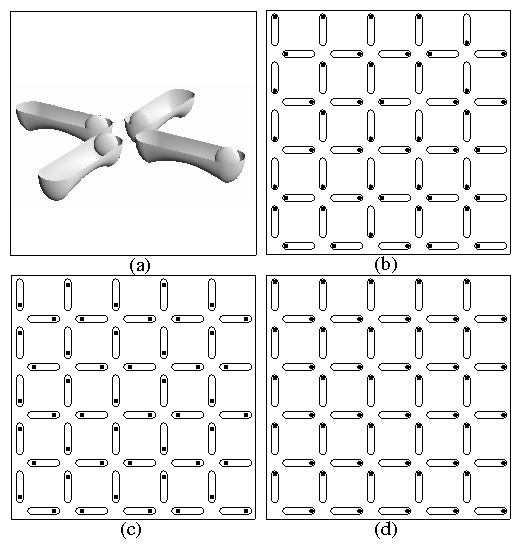
Figure 1: (a) Schematic of the basic unit cell with four double well traps each capturing one colloid. (b)-(d) Images of a small portion of system A with N=1800. Dark circles: colloids; ellipses: traps. (b) Random vertex distribution at q=0. (c) Long-range ordered square ice ground state at q=1.3. (d) Biased system at q=0.4 with Fdc=0.02.
Type Configuration Ei/EIII Type Configuration Ei/EIII
I 0000 0.001 IV 1001 7.02
II 0001 0.0214 V 1101 14.977
III 0101 1.0 IV 1111 29.913
Table 1: Electrostatic energy Ei/EIII for each vertex type. An example configuration for each vertex is listed; 1 (0) indicates a colloid close to (far from) the vertex.
The substrate force Fsi arises from elongated traps, shown schematically in Fig. 1(a), arranged in square structures with lattice constant d, as in Fig. 1(b). Each trap is composed of two half-parabolic wells of strength fp and radius rp separated by an elongated region of length 2l which confines the colloid perpendicular to the trap axis and has a small repulsive potential or barrier of strength fr parallel to the axis which pushes the colloid out of the middle of the trap into one of the ends: Fsik = (fp/rp)rik± Θ(rprik±)rik±+(fp/rp)rik Θ(rprik)rik+(fr/l)(1−rik||) Θ(lrik||)rik||. Here rik±=|rirkp ±lpk|||, rik⊥,|| = |(rirkp) ·pk⊥,|||, ri (rkp) is the position of colloid i (trap k), and pk|| (pk) is a unit vector parallel (perpendicular) to the axis of trap k. We take 2l=2a0, rp=0.4a0, and d=3a0 unless otherwise noted. Elongated traps of this form have been created in previous experimental work [11,12]. Our dimensionless units can be converted to physical units for a particular system. For example, when a0=2 μm, ϵ = 2, and Z*=300e, such as in Ref. [14], F0=2.5 pN and the trap ends are 0.2 μm apart at d=3. We find the ground state of each configuration using simulated annealing.
The vertices are categorized into six types, listed in Table I, and we identify the percentage occupancy Ni/N and energy Ei of each type. Type III and type IV vertices each obey the ice rule of a two-in two-out configuration, represented here by two colloids close to the vertex and two far from the vertex. Locally, the system would prefer type I vertices, but such vertices must be compensated by highly unfavorable type VI vertices. The colloidal spin ice realization differs from the magnetic system, where north-north and south-south magnetic interactions at a vertex have equal energy. For the colloids, interactions between two filled trap ends raise the vertex energy Ei, whereas two adjacent empty trap ends decrease Ei. Since particle number must be conserved, creating empty trap ends at one vertex increases the particle load at neighboring vertices. As a result, the ice rules still apply to our system, but they arise due to collective effects rather than from a local energy minimization.
In Fig. 1(b) we illustrate a small part of system A with noninteracting colloids at charge q=0. The distribution of Ni/N is consistent with a random arrangement. When we increase q to q=1.3 so that the colloids are strongly interacting, we find a nonrandom configuration where the system is filled with type III vertices in a checkerboard pattern corresponding to the square ice ground state [15], illustrated in Fig. 1(c). We find similar behavior in system B containing only 24 traps, which may be easier to realize in an experiment.
Fig2.png
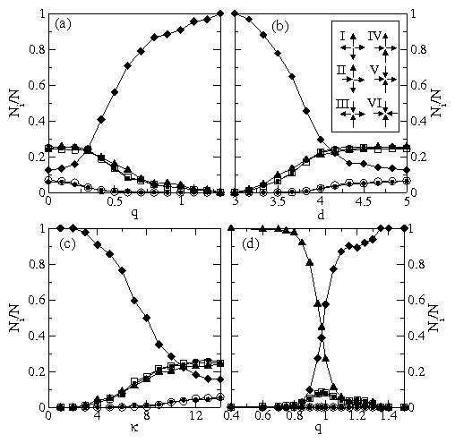
Figure 2: Ο: NI/N; : NII/N; : NIII/N; : NIV/N; : NV/N; •: NVI/N. (a) Ni/N vs q at d=3 and κ = 4.0. (b) Ni/N vs d at q=1.3 and κ = 4.0. Inset: schematic spin representation of the 6 vertex types. (c) Ni/N vs κ at d=3 and q=1.0. (d) Ni/N vs q for a biased system at d=3, κ = 4.0, and Fdc=0.02.
We use Ni/N to map the transition between the random state and the long-range ordered state as a function of colloid charge q at fixed trap spacing d=3 and κ = 4.0 in Fig. 2(a), as a function of d for fixed q=1.3 and κ = 4.0 in Fig. 2(b), and as a function of κ for fixed q=1.0 and d=3 in Fig. 2(c). Changing q, d or κ changes the relative colloid-colloid interaction strength. In Fig. 2(a), NI/N and NVI/N decrease with increasing q for q > 0.1, since this is the most energetically unfavorable vertex combination. As q increases above q > 0.3, NII/N, NV/N and NIV begin to decrease since type II, V and IV vertices are also energetically unfavorable. Even though type IV vertices obey ice rules, they disappear at high q since in square ice they have higher energy than the type III vertices, which ultimately form the ground state.
In Fig. 2(b) we fix q=1.3 and κ = 4.0 and show that changing the trap spacing d from d=3 to d=5 produces the same transition as changing the colloid charge. As d increases, the colloid-colloid interaction strength drops, and the vertices that were suppressed by the high colloid charge q reappear in the same order: types II, V and IV first, followed by types I and VI. If q and d are fixed and the inverse screening length κ is varied, we find that a similar transition from an ordered to a random configuration occurs, as illustrated in Fig. 2(c) for d=3 and q=1.0. In experiments with dynamic optical traps, it would be straightforward to adjust the trap spacing d, allowing both random and ordered limits to be accessed readily. The appearance of an ordered state for small trap spacing is similar to experimental observations of spin liquid ordering under pressure [16].
From these results we see that a colloidal system can serve as a model for artificial ice. The advantage of the colloid realization is that it is possible to directly observe the dynamical behavior of the individual "spins." It is also possible to create more complex systems than can be achieved with the magnetic system. For instance, to create biased traps, we introduce a small driving force oriented at a 45° angle along the diagonal of the square plaquettes. This causes the colloids to favor sitting in the topmost and rightmost halves of the traps, and breaks symmetry in the same way as applying a magnetic field along the [100] direction in a pyrochlore system [17,18,19,20]. In Fig. 1(d) we illustrate the ground state of a system biased in this way with q=0.4, d=3, κ = 4, and Fdc=0.02. All of the traps are effectively tilted in the rightward and upward directions, and the system has a ground state made up entirely of type IV vertices. In Fig. 2(d), we see that in the biased system, increasing q produces a transition between the tilted and the spin ice ground states. At the transition, we find vertex clusters composed entirely of type III or type IV vertices, with pairs of type II and type V vertices located at the boundaries between the clusters. Type I and type VI vertices never appear in this system.
Fig3.png
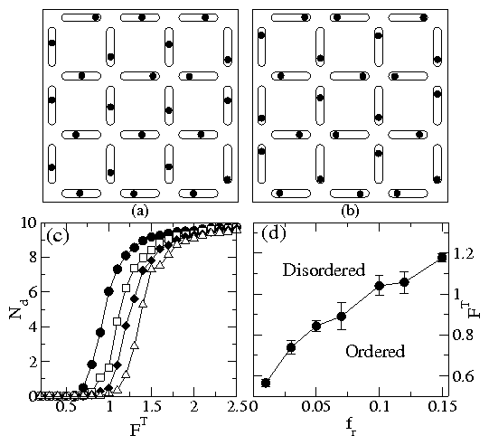
Figure 3: (a,b) Images of the entire sample for system B, with N=24 and open boundary conditions at d=3, q=1, κ = 4.0, and FT=0.9. (a) Disordered system at fr=0.01. (b) Square ice ground state at fr=0.10. (c) The number of defects Nd versus temperature FT for the same system with fr=0.03 (closed circles), fr=0.07 (open squares), fr=0.1 (closed diamonds), and fr=0.15 (open triangles). (d) A phase diagram showing the ordered and disordered states as a function of FT vs fr.
In experimental systems using current equipment, a limited number of optical traps are available. For example, 23 traps were employed in recent experiments on double well elongated traps [11]. It is therefore pertinent to determine how small of a system can still exhibit the artificial ice behavior. Additionally, experimental systems have no periodic boundary conditions, so it is important to understand whether the boundaries affect the response of the system.
In Fig. 3(a,b) we illustrate two configurations of system B, which contains 24 traps and has open boundary conditions, for the case q=1.0, d=3.0, and κ = 4.0 at a temperature FT=0.9. A disordered configuration, shown in Fig. 3(a), results when the strength of the repulsive barrier at the center of each trap, fr=0.01, is small. Here the thermal effects are strong enough that the colloids are hopping between the two different wells in each trap. As fr is increased, a freezing transition occurs and the system forms the ordered phase, seen in Fig. 3(b) for fr=0.10. To quantify the ordering transition, we measure the time-averaged number of defects in the system, Nd, which is determined by comparing the colloid configuration C with the two possible ground states for the 24 traps: G, shown in Fig. 3(b), and G′, obtained by flipping each colloid in Fig. 3(b) to the opposite side of each trap. We take Nd=〈min(∑iN|CiGi|,∑iN|CiGi|)〉, where |CiGi(′)|=0 (1) if colloid i is at the same (opposite) end of the trap in the two configurations. A plot of Nd versus FT in Fig. 3(c) shows that as FT is decreased, there is a freezing transition into the ordered state where Nd=0. The freezing temperature decreases as fr is lowered. The most straightforward experiment to perform would be to fix temperature and the other parameters while varying the strength of the barrier at the center of the traps, fr. To illustrate that the order-disorder artificial ice transition can also occur as function of barrier strength, we map out a phase diagram as a function of fr and FT in Fig. 3(d). This shows that for systems as small as 24 traps, the artificial ice behavior should be experimentally observable.
All of the systems we have studied up to this point have a well-defined, long-range ordered ground state. We have also found that if a honeycomb arrangement of traps is used instead of the square trap arrangement considered here, only disordered ground states occur [21].
In conclusion, we have shown that an artificial ice model system can be created using charged colloidal particles in arrays of elongated optical traps. The system obeys the ice rules and shows a transition between a random configuration and a long-range ordered ground state as a function of colloid charge, trap size, and screening length. We demonstrate that a thermally induced order-disorder transition also occurs in samples with only 24 traps and open boundary conditions, which should be well within the range of current experimental capabilities. This transition can be observed at fixed temperature by varying the trap barrier strength, which would be the most straightforward experiment to conduct. Besides optical traps, other systems including electrophoretic traps [22] or patterned surfaces may also be used to confine the colloids. Similar effects should occur for vortices in type II superconductors interacting with elongated arrays of blind holes. Experimental versions of frustrated colloidal systems could allow for direct visualization of the dynamics associated with frustrated spin systems, such as deconfined or confined spin arrangements, as well as spin dynamics at melting transitions.
This work was supported by the US Department of Energy under Contract No. W-7405-ENG-36.
Note added- Recently, a simulation study [23] of the experimental dipolar system appeared.

References

[1]
A.P. Ramirez, Annu. Rev. Mater. Sci. 24, 453 (1994).
[2]
M.J. Harris et al., Phys. Rev. Lett. 79, 2554 (1997).
[3]
S.T. Bramwell and J.M. Harris, J. Phys.: Condens. Matter 10, L215 (1998); S.T. Bramwell and M.J.P. Gingras, Science 294, 1495 (2001).
[4]
P.W. Anderson, Phys. Rev. 102, 1008 (1956); L. Pauling, The Nature of the Chemical Bond (Cornell University, Ithaca, NY, 1960) pp. 465.
[5]
R. Moessner and A.P. Ramirez, Phys. Today 59, No. 2, 24 (2006).
[6]
R.G. Melko, B.C. den Hertog, and M.J.P. Gingras, Phys. Rev. Lett. 87, 067203 (2001); R. Siddharthan, B.S. Shastry, and A.P. Ramirez, Phys. Rev. B 63, 184412 (2001).
[7]
R.F. Wang et al., Nature (London) 439, 303 (2006).
[8]
D.G. Grier, Nature (London) 424, 810 (2003).
[9]
P.T. Korda, G.C. Spalding and D.G. Grier, Phys. Rev. B 66, 024504 (2002); C. Reichhardt and C.J. Olson, Phys. Rev. Lett.  88, 248301 (2002); K. Mangold, P. Leiderer, and C. Bechinger, ibid. 90, 158302 (2003).
[10]
M. Brunner and C. Bechinger, Phys. Rev. Lett.  88, 248302 (2002).
[11]
D. Babic and C. Bechinger, Phys. Rev. Lett. 94, 148303 (2005); D. Babic, C. Schmitt and C. Bechinger, Chaos, 15, 026114 (2005).
[12]
C. Schmitt, B. Dybiec, P. Hanggi, and C. Bechinger, Europhys. Lett. 74, 937 (2006).
[13]
R. Youngblood, J.D. Axe, and B.M. McCoy, Phys. Rev. B 21, 5212 (1980).
[14]
M.F. Hsu, E.R. Dufresne, and D.A. Weitz, Langmuir 21, 4881 (2005).
[15]
F.H. Stillinger and K.S. Schweizer, J. Phys. Chem. 87, 4281 (1983).
[16]
I. Mirebeau et al., Nature (London) 420, 54 (2002).
[17]
M.J. Harris et al., Phys. Rev. Lett. 81, 4496 (1998).
[18]
A.P. Ramirez et al., Nature 399, 333 (1999).
[19]
H. Fukazawa et al., Phys. Rev. B 65, 054410 (2002).
[20]
Z. Hiroi et al., J. Phys. Soc. Japan 72, 411 (2003).
[21]
A. Libál, C. Reichhardt, and C.J. Olson Reichhardt, to be published.
[22]
A.E. Cohen, Phys. Rev. Lett. 94, 118102 (2005).
[23]
G. Möller and R. Moessner, Phys. Rev. Lett. 96, 237202 (2006).


File translated from TEX by TTHgold, version 4.00.

Back to Home