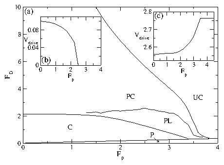
EPL 94, 18001 (2011)

The Effect of Pinning on Drag in Coupled One-Dimensional Channels of Particles

C. Bairnsfather1,2, C.J. Olson Reichhardt2 and C. Reichhardt2

1Theoretical Division, Los Alamos National Laboratory, Los Alamos, New Mexico 87545
2Department of Physics, Purdue University, West Lafayette, Indiana 47907

recieved 16 December 2010; accepted in final form 28 February 2011
published online 25 March 2011

PACS 82.70.Dd - Colloids
PACS 05.60.Cd - Classical transport
Abstract - We consider a simple model for examining the effects of quenched disorder on drag consisting of particles interacting via a Yukawa potential that are placed in two coupled one-dimensional channels. The particles in one channel are driven and experience a drag from the undriven particles in the second channel. In the absence of pinning, for a finite driving force there is no pinned phase; instead, there are two dynamical regimes of completely coupled or locked flow and partially coupled flow. When pinning is added to one or both channels, we find that a remarkably rich variety of dynamical phases and drag effects arise that can be clearly identified by features in the velocity force curves. The presence of quenched disorder in only the undriven channel can induce a pinned phase in both channels. Above the depinning transition, the drag on the driven particles decreases with increasing pinning strength, and for high enough pinning strength, the particles in the undriven channel reach a reentrant pinned phase which produces a complete decoupling of the channels. We map out the dynamic phase diagrams as a function of pinning strength and the density of pinning in each channel. Our results may be relevant for understanding drag coupling in 1D Wigner crystal phases, and the effects we observe could also be explored using colloids in coupled channels produced with optical arrays, vortices in nanostructured superconductors, or other layered systems where drag effects arise.
There are many examples of one- and two-dimensional (1D and 2D) coupled bilayers or coupled channels of interacting particles, including vortices in superconducting bilayers [1,2], colloidal systems [3,4,5,6], dusty plasmas [7], and Wigner crystals [8,9,10]. In many of these systems it is possible to apply an external drive to one of the layers and measure the resulting response of the other layer as well as the drag effect produced by the particles in the undriven layer on those in the driven layer. In two layer vortex systems a vortex decoupling transition occurs as a function of external drive [1,2]. A similar coupling-decoupling transition is also predicted for coupled wires containing 1D Wigner crystals [8], and certain drag effects in 1D wires have been interpreted as resulting from the formation of 1D Wigner crystal states [9].
Many of these systems can contain some form of quenched disorder which could produce pinning effects [11]; however, very little is known about how pinning alters the drag or transport properties in layered geometries. The quenched disorder could be strong in one channel and weak in another, or it could be of equal strength in both channels, resulting in different types of dynamic phases. Particles driven over random quenched disorder in single layer systems are known to exhibit a variety of dynamical phases associated with distinct transport signatures, as shown in simulations [11,12,13,14] and experiments [15]. These studies suggest that distinct dynamics could also arise in a two-layer drag system when pinning is present. We note that there have been studies of two-layer driven colloidal systems; however, the effect of quenched disorder was not considered [4].
In this work we propose a simple model of two coupled 1D channels of particles with repulsive Yukawa interactions where there is a drive channel and a drag channel, and where pinning is added to one or both channels. Despite the apparent simplicity of this system, we find that a remarkably rich variety of distinct dynamical phases are possible which produce pronounced changes in the transport and drag effects. Although our model treats 1D channels, we expect that many of the same effects should be generic to coupled layer systems with quenched disorder. The specific system we consider could be realized experimentally using colloidal particles in channel geometries [16] where a driving force is applied to one channel via optical means or an electric field. The effects we observe could also be studied with coupled 1D Wigner crystals [17,11,9,18] or in superconductors with nanofabricated channel geometries [19] when the current is applied to only one channel and the response is measured in both channels. In our system, we find that without pinning there is a finite drive transition from a locked regime to a partially decoupled regime in which the response of the drag channel decreases with increasing drive. Addition of pinning to the drag channel can induce a pinned phase for both channels. As the drive increases, both channels depin into a locked or partially locked phase, followed at high drives by a reentrant pinning of the drag channel when the dynamic coupling of the two channels becomes weak enough. When the driving force is fixed at a low value, increasing the strength of the pinning in the drag channel increases the effective drag on the particles in the driven channel; for higher fixed driving force, however, increasing the pinning strength reduces the drag on the driven channel and causes the channels to decouple when the drag channel becomes reentrantly pinned. We also observe strong fluctuations in both channels at the locked to partially locked transition for intermediate strengths of quenched disorder. We map out the evolution of the dynamical phases for a wide variety of parameters including pinning in both channels, pinning in only one of the channels, and for varied pinning densities.
Fig1.png
Figure 1: A schematic of the system of two coupled 1D channels separated by a distance d. Each channel contains N particles (black dots) which interact via a Yukawa potential with particles in the same and the adjacent channel. An external drive FD is applied to the particles in the drive channel, resulting in an average particle velocity of Vdrive in the drive channel. The velocity response in the drag channel is Vdrag. Quenched disorder is introduced in the form of localized pinning sites (open circles) of maximum force Fp which are spaced randomly in the channel without overlapping. The pinning can be placed only in the drag channel (as shown), only in the drive channel, or in both channels.
Simulation- In fig. 1 we show a schematic of our system which consists of two 1D channels separated by a distance d with periodic boundary conditions in the x-direction. Each channel contains N particles which interact via a repulsive Yukawa potential with other particles in the same channel and with particles in adjacent channels. Particles in the upper or drive channel are subjected to an applied external force FD. A single particle i located at position Ri undergoes motion obtained by integrating the overdamped equation of motion:
η dRi

dt
= Fipp + Fsi + FDi .
(1)
Here η is the damping constant which is set to η = 1.0. The particle-particle interaction force is Fppi = ∑2Nji−∇V(Rij)Rij where V(Rij) = (E0/Rij)exp(−κRij), Rij=|RiRj|, Rij=(RiRj)/Rij, and E0 = Z*2/4πϵϵ0. Here ϵ is the solvent dielectric constant and Z* is the effective charge. The unit of length a0, which is typically on the order of 0.6-3μm, is related to the average spacing a between particles in each channel as a=a0/2, and we take d/a=2/3. We take the screening length 1/κ = 4a/3=2d to ensure that coupling between the two channels is possible. We note that we have also considered other values of d, a, and κ and find the same qualitative features, indicating that our results should be generic for this class of system. The pinning force Fis arises from Np attractive parabolic potentials with a maximum force of Fp measured in units of E0/a0 and a radius of Rp=0.5, Fis=∑k=1NpFp(Rikp/Rp)Θ(RpRikp)Rikp. Here Θ is the Heaviside step function, Rkp is the location of pinning site k, Rikp=|RiRkp|, and Rikp=(RiRkp)/Rikp. In this work we consider the limit in which the number of pinning sites is smaller than or similar to the number of particles in the system; however, we find the same qualitative features when we change the pinning density or strength. To prevent double occupancy of the pinning sites, we take Rp=1/8κ. The external force FD is applied only to the particles in the driven channel. We increase FD from zero in small increments of δFD = 0.001, spending a waiting time of 104 simulation time steps at each increment. We measure the average velocity of the particles in the drive and drag channels, Vdrag=Ndrag−1i=1NdragdRi/dt and Vdrive=Ndrive−1i=1NdrivedRi/dt, where Ndrag=N is the number of particles in the drag channel and Ndrive=N is the number of particles in the drive channel. For most of the results we take N = 48; however, the same generic phases appear for systems with the same particle density for N as low as 12 as well as for higher N. This simulation method, employing overdamped dynamics with random pinning, has been used previously to explore the behavior of colloids driven over random and periodic substrates as well as two layer systems. A similar method has been used to study sliding Wigner crystals and vortices in type-II superconductors.
Fig2.png
Figure 2: (a-d) The average particle velocity in the drive channel Vdrive and the drag channel Vdrag vs applied force FD for a sample with pinning in the drag channel at Np/N=0.083. (a) The pin-free case Fp = 0.0 has two regions: an initial coupled region (C) where motion in both channels is completely locked, and a partially coupled (PC) region where Vdrag monotonically decreases while Vdrive increases with increasing FD. (b) For Fp = 1.0 there is an initial pinned region (P) in both channels in addition to the C and PC regions. (c) At Fp = 2.5, a pulse locked (PL) region containing a series of asymmetric jumps in Vdrag appears between the C and the PC regions. At FD=5.66 there is a reentrant pinning of the drag channel above which Vdrag = 0.0, producing an uncoupled region (UC). (d) At Fp = 4.0, only the P and UC regions appear and Vdrag=0 for all FD. (e) Light line: a blowup of Vdrag from panel (c) centered on the PL region. Dark line: Vdrag from a sample with a different random arrangement of pinning sites shows that the jump features appear at nearly fixed values of FD for FD < 2. (f) Vdrag at fixed FD vs time in simulation time steps. Light line: a periodic signal in the Fp=0 system from panel (a) at FD = 2.5. Dark line: the Fp=2.5 system from panel (c) in the PL region at FD = 1.6 is still periodic but has a much longer period.
In fig. 2(a) we show the velocity force curves Vdrive and Vdrag versus FD for the case where there is no pinning in either channel. At low FD, Vdrive=Vdrag, indicating that the particles are moving together in the coupled (C) region. At FD = 2.0, the average particle velocity in each channel is Vdrive=Vdrag=1.0. Under our overdamped dynamics, V=NdriveFD/(Ndrive+Ndrag)η. If there were no drag channel, then we would have V=FD/η, giving Vdrive=2.0 for FD=2.0. In the presence of the drag channel, twice as many particles must be transported by the same driving force, so the velocity is cut in half. At FD = 2.124 there is a transition to a partially coupled (PC) state where the velocity curves branch apart. Vdrive continues to increase with increasing FD with a slope higher than the slope of Vdrive below FD=2.124, while Vdrag decreases with increasing FD. Since there is no pinning, in the PC region Vdrag gets smaller and smaller with increasing FD but never reaches zero. The general shape of the velocity force curves is very similar to the response observed for the superconducting transformer geometry where vortices in a pair of adjacent superconducting layers can couple and decouple depending on the applied current [1,2]. In the superconducting system, the voltage response is proportional to the particle velocity and the applied current is proportional to FD. Additionally, the velocity-force curves in fig. 2(a) are in agreement with the predicted coupling-decoupling transition for disorder-free coupled 1D Wigner crystal systems [8].
In fig. 2(b) we plot Vdrive and Vdrag versus FD for a system containing pinning in the drag channel with Np/N=0.083 and Fp=1.0. The curves are similar to the pin free case, but a pinned region (P) now appears for FD < 0.1 when the quenched disorder in the drag channel causes the particles in both channels to stop moving. The particles in the drag channel are directly pinned by the pinning sites, but the particles in the driven channel are only indirectly pinned by their interactions with the particles in the drag channel, which produce an effective periodic pinning potential for the driven particles. The driven particles can either simply move over this periodic potential, in which case we find a decoupled region (UC) where the driven particles are moving and the drag particles are pinned, or the driven particles can drag the periodic potential along with them, depinning the drag particles and producing a moving coupled region. As FD increases, there is a transition from the coupled to partially coupled flow at the same FD=2.124 as in the pin-free system.
Figure 2(c) shows the velocity-force curves for a sample with Fp = 2.5, where the transition out of region C falls at a lower FD = 1.26 and is followed by a region containing a series of jumps in both Vdrive and Vdrag. In this pulse locked (PL) region, a group of the drag particles are locked with the drive particles while the remaining drag particles are unlocked. The locked group moves as a pulse through the drag channel by picking up unlocked particles on its leading edge and losing locked particles on its trailing edge. As FD increases, Vdrag increases with a slope that is determined by the number of particles in the locked group, since the velocity of the locked particles increases with increasing FD. When Vdrag ≈ 0.6, the locked group becomes unstable and suddenly decreases in size, producing a large drop in Vdrag. The velocity of the particles in the new, smaller locked group increases with increasing FD, but the slope of Vdrag is reduced due to the smaller number of locked particles. As FD increases, the locked group continues to decrease in size until it becomes poorly defined and the system crosses over to the partially coupled (PC) region where Vdrag decreases linearly and smoothly with increasing FD. For FD < 2, jumps in Vdrag in the PL phase occur at well-defined values of FD, as illustrated in fig. 2(e) for two different disorder realizations; the quenched disorder only affects the locations of the jumps after the size of the locked group becomes small.
At high FD in fig. 2(c), the uncoupled channel (UC) region appears when the particles in the drag channel become pinned again for FD ≥ 5.66 but the particles in the driven channel continue to flow. The reentrant pinning of the drag channel results when the effective dynamical coupling between the two channels weakens for higher FD, as indicated by the decrease in Vdrag with increasing FD in the PC region of the pin-free sample shown in fig. 2(a). When the dynamical coupling between the channels drops below a critical value, the drag force experienced by the particles in the drag channel falls below the depinning threshold for the pinning sites in the drag channel, resulting in the repinning transition. We expect this reentrant pinning effect to be a generic feature in drag systems containing quenched disorder, and its signature is a sudden decrease of Vdrag to zero. In fig. 2(d) for Fp = 4.0, the drag channel never depins over the range of FD shown, and there is a single transition from region P where both channels are pinned to the decoupled region UC.
Each dynamic phase exhibits distinct velocity fluctuations. In the absence of pinning, no fluctuations occur in the C region but a periodic velocity signal appears in the UC regime, as illustrated in fig. 2(f). This periodic signal arises when the particles in the two layers which are sliding past one another arrange themselves in a periodic spacing. In the presence of pinning, a periodic signal appears in the C phase due to the slowing of the particles as they pass repeatedly over the pinning sites. In the PL region, the velocity response remains periodic but the length of the period can increase substantially, as illustrated in fig. 2(f) for a sample with Fp=2.5 at FD = 1.6. In all the cases we have examined, we find only periodic signals rather than chaotic or nonstationary velocities. Chaotic signals may occur in the presence of finite temperature or if additional randomness is added to the pinning sites such as by introducing random radii or random pinning strengths. Additionally, if the channel fillings are incommensurate with each other (Ndrag/Ndrive ≠ 1), additional dynamical behaviors could arise.
Fig3.png
Figure 3: (a) The dynamic phase diagram of FD vs Fp for the system in fig. 2 for pinning in only the drag channel. Each region is marked: pinned (P), coupled (C), pulse locked (PL), partially coupled (PC), and uncoupled (UC). (b) Vdrive versus Fp from the system in (a) at FD = 0.2. The increasing effective damping η*=FD/Vdrive produces a monotonic decrease in Vdrive with increasing Fp until the particles in the driven channel repin and the velocity drops to zero in region P. (c) Vdrive vs Fp for the system in (a) at FD = 3.0. Here Vdrive increases with increasing Fp until the onset of the UC phase, above which Vdrive saturates to a constant value.
In fig. 3(a) we plot the dynamic phase diagram FD versus Fp for the system in fig. 2 containing pinning only in the drag channel. The transition between the PC and UC regions drops to lower values of FD with increasing Fp since a lower drive is required to reduce the effective drag force below the depinning threshold of the drag channel at higher Fp. For Fp > 3.88, only the P and UC regions appear. The extent of region C decreases with increasing Fp until region C disappears for Fp > 3.45. The PL region vanishes at higher values of FD and reaches its maximum extent near Fp = 2.95. In fig. 3(b) we plot Vdrive versus Fp for the same system at fixed FD=0.2. Here Vdrive decreases with increasing FP until the system enters the pinned region at Fp = 2.0 and Vdrive drops to zero. The effective damping of the driven particles, η* = FD/Vdrive, increases with increasing Fp. In fig. 3(c) we show Vdrive versus Fp at fixed FD = 3.0, where Vdrive monotonically increases until the system enters the UC phase, and Vdrive saturates to a constant value. These results show that pinning in the drag channel can either increase or decrease the effective drag on the driven channel depending on the strength of the pinning and the amplitude of the dc drive.
Fig4.png
Figure 4: (a) The dynamic phase diagram of FD vs Fp for a system with pinning in both channels with Np/N=0.083. The region labels are the same as in fig. 3(a). (b) The dynamic phase diagram of FD vs Fp for a system with pinning in only the drive channel, with Np/N = 1.33. Here the UC region is absent and there can be a direct transition from region P to region PC. (c) Vdrive (upper curve) and Vdrag (lower curve) vs FD for the system in (a) at Fp = 4.0. Inset: Vdrive vs Fp for the system in (a) at FD=3.0. (d) Vdrive (upper curve) and Vdrag (lower curve) vs FD for the system in (b) at Fp = 7.5. Inset: Vdrive vs Fp for the system in (b) at FD = 3.0.
We next consider a system containing pinning in both channels. Figure 4(a) shows the dynamic phase diagram of FD versus Fp for a sample with a pinning density of Np/N=0.083 in each channel. The overall shape of the phase diagram resembles the phase diagram in fig. 3(a) obtained with pinning in only the drag channel. The pinned phase P grows in size with increasing Fp much more rapidly when there is pinning in both channels than when there is pinning in only the drag channel. In fig. 4(c) we plot Vdrive and Vdrag versus FD at Fp=4.0 for the sample from fig. 4(a) with pinning in both channels. When Vdrag drops to zero at FD=2.22 at the transition to region UC, there is a jump up in the value of Vdrive. In fig. 4(b) we show the phase diagram of FD versus FP for a sample containing pinning in only the drive channel with Np/N = 1.33. The UC phase no longer appears since the particles in the drag channel can only reentrantly repin when there is pinning in the drag channel. For Fp > 5.5, the system crosses directly from region P to region PC without passing through the C region. Figure 4(d) illustrates Vdrive and Vdrag versus FD for this system at Fp=7.5. There is a transition directly from region P to region PC at FD=4.8, and above this drive Vdrag gradually decreases with increasing FD.
In the inset of fig. 4(c) we plot Vdrive versus Fp at FD = 3.0 for the system in fig. 4(a) where there is pinning in both channels. For Fp < 3.5, Vdrive increases with increasing Fp, just as shown in fig. 3(c) for the sample with pinning in only the drag channel. For Fp > 3.5, when there is pinning in both channels Vdrive decreases with increasing Fp for Fp > 3.5 rather than saturating. The increase in Vdrive with increasing Fp for Fp < 3.5 results when the pinning in the drag channel reduces the coupling between the driven and drag particles. For Fp > 3.5 at FD = 3.0, the particles in the drag channel are always pinned. If there is pinning in only the drag channel, Vdrive remains constant for Fp > 3.5 as shown in fig. 3(c); however, if pinning is also present in the drive channel, it produces an increasing drag on the driven particles, causing Vdrive to decrease with increasing Fp at Fp > 3.5 for the sample with pinning in both channels. In the inset of fig. 4(d) we illustrate this effect more clearly by plotting Vdrive vs Fp for a system with pinning in only the drive channel. Here Vdrive monotonically decreases with increasing Fp until it reaches zero once all the drive particles become pinned.
Fig5.png
Figure 5: (a) The dynamic phase diagram of FD vs d/a for a sample with pinning in both channels at Fp = 2.0 and with Np/N = 0.25 at d/a = 0.67. (b) The dynamic phase diagram of FD vs Np/N for a sample with pinning in only the drag channel at d/a = 0.67 and Fp = 1.0.
We vary d/a, where a ∝ 1/N is the average particle spacing within the channels, by fixing d and the system size while increasing both N and Np to keep Np/N constant while changing a. Increasing the particle density reduces the effective coupling between the channels since the periodic potential experienced by the particles in one channel produced by the particles in the other channel becomes smoother as the particle density increases. In fig. 5(a) we plot the dynamic phase diagram for Fd versus d/a in a sample with pinning in both channels for fixed Fp = 2.0 and with Np/N = 0.25 at d/a = 0.67. At low d/a, there is a large pinned region since the particles within each channel are far from each other, strongly enhancing the effectiveness of an individual pinning site. For d/a < 0.22, the system passes directly from region P to region UC. For large d/a, each particle interacts strongly with other particles in the same channel but the coupling to particles in the other channel is greatly reduced, so the system again crosses directly from the pinned to the UC region. For intermediate values of d/a, the three other regions C, PL, and PC appear in windows between the P and UC regions. The total width of these intermediate windows reaches a peak at d/a=0.66. In fig. 5(b) we show the dynamic phase diagram of FD versus the pinning density Np/N for a system with pinning in only the drag channel at Fp = 1.0 and d/a = 0.67. The transition from region PC to region UC drops to lower FD with increasing Np/N since higher pinning density causes the repinning threshold in the drag channel to decrease. The transition between region C and region PC also shifts to lower FD with increasing Np/N, and there is a narrow window (not labeled on the figure) where region PL appears between regions C and PC. There is also a small plateau in all of the transitions near Np/N = 1.0, which is a weak commensuration effect. For periodically arranged pinning sites, we expect much stronger commensuration effects to occur; these effects will be considered elsewhere.
In summary, we introduce a simple model to study the effects of pinning on drag in coupled 1D channels of particles interacting via a Yukawa potential where a drive is applied to only one channel. This system exhibits a rich variety of dynamical phases which produce distinct features in the velocity-force curves. In the absence of pinning, at low drives both channels are coupled and exhibit identical particle velocities. As the drive is increased, there is a transition to a partially coupled phase where the velocity in the drag channel deceases with increasing drive while the velocity in the driven channel increases with increasing drive. Placing pinning in only the drag channel produces a region in which both channels are pinned as well as a reentrant pinning of the particles in the drag channel at higher drives when the coupling between the channels is dynamically weakened. When strong pinning is placed either in the drag channel or in both channels, we observe only a pinned region and a decoupled region. For intermediate pinning strength, we find a pulse locked region where a series of asymmetric jumps appear in the velocity-force curves. Increasing the strength of the pinning in the drag channel generally reduces the effective drag on the particles in the driven channel at higher drives since the pinned particles in the drag channel are unable to absorb momentum from the particles in the drive channel. We map the dynamic phase diagrams for samples with pinning in both channels, in only the drive channel, and in only the drag channel. The smallest number of phases appears for pinning in only the drive channel, while samples with pinning in both channels exhibit multiple dynamical phase transitions even when the particle density or pinning density is altered, showing that the effects we observe are robust for a wide range of parameters. Our results could be important for understanding drag effects in systems where 1D Wigner crystal states can occur and for understanding the general effects of quenched disorder in other drag and transformer geometries. Additionally, our system could be directly realized experimentally for colloidal or dusty plasma systems in coupled 1D channels. Extensions of this model that could be explored include the effects of a periodic pinning array at and away from commensurability, as well as the effects of disorder on the coupling of particles confined in adjacent 2D planes.
This work was carried out under the auspices of the NNSA of the U.S. DoE at LANL under Contract No. DE-AC52-06NA25396.

References

[1]
Giaever I. Phys. Rev. Lett. 15 (1965) 825.
[2]
Clem J.R. Phys. Rev. B 9 (1974) 898; Ekin J.W., Serin B. and Clem J.R. Phys. Rev. B 9 (1974) 912.
[3]
Messina R. and Löwen H. Phys. Rev. Lett. 91 (2006) 146101.
[4]
Das M., Ananthakrishna G. and Ramaswamy S. Phys. Rev. E 68 (2003) 061402; Messina R. and Löwen H. Phys. Rev. E 73 (2006) 011405.
[5]
Lutz C., Kollmann M. and Bechinger C. Phys. Rev. Lett. 93 (2004) 026001.
[6]
Herrera-Velarde S., Zamudio-Ojeda A. and Castañeda-Priego R. J. Chem. Phys. 133 (2010) 114902; Coste C., Delfau J.-B., Even C. and Saint Jean M. Phys. Rev. E 81 (2010) 051201.
[7]
Hartmann P., Donkó Z., Kalman G.J., Kyrkos S., Golden K.I. and Rosenberg M. Phys. Rev. Lett. 103 (2009) 245002.
[8]
Baker J.and Rojo A.G. J. Phys.: Condens. Matter 13 (2001) 5313.
[9]
Yamamoto M., Stopa M., Tokura Y., Hirayama Y. and Tarucha S. Science 313 (2006) 204.
[10]
Goldoni G. and Peeters F.M. Phys. Rev. B 53 (1996) 4591.
[11]
Piacente G. and Peeters F.M. Phys. Rev. B 72 (2005) 205208.
[12]
Koshelev A.E. and Vinokur V.M. Phys. Rev. Lett. 73 (1994) 3580; Faleski M.C., Marchetti M.C. and Middleton A.A. Phys. Rev. B 54 (1996) 12427; Olson C.J., Reichhardt C. and Nori F. Phys. Rev. Lett. 81 (1998) 3757; Kolton A.B., Domínguez D. and Grønbech-Jensen N. Phys. Rev. Lett. 83 (1999) 3061; Fily Y., Olive E., Di Scala N. and Soret J.C. Phys. Rev. B 82 (2010) 134519.
[13]
Reichhardt C. and Olson C.J. Phys. Rev. Lett. 89 (2002) 078301; Chen J.X., Cao Y. and Jiao Z. Phys. Rev. E 69 (2004) 041403; Reichhardt C. and Olson Reichhardt C.J. Phys. Rev. E 79 (2009) 061403; Sengupta A., Sengupta S. and Menon G.I. Phys. Rev. B 81 (2010) 144521.
[14]
Reichhardt C. and Olson Reichhardt C.J. Phys. Rev. Lett. 93 (2004) 176405.
[15]
Bhattacharya S. and Higgins M.J. Phys. Rev. Lett. 70 (1993) 2617; Pardo F., de la Cruz F., Gammel P.L., Bucher E. and Bishop D.J. Nature 396 (1998) 348; Pertsinidis A. and Ling X.S. Phys. Rev. Lett. 100 (2008) 028303; Guiterrez J., Silhanek A.V., Van de Vondel J., Gillijns W. and Moshchalkov V.V. Phys. Rev. B 80 (2009) 140514(R); Avci S., Xiao Z.L., Hua J., Imre A., Divan R., Pearson J., Welp U., Kwok W.K. and Crabtree G.W. Appl. Phys. Lett. 97 (2010) 042511.
[16]
Köppl M., Henseler P., Erbe A., Nielaba P. and Leiderer P. Phys. Rev. Lett. 97 (2006) 208302; Bleil S., Reimann P. and Bechinger C. Phys. Rev. E 75 (2007) 031117.
[17]
Piacente G., Schweigert I.V., Betouras J.J. and Peeters F.M. Phys. Rev. B 69 (2004) 045324; Piacente G., Hai G.Q. and Peeters F.M. Phys. Rev. B 81 (2010) 024108.
[18]
Deshpande V.V. and Bockrath M. Nature Phys. 4 (2008) 314.
[19]
Besseling R., Kes P.H., Dröse T. and Vinokur V.M. New J. Phys. 7 (2005) 71; Yu K., Heitmann T.W., Song C., DeFeo M.P., Plourde B.L.T., Hesselberth M.B.S. and Kes P.H. Phys. Rev. B 76 (2007) 220507(R).


File translated from TEX by TTHgold, version 4.00.

Back to Home