MRS Advances 4, 643 (2019)

Skyrmions in anisotropic magnetic fields: strain and defect driven dynamics

Richard Brearton1,2, Maciej W. Olszewski3, Shilei Zhang1, Morten R. Eskildsen3, Charles Reichhardt4, Cynthia J. O. Reichhardt4, Gerrit van der Laan2, Thorsten Hesjedal1

1University of Oxford, Clarendon Laboratory, Parks Road, Oxford OX1 3PU, England
2Magnetic Spectroscopy Group, Diamond Light Source, Fermi Ave, Didcot OX11 ODE, England
3Department of Physics, Universty of Notre Dame, Notre Dame, IN 46656, U. S. A. 4Theoretical Division, Los Alamos National Laboratory, Los Alamos, NM 87545, U. S. A.

ABSTRACT
Magnetic skyrmions are particle-like, topologically protected magnetization entities that are promising candidates for information carriers in racetrack-memory schemes. The transport of skyrmions in a shift-register-like fashion is crucial for their embodiment in practical devices. Recently, we demonstrated experimentally that chiral skyrmions in Cu2OSeO3 can be effectively manipulated by a magnetic field gradient, leading to a collective rotation of the skyrmion lattice with well-defined dynamics in a radial field gradient. Here, we employ a skyrmion particle model to numerically study the effects of resultant shear forces on the structure of the skyrmion lattice. We demonstrate that anisotropic peak broadening in experimentally observed diffraction patterns can be attributed to extended linear regions in the magnetic field profile. We show that topological (5-7) defects emerge to protect the six-fold symmetry of the lattice under the application of local shear forces, further enhancing the stability of proposed magnetic field driven devices.
INTRODUCTION
SIMULATION
RESULTS
Lattice strain
Defect dynamics
CONCLUSIONS
REFERENCES

  INTRODUCTION

The encoding of magnetic bits via topologically protected spin configurations presents an interesting route for scaling down magnetic random-access memory, as the scaled magnetic bits remain inherently robust against superparamagnetism [1]. In chiral magnets, individual skyrmion spin swirls assemble into hexagonally closed-packed lattices. Examples of chiral magnets in which skyrmion lattices have been found are MnSi [2], Fe0.5Co0.5Si [3], FeGe [4], Cu2OSeO3 [5], and CoxZnyMnz [6]. The magnetic skyrmion lattice in these materials is in general incommensurate with the atomic lattice. The magnetic skyrmion lattice is highly mobile and can be manipulated via spin-transfer torque (STT) using very low current densities [7,8,9,10]. A recognized use of such skyrmion systems is racetrack memory, which shows great promise for future memory applications [1,11,12].
Recently, we have demonstrated that skyrmions can be manipulated in a controlled manner with the aid of a magnetic field gradient [13]. First, in a practical skyrmion racetrack device, Oersted fields can be used to create a similar field gradient. Although Joule heating is in principle inevitably generated in the coils, the required current densities are orders of magnitude smaller compared with those needed for direct, STT- driven skyrmion transport in metallic systems. Our scheme also avoids local heating of the skyrmion-hosting material and can be applied to all skyrmion materials regardless of their electronic properties, i.e., including insulating materials. Second, the direction of the moving skyrmions and their velocity can be directly controlled via the field gradient parameters. It is worth noting that in our experiment, the observed angular velocity is rather slow (i.e., less than 1° s −1 ), as the observed skyrmion lattice domain tracks extend to a rather large radius on the mm scale. Nevertheless, the angular velocity is much faster for very small domains as they appear close to the centre of the field distribution, or in patterned nano-sized disks. Moreover, in our experiment, the small applied gradient of less than 0.1 mT mm−1 was sufficient to control the skyrmion motion. The magnitude of the gradient can easily be increased and will thus proportionally enhance the rotational speed, potentially bringing it up to device-compatible values.
Despite these crucial insights into the rotational dynamics of skyrmion lattice, a number of important observations have remained unexplained [13]. Here, we use molecular dynamics simulations of the skyrmion lattice to study the effect of the dynamics of field- driven motion on the lattice order, and especially the role of lattice defects.

  SIMULATION

figure1.png
Figure 1: Experimental scattering data obtained from a skyrmion lattice taken at different times during the rotation in a radial magnetic field gradient. The resonant elastic x-ray scattering (REXS) data were obtained in the skyrmion lattice phase, characterized by spots, at a temperature of 57 K and in a bias field of 25 mT. (a) The hexagonally symmetric diffraction peaks appear to be stretched and slightly rotated with respect to the qy-axis. (b) Small additional peaks appear in the diffraction pattern, which move irregularly and quickly compared to the larger peaks. (c) The small domains which gave rise to the additional peaks in (b), have been reabsorbed into the larger domain.
In our original experiment, the x-ray beam illuminated  ∼ 20,000 μm2 of the Cu2OSeO3 surface, effectively leading to scattering from a macroscopic skyrmion system (note that the skyrmion lattice constant in Cu2OSeO3 is  ∼ 70 nm). A time series of representative images of the observed diffracted intensity is shown in figure 1. The dynamics of a skyrmion are governed by its winding number N = [1/(4π)]∫∫[(∂m)/(∂y)] ×[(∂m)/(∂x)] ·m  dx  dy, where m is the magnetization unit vector and the integral is over the projection of a skyrmion onto a 2D plane. Using the approach pioneered by Thiele, one can write an approximate equation of motion describing the time evolution of a skyrmion’s center of mass as [14]:

G
 
×

v
 
Dα

v
 
= ∇E  .
(1)
In the first term, G = (0,0,−4πNMs) is the gyromagnetic coupling vector and is finite only for integer N; Ms is the saturation magnetization [8]. This term gives rise to the skyrmion Hall effect, as a driving force ∇E causes the skyrmion to move at an angle θSkH = tan−1 ([(|G|)/(Dα)]) from the direction of the applied force. The components of the dissipative tensor D and the damping coefficient α are typically small in skyrmion hosting materials, so that θSkH often approaches 90° [15]; in such scenarios, skyrmions are driven along contours of constant energy, which in the case of our experiment corresponds to contours of constant magnetic field.
In this experiment, the skyrmions were subject to a non-uniform magnetic field of the form Br(r,θ)=B0B2 r2f(r,θ); terms of the form B1 r are unphysical as they give rise to a magnetic field which is not smooth at the origin. In a system with f(r,θ) = 0, we have ∇EB ∝ −B2 r; setting θSkH to be 90° then vskr θ so that the angular velocity ω does not depend on r. This implies that the skyrmion lattice should rotate in phase, which must not be the case as the diffraction pattern often deviates from being perfectly hexagonal and figure 1(b) explicitly shows domain rotation with varying ω. Here we simulate regions in which contours of constant magnetic field in the xy-plane locally have no curvature and lead to a force profile of the form FB(x) = −2B2 x y. Regions such as these arise if one breaks continuous azimuthal symmetry by allowing f(r,θ) ≠ 0. If azimuthal symmetry is N-fold then terms such as f(r,θ)=r2 cos2 (Nθ+ ϕ) are allowed in the Taylor expansion of the B-field about the origin, where ϕ is just a phase factor [16]. This gives rise to a magnetic field of the form B(r,θ) = B0r2(B2 + kani cos2(Nθ)), where kani dictates the magnitude of the anisotropy. The energy due to the coupling of a skyrmion to the magnetic field EB(x,y) is linear in B, which is plotted in figures 2(a) and 2(b).
figure2.png
Figure 2: Real space images of an anisotropic magnetic field B. (a) An image of how a 4-fold symmetric magnetic field would look in a region the same size as the x-ray beam. The small red square represents the size of the simulation compared to the size of the sample, dotted lines denote contours of constant B. (b) A zoomed-in image of the red region in (a), clearly well described by FB(x) = − 2B2 xy .
It has recently been shown that the skyrmion-skyrmion interaction potential Fijsksk can be well modeled analytically [17], so that the ith skyrmion trajectory can be described by G ×viDαvi = ∑ij Fijsksk+ 2 B2 x y. Here we integrate this effective equation of motion using the second order Runge-Kutta method in a system containing 5138 skyrmions, subject to periodic boundary conditions. The skyrmion hall angle θSkH is taken to be 85° to account for finite damping and dissipation effects and to allow the system to relax to lower energy states. To ensure continuity of FB(x) = −2B2 xy, we simulate a system which is symmetric about x=0 and use FB(|x|), so that FB(−|xmax|) = FB(|xmax|).

  RESULTS

  Lattice strain

We have performed simulations of the dynamics of a skyrmion lattice in the presence of the shear force FB(x) = −2B2 x y for a range of values of B2, requiring that FB << Fijsksk. The primary effect of this shear force is to rotate and strain the skyrmion lattice parameters not parallel to the [010] direction. Typical perturbations to [100] lattice parameters are shown by the dotted line in figure 3(a). This strain gives rise to asymmetric peak broadening in the structure factor as shown in figure 3(b), which is clearly observed in experiments (see e.g. figure 1(a)). As the system evolves further through time, strain builds up and the lattice becomes increasingly distorted as captured in figures 3(c) and 3(d). Despite the significant impact that this distortion has on this [100] lattice parameter in the system, the lattice retains mostly its hexagonal symmetry and skyrmions can still clearly be seen to lie in vertically well-ordered columns.
figure3.png
Figure 3: Results of molecular dynamics simulations of a skyrmion lattice under the influence of a driving force parallel to the y-axis Fy ∝ −x. (a) Triangular primitive lattice vectors are shown in blue, the dotted line represents the typical deviation of the [100] vector from its unstrained value. Edges of Voronoi cells surrounding each lattice point are drawn as dark lines to guide the eye. (b) The modulus of the structure factor of a typical strained system, including only first-order peaks, rotated by 90° for comparison with figure 1. (c) The real space configuration of the lattice whose structure factor is shown in (b). Skyrmions are denoted by black arrows which indicate their relative velocities. Voronoi cells surrounding each skyrmion are colored according to the magnitude of the local [100] lattice parameter, the edges of each Voronoi cell are drawn in with dark lines. (d) The same simulation and region as in (a), evolved further in time and subject to a larger shear force. Qualitatively the system is identical, but the standard deviation of [100] lattice parameters from the mean length has increased.
Regardless of the initial configuration of the skyrmion lattice, the mirror symmetry of FB forces the lattice to immediately anneal into columns of skyrmions parallel to the y-axis. This symmetry also appears to protect the structure factor peaks lying on the qy-axis - while strain develops in the lattice no (010) peak broadening is observed. In the experimental system there is no perfect mirror symmetry about the direction of motion and all diffraction peaks are found to be stretched.

  Defect dynamics

Adjacent columns of skyrmions move at different speeds; inevitably large numbers of skyrmions must move past each other. The mechanism by which this occurs involves the nucleation of a topological 5-7 defect in the system, allowing skyrmions to slip past each other sequentially. This process is shown in figure 4(a). In the immediate vicinity of the defect the [010] lattice parameter is stretched in one column and contracted in the other, ensuring that only a single pair of skyrmions deviate from having 6 nearest neighbors in any column of skyrmions. As the [010] lattice parameter only changes in the vicinity of defects, there is no visible broadening of the (010) peak in the structure factor shown in figure 4(b) - instead there is very clear peak splitting and broadening along the (100) direction. This can be attributed to the fact that 5-7 defects drive domain boundaries between regions with extended and contracted [100] lattice parameters, which can be seen by inspecting figures 4(c) and 4(d).
figure4.png
Figure 4: Images depicting the motion of 5-7 defects in molecular dynamics simulations of a skyrmion lattice under a driving force parallel to the y-axis, Fy ∝ −x. 
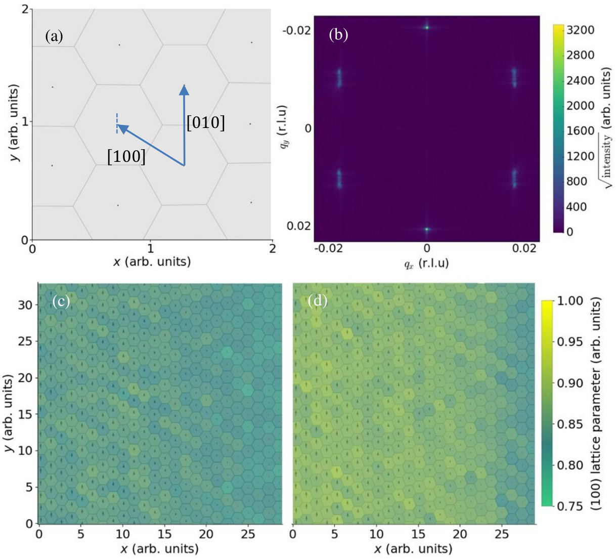
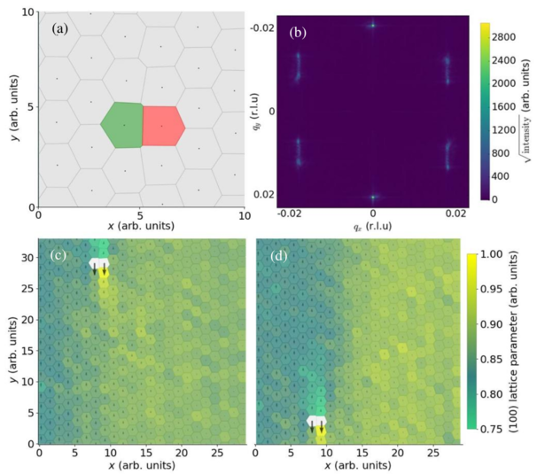
(a) A frame containing a single 5-7 defect. The green Voronoi cell (left) contains a skyrmion with 7 nearest neighbors while the red cell (right) has only 5. (b) The modulus of the structure factor of a system containing a 5-7 defect, rotated by 90° for comparison with figure 1. The observed peak splitting in reciprocal space reflects the fact that defects drive the domain boundary between extended and contracted lattice parameter domains in real space. (c) An image of a skyrmion system under shear force, where arrows depict the relative motion of each skyrmion/defect. If a skyrmion has 6 nearest neighbors, the color of its Voronoi cell denotes the magnitude of the local [100] lattice parameter and the edges of each Voronoi cell are drawn in with dark lines; 5-7 defects are colored in white. (d) As in (c), but the system has been evolved further in time. Here the 5-7 defect is travelling by gliding antiparallel to the motion of the skyrmion lattice with far greater speed, driving the boundary between extended and contracted lattice parameter domains.
We also found that 5-7 defects are effectively decoupled from the underlying skyrmion lattice, moving parallel or antiparallel to the direction of applied force. For an entire column of skyrmions to move past another, the defect must travel through each skyrmion by gliding like a zip between the columns. This yields a lifetime for each defect, which is governed by the difference between skyrmion speeds in adjacent columns, which in the limit FB << Fijsksk is typically small. As such, defects behave as quasiparticle excitations with lifetimes comparable to the time required for a skyrmion to traverse the length of the simulation geometry, which is around 2 μm (see figure 2). In our experimental system ω ≈ 1° s−1, meaning that defects arouns 100 μm from r=0 could have lifetimes of  ∼ 1 s.

  CONCLUSIONS

We conclude that the qualitative behavior of skyrmion systems under a driving force of the form FB(x) = −2B2 xy is independent of the magnitude of B2, in the limit that the force due to the interaction between adjacent skyrmions |Fijsksk| >> |FB|. The linearization required to justify this model is valid when one can consider the applied magnetic field to be slightly anisotropic, as will often be the case in real systems. Even though magnetic peaks observed in experiment are anisotropically broadened, the corresponding real space skyrmion configuration maintains hexagonal ordered by allowing a small number of 5-7 defects to propagate through the system. These defects drive domains between regions with extended and contracted lattice parameters, splitting (100) peaks in reciprocal space and ensuring that in these regions of maximal strain the deviation of the lattice from a hexagonally symmetric lattice is only local. While the [010] lattice parameter is perturbed around 5-7 defects, the perturbation is found to be sufficiently short-ranged that the (010) peak in the structure factor is not visibly affected. Additionally, 5-7 defects appear to be decoupled from the underlying skyrmion lattice, constrained only so that they must travel parallel or antiparallel to the direction of net motion of the underlying skyrmion lattice. The lifetimes of these defects are comparable to the time taken for a skyrmion to travel a macroscopic distance and could be expected to be  ∼ 1 s in a real system.

  ACKNOWLEDGMENTS

The REXS experiments were carried out in the RASOR end station on beamline I10 at the Diamond Light Source, UK, under proposals SI-11784 and SI-12958. Computing resources provided by STFC Scientific Computing Department's SCARF cluster and by the Notre Dame Center for Research Computing. Financial support by the EPSRC (EP/N032128/1) is gratefully acknowledged. MRE was supported by the U.S. Department of Energy, Office of Basic Energy Sciences, under Awards No. DE- SC0005051. This work was supported by the US Department of Energy through the Los Alamos National Laboratory (LANL). LANL is operated by Triad National Security, LLC, for the NNSA of the U. S. DoE (Contract No. 892333218NCA000001).

References

[1]
N. Nagaosa and Y. Tokura, Nature Nanotechnol. 8, 899 (2013).
[2]
S. Mühlbauer, B. Binz, F. Jonietz, C. Pfleiderer, A. Rosch, A. Neubauer, R. Georgii, and P. Böni, Science 323, 915 (2009).
[3]
X. Z. Yu, Y. Onose, N. Kanazawa, J. H. Park, J. H. Han, Y. Matsui, N. Nagaosa, and Y. Tokura, Nature (London) 465, 901 (2010).
[4]
X. Z. Yu, N. Kanazawa, Y. Onose, K. Kimoto, W. Z. Zhang, S. Ishiwata, Y. Matsui, and Y. Tokura, Nature Mater. 10, 106 (2011).
[5]
S. Seki, X. Z. Yu, S. Ishiwata, and Y. Tokura, Science 336, 198 (2012).
[6]
Y. Tokunaga, X. Z. Yu, J. S. White, H. M. Rønnow, D. Morikawa, Y. Taguchi, and Y. Tokura, Nature Commun. 6, 7638 (2015).
[7]
F. Jonietz, S. Mühlbauer, C. Pfleiderer, A. Neubauer, W. Münzer, A. Bauer, T. Adams, R. Georgii, P. Böni, R. A. Duine, et al., Science 330, 1648 (2010).
[8]
K. Everschor, M. Garst, B. Binz, F. Jonietz, S. Mühlbauer, C. Pfleiderer, and A. Rosch, Phys. Rev. B 86, 054432 (2012).
[9]
X. Z. Yu, N. Kanazawa, W. Z. Zhang, T. Nagai, T. Hara, K. Kimoto, Y. Matsui, Y. Onose, and Y. Tokura, Nature Commun. 3, 988 (2012).
[10]
J. Iwasaki, M. Mochizuki, and N. Nagaosa, Nature Commun. 4, 1463 (2013).
[11]
S. Woo, K. Litzius, B. Krüger, M.-Y. Im, L. Caretta, K. Richter, M. Mann, A. Krone, R. M. Reeve, M. Weigand, et al., Nature Mater. 15, 501 (2016).
[12]
J. Sampaio, V. Cros, S. Rohart, A. Thiaville, and A. Fert, Nature Nanotechnol. 8, 839 (2013).
[13]
S. L. Zhang, W. W. Wang, D. M. Burn, H. Peng, H. Berger, A. Bauer, C. Pfleiderer, G. van der Laan, and T. Hesjedal, Nature Commun. 9, 2115 (2018).
[14]
A. A. Thiele, Phys. Rev. Lett. 30, 230 (1973).
[15]
C. Reichhardt, D. Ray, and C. J. O. Reichhardt, Phys. Rev. Lett. 114, 217202 (2015).
[16]
M. W. Olszewski, M. R. Eskildsen, C. Reichhardt, and C. J. O. Reichhardt, New J. Phys. 20, 023005 (2018).
[17]
S.-Z. Lin, C. Reichhardt, C. D. Batista, and A. Saxena, Phys. Rev. B 87, 214419 (2013).


File translated from TEX by TTHgold, version 4.00.
Back to Home