Nuclear Instruments and Methods in Physics Research B 268, 3269 (2010)
AFM characterization of model nuclear fuel oxide multilayer structures
modified by heavy ion beam irradiation
M.E. Hawley*, D.J. Devlin, C.J. Reichhardt, K.E. Sickafus, I.O. Usov,
J.A. Valdez, and Y.Q. Wang
Materials Science and Technology Division, Los Alamos National Laboratory, Los Alamos, New Mexico 87545, USA
ARTICLE INFO
Article history:
Received 9 October 2009
Received in revised form 2 June 2010
Available online 9 June 2010
Keywords:
Metal oxide films
Radiation effects
Heavy ions
Atomic force microscopy
Surface modification
Abstract
This work explored a potential new model dispersion fuel form
consisting of an actinide material embedded in a radiation tolerant
matrix that captures fission products (FPs) and is easily separated chemically
as waste from the fuel material. To understand the stability of this proposed
dispersion fuel form design,
an idealized model system composed of a multilayer film was studied. This system
consisted of a tri-layer
structure of an MgO layer sandwiched between two HfO2 layers.
HfO2 served as a surrogate fissile material for
UO2 while MgO represented a stable, fissile product (FP)
getter that is easily separated from the
fissile material. This type of multilayer film structure allowed us to control the
size of and spacing
between each layer. The films were grown at room temperature by e-beam
deposition on a Si(1 1 1) substrate and post-annealed annealing at a range
of temperatures to crystallize the HfO2 layers. The 550°C
annealed sample was subsequently irradiated with 10 MeV Au 3+
ions at a range of fluences from 5 × 10¹³
to 3.74 × 10¹⁶ ions/cm2 .
Separate single layer constituent films and the substrate were also irradiated at
5 × 10¹⁵ and 8 × 10¹⁴
and 2 × 10¹⁶, respectively.
After annealing and irradiation, the samples were characterized
using atomic force imaging techniques to determine local changes in microstructure and
mechanical properties. All samples annealed above 550 °C cracked.
From the AFM results we observed
both crack healing and significant modification of the surface at higher fluences.
1. Introduction
2. Experiment
3. Results
References
1. Introduction
New composite dispersion fuel designs consisting of an actinide
material imbedded in a radiation tolerant matrix are being explored
to fill three critical needs: containment of fission products
(FP), easy separation of FPs from spent nuclear fuel, and greater energy
production [1].
To understand the stability of this proposed
fuel form design under radiation conditions, idealized model systems
were studied. In this study, a tri-layer oxide film structure
was chosen to represent this potential model fuel. This type of
structure allowed us to control the size of each layer, which represented
the size of each component and the spacing between repeat
layers.
The tri-layer film structure used in this work consisted of a thick
layer (880 nm) of a surrogate fissile material sandwiched between
two thinner layers (50 nm) of a radiation stable metal oxide matrix
material [2].
The matrix material's role is to capture and accumulate
the FPs and be easy to separate chemically from the fissile
material. In this case, HfO2 was chosen to serve as surrogate fissile
material for UO2 . Although MgO is known to experience void swelling
under irradiation [2],
it was selected as the matrix material
partly because it can be removed from the sample in acidic solutions
where its rate of dissolution is dependent on factors such
as acid concentration, MgO grain size, and temperature
[3]. The
choice of these relatively simple oxides was also to facilitate the
modeling effort, not covered in this paper. The films were
post-deposition annealed to crystallize the HfO2 layers, which is
amorphous when deposited at room temperature. The onset of
the crystallization to the monoclinic phase of HfO2 starts around
500 °C and is fully developed by about 800°
[4, 5,
6]. (1 1 1)-oriented
MgO grows on Si(1 1 1) at room temperature
[7], however, grown
on the HfO2 layer or the SiO2 native oxide layer the film is
polycrystalline.
The stability of the tri-layer film structure was tested by bombarding
the samples in a flux of heavy ions at relatively high energies
(10 MeV) and fluences (up to 4 × 10¹⁶). At these energies both
nuclear and electronic stopping is expected. Resulting changes in
topography, crystal structure, defects generation, interface mixing,
and layer thickness were characterized using a suite of tools
including Atomic Force Microscopy (AFM, also referred to a Scanning
Force or Scanning Probe Microscopy) results presented here.
AFM contributes nanometer to micron scale three-dimensional
information, which includes changes in grain size and structure,
surface roughness, surface morphology, and local variations in
nano mechanical properties. The latter is achieved by monitoring
changes in the oscillatory behavior of the cantilever probe as it
scans across and in contact with the sample surface.
2. Experiment
Tri-layer films consisting of a 50 nm base layer of HfO2 , an 800
to 880 nm layer of MgO, and a 50 nm top layer of HfO2 were grown
at room temperature by e-beam deposition on 4 00 Si(1 1 1) substrates.
The room temperature growth resulted in a polycrystalline
layer of MgO separating two amorphous HfO2 layers. These thicknesses
were chosen to represent the desired relative separation
and quantity of the surrogate fissile material and the radiation tolerant
material needed to trap the FPs. The substrates were used as
received with a native oxide layer of about 2 nm [8].
After deposition, the wafer was cleaved into smaller pieces, which were then
annealed in air for 12 h at temperatures between 200 °C and
1000 °C to determine the affect of annealing temperature on the
film's microstructure and the crystallization of the HfO2 layers.
The 550 °C substrate piece was further divided into pieces for a
fluence-dependent irradiation study. These pieces were irradiated
with 10 MeV Au 3+ ions in the Ion Beam Materials Laboratory at
Los Alamos National Laboratory at fluences ranging from 5 ×
1013 to 5 × 10¹⁶ ions/cm2
using a DanFysik 20 kV high current
ion implanter [9].
Single-phase films of the two component materials, MgO and
HfO2, were irradiated at 5 × 10¹⁵ ions/cm2
and
pieces of the bare substrate were irradiated at 8 × 10¹⁴
and 2 × 10¹⁶ ions/cm2
for comparison with the irradiated tri-layer samples.
3. Results
The as-grown tri-layer film was relatively smooth (RMS =
7.3 nm), with 20 to 30 nm grains randomly oriented on the surface.
For the annealed films, no increase in RMS roughness was observed
until 800 °C, where the beginning of faceting of some of the grains
was seen in the capping HfO2 layer. However, even at the lowest
annealing temperature, the grains had begun to coalescence into
larger aggregates. All samples annealed above 500 °C had interconnected
cracks in a dried mud pattern and, at the highest temperature,
pieces of the film delaminated from the substrate.
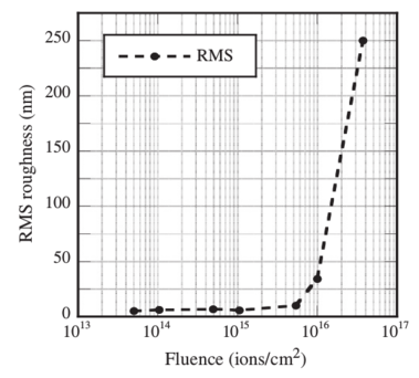 Figure 1:
Plot of RMS surface roughness as a function of fluence for the 550 °C
annealed films irradiated with 10 MeV Au 3+ ions.
Figure 1:
Plot of RMS surface roughness as a function of fluence for the 550 °C
annealed films irradiated with 10 MeV Au 3+ ions.
|
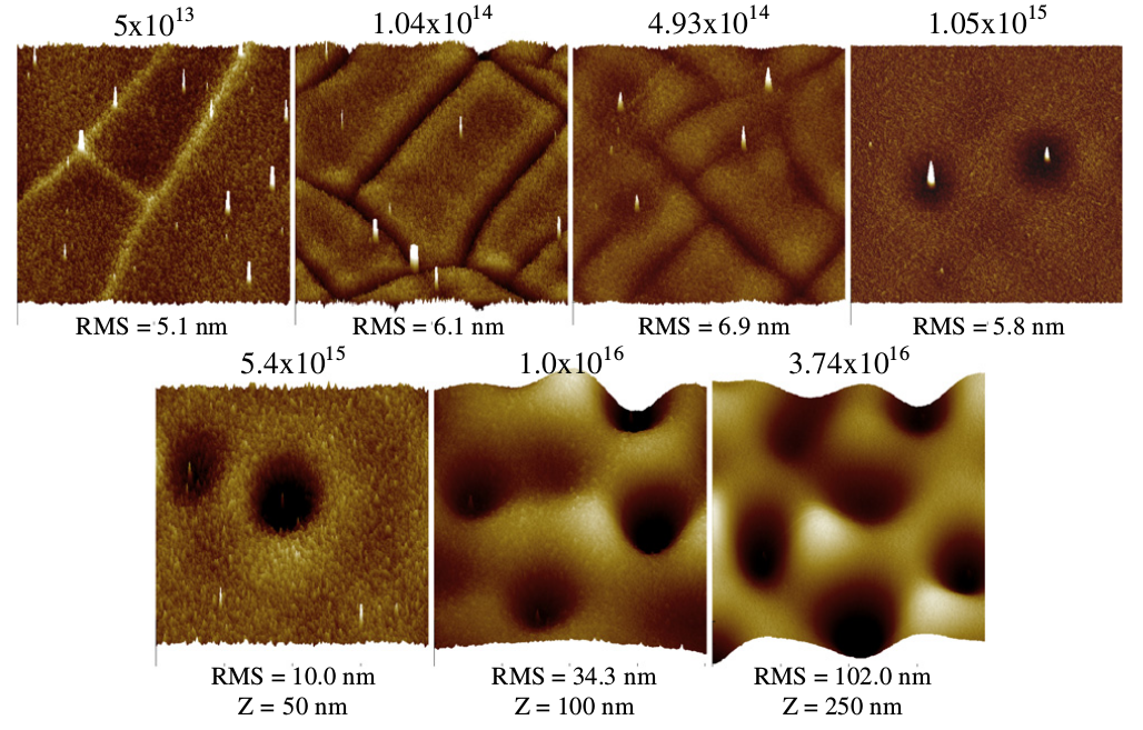
After irradiation, the AFM results revealed a roughing of the surface
(shown in Fig. 1), increase in crack density, crack healing, and
finally significant modification as the fluence increased (Fig. 2).
Initially at the lowest fluences the crack density increased and the
crack profile inverted. At 1 × 10¹⁴ ions/cm2,
the edges of the cracks
became rounded out-of-plane. At ~5 × 10¹⁴ ions/cm2
not only was
the crack density greater, the edge rounding increased and depressions
in the surface containing a central peak appeared. When the
fluence was increased to 1 × 10¹⁵ ions/cm2
the cracks disappeared,
at least at the surface. The round depressions or craters were
deeper and the central peaks more prominent. Note that these
depressions are large (8-12 μ m in diameter) and possess well-defined
ridges. The craters at all fluences were non-uniformly distributed
across the sample surfaces. Interestingly, the height of its
central peak did not correlate with the depth of its crater, that is
very tall peaks were observed in both deep and shallow craters.
Likewise relatively short peaks were found in deep craters. Further
increase in fluence resulted in an increased density and deepening
of the craters, although their diameters remained approximately
the same. Even though the average depth of the craters did increased
with fluence, there was variation in depth between craters
on the same sample. At the highest density of craters, the ridges
that defined their perimeters were no longer distinguishable and
the RMS roughness increased to 20 times that of the sample irradiated
at the lowest fluence. It is also important to note that the
depth of the craters at the three highest fluences exceeded the
50 nm thickness of the top HfO2 layer. At the highest fluence some
of the craters were over 400 nm deep, i.e. 8 times the thickness of
that layer.
 Figure 2:
40 × 40 μm AFM profile images of the 550 °C annealed tri-layer
films surface as a function of fluence. Note: the vertical
scale for the two highest fluences is 100 and
250 nm compared to 50 nm for the rest of the images.
Figure 2:
40 × 40 μm AFM profile images of the 550 °C annealed tri-layer
films surface as a function of fluence. Note: the vertical
scale for the two highest fluences is 100 and
250 nm compared to 50 nm for the rest of the images.
|
At intermediate fluences, the central peaks in the craters often
protrude above the surface, extending as much as 150 to 300 nm
from the base of the crater. Their measured contact angles ranged
from around 6 to 8 degrees up to nearly 30 degrees, depending on
the peak height.
Phase imaging revealed local changes in nano mechanical properties
as well. The peaks and the areas surrounding the craters appear
"softer" in the phase image than the base of the crater
suggesting compositional variations across the surface. This is consistent
with a non-uniform loss of HfO2 from the top layer observed
in TEM cross sectional data (not presented here).
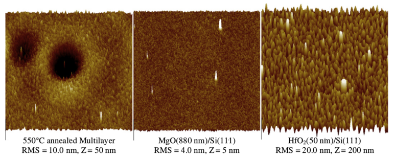 Figure 3:
40 × 40 μm AFM images showing a comparison of the surface modification
of the 550C annealed tri-layer film, a single MgO layer, and a single HfO2
layer after
irradiation with 5 × 10¹⁵ ions/cm2
10 MeV Au 3+ ions. Note the differences in RMS roughness and z vertical scales.
The single layer films are the same thickness as in the tri-layer film.
Figure 3:
40 × 40 μm AFM images showing a comparison of the surface modification
of the 550C annealed tri-layer film, a single MgO layer, and a single HfO2
layer after
irradiation with 5 × 10¹⁵ ions/cm2
10 MeV Au 3+ ions. Note the differences in RMS roughness and z vertical scales.
The single layer films are the same thickness as in the tri-layer film.
|
A comparison of the radiation tolerance toward surface modification
of the individual components of the tri-layer is shown in
Fig. 3. Although there was a change in the grain structure of the
MgO film, the RMS roughness did not increase after irradiation.
However, this was not the case for the HfO2 film, where the RMS
roughness increased at least 10-fold. However, even with this large
increase in roughness after irradiation, no craters were formed;
they were only observed on the tri-layer sample.
One final observation, a couple of AFM phase images and local
surface potential measurements (not shown), which were used to
try to determine if subsurface cracks persisted as the fluence was
increase, did reveal their existence but not in which layer, MgO
or the bottom HfO2 layer, or if they disappeared at the highest
fluences.
4. Discussion
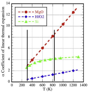 Figure 4:
Plots of the coefficient of linear thermal expansion as a function of
temperature for MgO and HfO2
[10],
and Si [11]. The left black line marks the
deposition T, while the right is approximately 550 °C.
Figure 4:
Plots of the coefficient of linear thermal expansion as a function of
temperature for MgO and HfO2
[10],
and Si [11]. The left black line marks the
deposition T, while the right is approximately 550 °C.
|
In order to understand the origin of cracking in the films annealed above
500 °C (753 K) one has to identify the probable origins.
The first factor is the different thermal responses of the
components that make up the tri-layer film and their substrate,
the largest component. Fig. 4 presents plots of the linear thermal
expansion coefficients, α, for MgO, HfO2, and silicon as a function
of temperature in degrees K over the relevant temperature range
used in the annealing process
[10,
11]. The black line on the left
indicates the deposition temperature. The one on the right indicates
the temperature where cracking was first observed. Clear
from this figure is the increasing disparity in the linear thermal
expansion properties between MgO and HfO2 and the silicon substrate.
At the film growth temperature MgO and silicon have similar values for
α. However, by 550 °C (823 K) the MgO value is
double that of the substrate. The situation is even worse when
you compare the value for HfO2 against MgO at that temperature.
The factor is almost 8 times greater for MgO than HfO2 .
The second potential candidate for driving cracking is the
change in volume of the HfO2 layers, particularly the trapped
bottom layer, during the transformation from an amorphous phase
to the monoclinic crystalline phase. Crystallization of HfO2 is
observed to begin around 500 °C and continue up to
800 °C [4,
5,
6],
the temperature at which crystallites were observed in the AFM
images. In addition, non-uniform crystallization at 550 °C would
lead to non-uniform strain in the films. Both factors could also induce cracking.
The situation is further complicated if heating the
polycrystalline MgO layer lead to further crystal growth.
The increase in number of cracks at the lower fluences could reduce
strain and aid dewetting between the MgO and HfO2 layers,
especially if these materials have significantly different surface
energies. Accurate measurement of the contact angle at the crack
edges are needed to help resolve this issue. However, the inversion
of the crack edge to form rounded, raised ridges increasing with
fluence is consistent with a dewetting mechanism.
The sudden onset of crack healing, at least in the top HfO2 layer,
when the fluence was doubled from 5 × 10¹⁴
to 1 × 10¹⁵ ions/cm2
and the formation of craters with a central peak is harder to explain
but appears to suggest a complicated intersection between
competing mechanisms, dewetting and a non-uniform strain field.
The non-uniform distribution of craters and crater sizes is consistent
with a variation in forces driven by non-uniform structure
and strain distribution.
The large size of the craters, increase in surface roughness, and
appearance of a central peak, which often extends above the surface,
does not point to a simple mechanism, especially if one considers
that the depth of craters is larger than the thickness of the
original top HfO2 layer and approaches a large fraction of the
tri-layer thickness. These dimensions require the loss or movement
of a significant proportion of both materials in the tri-layer. Phase
images also suggest that the inside of the crater wall is different
from the central peak and surrounding surface material and could
be a different phase. The lack of correlation between the crater
depth and the central peak height might also point to their formation
being decoupled in some way.
Irradiated of single-phase films of the two materials did not in
either case result in the formation of these unusual structures.
These experiments revealed totally different damage resistance.
Little change except in grain size was seen in the MgO film. In contrast
the HfO2 surface roughness increased 10 times. Since neither
formed craters with central peaks, this observation further points
to non-uniform strain and dewetting mechanisms in the tri-layer
structure grown on silicon.
We believe this is the first observation of crack healing and the
formation of large circular craters with central peaks in these
materials. The author could find no reference documenting the
appearance of radiation induced large, 8 to 12 μm diameter, craters
with central peaks protruding above the surface. Modeling efforts
are under way to understand the mechanisms behind both the
crack healing and the formation of the surface structures observed
by AFM techniques.
Acknowledgment
This work was supported by a Los Alamos National Laboratory,
Laboratory Directed Research and Development (LDRD) Grant.
References
- [1]
-
G.D. Jarvinen, D.W. Carroll, D.J. Devlin, United States Patent Application
No. S-100, (2004) 559.
- [2]
-
K.E. Sickafus, L. Minervini, R.W. Grimes, J.A. Valdez, M. Ishimaru, F. Li,
K.J. McClellan, T. Hartmann, Science 289 (5480) (2000) 748.
- [3]
-
P. Raschman, A. Fedorockoa, Chem. Eng. J. 117 (2006) 205.
- [4]
-
S. Nam, S.W. Nam, J.H. Yoo, and D.-H. Ko, Mat. Res. Soc. Symp. Proc.
716 B4.25.1 (2002).
- [5]
-
H. Wang, Y. Wang, J. Feng, C. Ye, B.Y. Wang, H.B. Wang, Q. Li,
Y. Jang, A.P. Huang, Z.S. Xiao, Appl. Phys. A 93 (2008) 681.
- [6]
-
G. He, M. Liu, L.Q. Zhu, M. Chang, Q. Fang, L.D. Zhang, Surf. Sci. 576 (2005) 67.
- [7]
-
T.L. Chen, X.M. Li, X. Zhang, W.D. Yu, X.D. Gao, Proc. of SPIE 5774 (2004) 361.
- [8]
-
J.H. Mazur, R. Gronsky, and J. Washburn, Solid-State Phys. 37, page unknown (1983).
- [9]
-
I.O. Usov, J.A. Valdez, J. Won, M. Hawley, D.J. Devlin, R.M. Dicerson, B.P. Uberuaga,
Y.Q. Wang, C.J. Reichhardt, G.D. Jarvinen, K.E. Sickafus, Nucl. Instrum.
Meth. Phys. Res. B 267 (2009) 1918.
- [10]
-
Y.S. Touloukian, R.K. Kirby, et al. (Eds.), Thermal Expansion - Metallic Elements
and Alloys. Thermophysical Properties of Matter: The TPRC Data Series, IFI/Plenum,
New York, 1975.
- [11]
-
H. Watanabe, N. Yamada, M. Okaji, Int. J. Thermophysics 25 (1) (2004) 221.
File translated from
TEX
by
TTHgold,
version 4.00.
Back to Home