Physical Review E 85, 056102 (2012)

Bidirectional sorting of flocking particles in the presence of asymmetric barriers

Jeffrey A. Drocco, C. J. Olson Reichhardt, and C. Reichhardt

Center for Nonlinear Studies and Theoretical Division, Los Alamos National Laboratory, Los Alamos, New Mexico 87545, USA

(Received 2 November 2011; published 3 May 2012)

We numerically demonstrate bidirectional sorting of flocking particles interacting with an array of V-shaped asymmetric barriers. Each particle aligns with the average swimming direction of its neighbors according to the Vicsek model and experiences additional steric interactions as well as repulsion from the fixed barriers. We show that particles preferentially localize to one side of the barrier array over time, and that the direction of this rectification can be reversed by adjusting the particle-particle exclusion radius or the noise term in the equations of motion. These results provide a conceptual basis for isolation and sorting of single- and multi-cellular organisms which move collectively according to flocking-type interaction rules.
I. INTRODUCTION
II. SIMULATION
III. RESULTS
IV. CONCLUSION
References


I.  INTRODUCTION

The ensemble dynamics of self-driven particles can differ significantly from those of Brownian random walkers . For example, in experiments on microfabricated habitats connected by funnel-shaped channels, self-propelled E. coli bacteria preferentially migrated to the chamber towards which the funnels pointed even though Brownian particles would have remained equally distributed in both chambers. A simple simulation model showed that the rectification arises due to the modification of the run-and-tumble swimming dynamics of the bacteria by the walls of the microenvironment . When a running bacterium encounters a wall, it does not reflect away from the wall or immediately tumble, but swims in the direction of the projection of its previous swimming vector along the wall. Refs. and [, ] found rectification under this interaction rule for independent swimmers that did not interact with each other. The rectification in the bacteria system resembles a ratchet effect in which a net dc motion occurs in the absence of a dc drive due to the application of an external ac drive or flashing substrate [6]. For self-driven particles, however, no external driving is necessary. In addition to demonstrations of directed bacterial motion achieved through a ratchet mechanism [7], it has also been shown that baths of swimming bacteria can induce directed rotational motion of asymmetric flywheels [8,9,10].
Interactions between self-propelled particles can lead to distinctive dynamical behaviors that are more complex than those of independently moving particles. Simple models such as that of Vicsek et al. [11,12] capture many features of the dynamics of species with strongly collective motion, in which individuals preferentially align with their neighbors and form moving groups [, ,, ]. These models qualitatively reproduce the motion of both macro-scale groups, such as fish schools and bird flocks [15,16], and micro-scale groups, such as bacterial swarms and cancerous tumors [, ]. The original Vicsek model includes only a term for preferential velocity alignment with all neighbors within a fixed flocking radius, yet it exhibits a phase transition to unidirectional motion as a function of particle density and noise amplitude. Although numerous modifications of the Vicsek model have been proposed, such as the addition of steric interactions [18] and/or cohesion [19,20,21,22], only a very limited amount of work has been done on the interaction of flocking particles with walls or barriers. Walls can impose a directional symmetry breaking [14], induce the formation of a vortex state [18,23,24,25] or laning [26], or simply serve as aggregation focal points [27]. Walls have also been used for understanding finite size effects [, ,, ,, ], such as the relationship between the collective dynamics of fish in a tank and those of fish in the open ocean.
In this work we simulate a modified version of the Vicsek flocking algorithm that includes both steric repulsion between particles and confinement within a two-dimensional microenvironment with strategically placed gates similar to those of Ref. [, ]. Unlike Ref. [, ], however, we consider strictly repulsive particle-wall interactions, so the particles do not follow the walls when swimming independently. As the particle density increases, we find rectification effects once the density is high enough to permit collective motion to occur. By varying the interparticle exclusion radius, the flocking radius, or the noise, we can reverse the direction of the rectification. This result has implications for the potential sorting of self-propelled particles that move according to these types of interaction rules.

II.  SIMULATION

We consider a two-dimensional L×L system of N self-driven particles at number density ρ0=N/L2 with fixed, repulsive boundaries on all sides. The overdamped equation of motion for a single particle i is dxi=vi(t)dt with
vi(t)=fvci(t)+fri(t)+fbi(t)
(1)
All quantities are rescaled to dimensionless units. The time step dt=0.002 and we take L=66. The alignment or velocity consensus force fvci [, ,, ] is determined by the velocities of all M particles, including particle i, within a flocking radius rf of particle i:
fvci(t)=Af
cos(Φvci(t))
^
x
 
+sin(Φvci(t))
^
y
 

(2)
with
Φvci(t)=arg
M

j=1 
vj(tdt)
(3)
where arg(b) indicates the angle of a vector b in polar coordinates. Here Af=2.0 and ξ is a random variable uniformly distributed on the interval [−η/2,η/2]. The velocity of an isolated particle is v=Afdt=0.004, placing us in the low velocity limit where flocks can occur in the absence of cohesive interactions [, ]. Both the steric particle-particle interactions fri and the particle-barrier interactions fbi are given by the stiff spring repulsions: fri(t)=∑jiNAr(2rerij)Θ(2rerij)rij and fbi(t)=∑kNgAp(re+rgrik)Θ(re+rgrik)rik, where Ar=200, Ap=10, rij=|ri(t)−rj(t)|, rij=[ri(t)−rj(t)]/rij, and Θ is the Heaviside function. Here re is the particle exclusion radius, rg=0.05 is the barrier exclusion radius, and there are Ng=16 barriers composed of the four confining walls plus 12 V-shaped gates. We define the barriers as line segments with a finite exclusion radius in order to provide a rounded end of the barrier with which particles can collide. rik is the vector from the nearest point on barrier k to particle i, rik=|rik|, and rik=rik/rik. The length of each side of the V gates is LB=4.9 and the angle each V arm makes with the y axis is 30°. The spacing between the bases of the V's is ls=5.5 and the spacing between the tips of adjacent V's is lo=0.6. The 12 gates bisect the system into top and bottom chambers, with the aperture of each funnel shape pointing toward the top chamber (see Fig. 1). We initialize the system by distributing the particles at random throughout the sample. The equations of motion are then integrated for 3×10⁶ simulation time steps.
Fig1.png
Figure 1: (Color online) Simulation images. Lines: barriers and walls; dots: particle positions. (a) Initial state of sample with rf=1.0, η = 0.7, and re=0.07 at ρ0=0.4. (b) The same sample after 7×10⁵ simulation time steps shows rectification of particles into the top chamber.

III.  RESULTS

In Fig. 1(a), we show an image of the simulation geometry in the randomly initialized state for a system with rf=1.0, re=0.07, and ρ0=0.4, corresponding to M=1742 total particles. After a sufficient amount of time elapses, the particles concentrate in one of the two chambers, reaching a steady state value of ρtop, the density in the top chamber. In Fig. 1(b), after 7×10⁵ simulation time steps the particle density is clearly higher in the top chamber.
Fig2.png
Figure 2: ρtop, the density in the top chamber, after 3×10⁶ simulation time steps for a sample with initial density ρ0=0.4, indicated by the dashed line. (a) ρtop vs re for η = 1.5 and rf=1.0. The rectification reverses at re=0.12 and drops to zero for re ≥ 0.3. (b) ρtop vs η for re=0.12 and rf=1.0. The rectification reverses at η ∼ 1.0 and drops to zero for η >~π. (c) ρtop vs rf for re=0.12 and η = 1.5. For rf < re only steric particle interactions occur and rectification is negligible. For re < rf < 1.2 rectification is toward the bottom chamber, followed by a rectification reversal at rf ≈ 1.2. For large rf, all the particles tend to align into a giant flock and accumulate in the top chamber.
Fig3.png
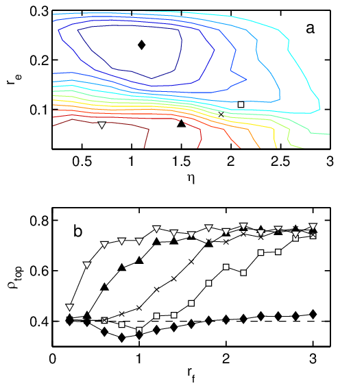
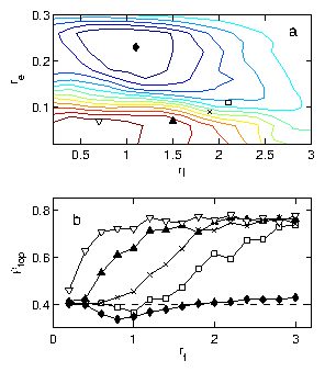
Figure 3: (Color online) Dependence of rectification behavior on re, η, and rf for a sample with ρ0=0.4. (a) Rectification phase diagram for re vs η with rf fixed at rf=1.0. Contours indicate lines of constant ρtop. Lower contours (red) indicate rectification into the top chamber and upper contours (blue) indicate rectification to the bottom chamber. (b) Rectification curves showing ρtop after 4×10⁵ time steps in the same system as a function of rf for various selections of re and η: re=0.23, η = 1.1 (black lozenges); re=0.11, η = 2.1 ([¯]); re=0.09, η = 1.9 (x); re=0.07, η = 1.5 (black triangles); re=0.07, η = 0.7 (big down triangles). The initial density ρ0=0.4 is indicated by a dashed line. The location of each curve on the re vs η phase diagram in (a) is indicated by the corresponding symbol; the point corresponding to the lowest curve (black lozenges) sits at the maximum of reversed rectification, and the remaining points ([¯], x, black triangles, and big down triangles) successively ascend the landscape to the peak of forward rectification.
We find that we can vary whether the rectification moves the particles into the top (ρtop > ρ0) or bottom (ρtop < ρ0) chamber by altering re, η, or rf, as shown in Fig. 2(a-c) where we plot ρtop after 3×10⁶ simulation time steps. For small values of re and η, particles are rectified into the top chamber, but a rectification reversal occurs at re=0.12 and η ∼ 1.0 in Fig. 2(a) and (b), respectively. There is a saturation into a nonrectifying state for re ≥ 0.3 in Fig. 2(a); this corresponds to 2relo and occurs when the particle diameter becomes larger than the aperture between adjacent gates, so that particles can no longer pass between the upper and lower chambers. In Fig. 2(b) rectification vanishes for η >~π when the alignment force between neighboring particles is almost completely destroyed by noise. The dependence of rectification on the flocking radius rf is qualitatively different. Fig. 2(c) indicates that no rectification occurs when rf < re. In this limit, the particles interact only sterically and have no flocking interaction, and the repulsive barrier walls produce no rectification in the absence of flocking. At fixed re=0.12, for rf < 1.2, we find a reversed rectification into the lower chamber, while for rf ≥ 1.2, the particles rectify into the top chamber. For rf > 2.0, the value of ρtop saturates at ρtop=0.8=2ρ0, indicating that nearly all of the particles are located in the top chamber.
We plot a rectification phase diagram as a function of re and η in Fig. 3(a), showing that rectification into the upper chamber occurs for small values of re and η, while reversed rectification into the lower chamber appears for larger re and slightly larger η. We find that for some combinations of η and re, both forward and reversed rectification states appear as rf is varied (Fig. 3(b), \blacklozenge and [¯]), while for other combinations of η and re, only forward rectification appears (Fig. 3(b), \blacktriangle and \bigtriangledown).
Fig4.png
Figure 4: (Color online) Illustration of rectification into the top chamber for low noise η = 1.5 and small exclusion radius re=0.05 at rf=1.0 in a sample with ρ0=0.4. A 15×15 section of the sample is shown. Dots: particle positions; light lines: particle trajectories; heavy lines: barriers. A flock incident on the gates from the bottom chamber (a) condenses and elongates in order to file through the aperture between gates (b). Flocks incident on the gates from the top chamber have a much lower probability of passing through the aperture and cannot be funneled into a similar oblong shape.
Fig5.png
Figure 5: (Color online) Illustration of rectification into the lower chamber for low noise η = 1.5 and large exclusion radius re=0.2 at rf=1.0 in a sample with ρ0=0.4. A 20×20 section of the sample is shown. Dots: particle positions; light lines: particle trajectories; heavy lines: barriers. (a,b) Flocks incident on gates from the bottom chamber cannot fit through the aperture for this value of re; the flock jams inside the funnel while a single particle (highlighted in red) escapes from the flock and enters the upper chamber. The remainder of the flock returns to the lower chamber. (c,d,e) Flocks incident on gates from the top chamber are fragmented and a small group of particles (highlighted in red) can escape from the flock and enter the lower chamber. The flock fragmentation process occurs with greater frequency as the flocks become less cohesive due to either higher η or higher ratios re/rf.
The rectification reversal occurs due to a change in the nature of the microscopic interaction between the flocks and the funnel channels. For example, as the exclusion radius re increases, the particles are less able to form tight and cohesive flocks. At low values of re, particles are rectified into the top chamber when flocks, incident on the gates from the bottom, rearrange into oblong shapes and pass efficiently through the funnel, as illustrated in Fig. 4. For higher values of re, the steric interparticle repulsion prevents the flocks from condensing and makes it impossible for more than one particle at a time to pass through the funnel aperture. As a result, the particles clog inside the funnel rather than passing through, as illustrated in Fig. 5(a). The flock reverses direction due to the repulsion from the barrier walls, and at most one or two particles occasionally manage to escape the flock and enter the top chamber, as shown in Fig. 5(b). In contrast, a flock that approaches the gates from the upper chamber is fragmented by the gates into two smaller flocks; when this occurs, particles that are directly incident on the aperture between gates can escape from both flocks and pass in a single file into the lower chamber, as illustrated in Fig. 5(c-e). Since the average number of particles escaping the flock and crossing the barrier is larger when the flocks are approaching from above than when they are approaching from below, a net rectification into the lower chamber occurs over time.
We note that the reversed rectification into the lower chamber (Fig. 5) is a much slower process than the forward rectification into the higher chamber (Fig. 4). This is illustrated in Fig. 6(a). In the case of forward rectification, ρtop reaches a saturation value within 2000 simulation time steps, though large fluctuations in ρtop persist due to the condensation of the particles into flocks containing many members, which transit the gates simultaneously. In the reversed case, by contrast, the rectification occurs via transits of individual or small numbers of particles rather than large flocks. As a result, the reverse rectification is both smoother and significantly slower than the forward rectification, and the sample does not reach a saturation value of ρtop until after 15000 simulation time steps. We find that the amount of rectification as measured by the value of ρtop at the end of the simulation time is not sensitive to sample size L provided that the system is allowed to reach the saturated steady state, as illustrated in Fig. 6(b). The forward rectification is very rapid so we find no variation in the final ρtop value as we vary L. The reverse rectification is much slower, and the saturation time increases with increasing L. As a result, if we run the simulation for a fixed time of 3 ×10⁶ simulation time steps that is shorter than the saturation time, the final value of ρtop decreases with increasing L in the reverse rectification regime, as shown in the inset of Fig. 6(b), simply because the larger systems are further from saturation at this time. If we instead run the simulation for 8 ×10⁶ simulation time steps, well into saturation, the final value of ρtop is insensitive to sample size just as in the forward rectification case, as seen in the inset of Fig. 6(b).
Fig6.png
Figure 6: (Color online) (a) Particle density ρtop in top chamber as a function of time for samples with η = 1.5, rf=1.0, and ρ0=0.4. Solid lines: re=0.05 and 0.07 produce forward rectification. Dashed lines: re=0.21 and 0.23 produce reverse rectification. (b) Rectification curves for low noise η = 1.5 and exclusion radii re ∈ [0.01,0.31] at rf=1.0 in a sample with ρ0=0.4. Density in the top chamber ρtop is shown after 3×10⁶ simulation time steps for L=33 (blue ◊), L=44 (green x), L=66 (yellow big up triangles), and L=99 (brown big circles). Longer time simulations are also shown: ρtop after 8×10⁶ simulation time steps for L=33 (cyan [¯]), and L=66 (red big down triangles). Inset: Mean final density in the top chamber under conditions of rectification toward the bottom, ρtopr=〈ρtop0.19 < re < 0.25, for various system sizes L and simulation times 3×10⁶ time steps (◊) and 8×10⁶ time steps (*).
Fig7.png
Figure 7: (Color online) Mean flock size Nc, in number of particles, vs rf for re=0.12 and η = 1.5 (blue circles), vs re for rf=1.0 and η = 1.5 (red squares), and vs η for rf=1.0 and re=0.12 (green diamonds). All samples have ρ0=0.4. Filled symbols indicate rectification toward the top chamber, while empty symbols indicate rectification toward the bottom. Error bars indicate standard deviation.
As noted above, the forward and reversed rectification mechanisms are qualitatively different: the former tends to occur when flocks are dense and malleable, while the latter tends to occur whenever the flocks become fragile or prone to breakage. This occurs both when the noise parameter η is increased and when the flocking radius rf is reduced. Under these conditions, the flocks are not cohesive enough to flow as a unit through the funnel aperture in the manner illustrated in Fig. 4; at the same time, the probability that a flock will fragment and lose some of its members to the lower chamber when approaching the gates from above, as in Fig. 5(c-e), is increased. Previous work on the pure Vicsek model showed that the system tends to form intermittent flocks in the ordered phase . To understand more quantitatively the relationship between flock cohesiveness and the rectification behavior, we analyze the tendency of the particles to form transient clusters in the various regimes of the model. In Fig. 7, we plot the average flock size Nc as a function of rf, re, and η for the systems in Fig. 2(a-c). We separate the particles into clusters iteratively by identifying particles that are within the flocking radius rf of each other; Nc is then the average number of particles per cluster. The value of Nc is higher in regimes where the particles are rectified to the top of the container, and lower in the reversed rectification regime.
Fig8.png
Figure 8: (Color online) Dependence of rectification on initial particle number density ρ0 for a system with rf=1.0 and η = 1.1. (a) ρtop0 after 3×10⁶ simulation time steps vs re for different values of ρ0. From blue to red, ρ0=0.004 (◊), 0.01 ([¯]), 0.03 (x), 0.05 (\bigtriangleup), 0.08 (big down triangle), 0.1 (big circles), 0.12 (+). A rectification reversal emerges as ρ0 increases. (b) ρtop0 after 3×10⁶ simulation time steps vs ρ0 for re=0.05 (upper red curve) and re=0.23 (lower blue curve).
One of the unique aspects of the rectification behavior described here is that, unlike previous rectification phenomena reported for self-driven particles , it occurs only when the initial particle density ρ0 is high enough for flock formation to occur. In the limit of low ρ0, when the particles are moving independently and not able to form flocks, individual particles simply reflect off the barriers in a manner similar to inertial particles. This type of barrier interaction has been shown to produce no rectification in the noninteracting particle limit [, ], and as indicated in Fig. 8(a) we find no rectification at low densities ρ0 < 0.01. As ρ0 increases, both rectification and a rectification reversal emerge, and the amount of rectification saturates for ρ0 >~0.1, as shown in Fig. 8(b). We note that since ρ0 represents number density, rather than surface area covered, it is possible to have ρ0 > 1.

IV.  CONCLUSION

We have implemented a simple model of flocking particles in the presence of fixed, repulsive barriers, and find that such particles will concentrate on one side of a set of asymmetric V-shaped gates. The direction of the rectification can be reversed by modulating any of three parameters: the flocking radius rf, the exclusion radius re, or the noise parameter η. The existence of the rectification and its direction are determined by the ability of the particles to form flocks and the robustness of the flocks against breakage; in the low density limit, when no flocks appear, we find no rectification due to the purely repulsive interactions of the particles with the barrier walls. Thus, the rectification we observe arises strictly due to collective effects. The bi-directional rectification behavior we describe could be used to sort particles which tend to concentrate on different sides of the barrier [35]. This effect is similar to the sorting phenomenon observed by Mahmud et al. for cancer cells[, ]. We expect sorting devices based on these principles to have broad potential applications with regard to both biomedical diagnostics and therapeutics.
This work was carried out under the auspices of the NNSA of the U.S. DoE at LANL under Contract No. DE-AC52-06NA25396.


References

[1]
B. ten Hagen, S. van Teeffelen, and H. Löwen, J. Phys.: Condens. Mat. 23, 194119 (2011).
[2]
P. Galajda, J. Keymer, P. Chaikin, and R. Austin, J. Bacteriol. 189, 8704 (2007).
[3]
P. Galajda, J. Keymer, J. Dalland, S. Park, S. Kou, and R. Austin, J. Mod. Optics 55, 3413 (2008).
[4]
M.B. Wan, C.J.O. Reichhardt, Z. Nussinov, and C. Reichhardt, Phys. Rev. Lett. 101, 018102 (2008).
[5]
J. Tailleur and M.E. Cates, EPL 86, 60002 (2009).
[6]
P. Reimann, Phys. Rep. 361, 57 (2002).
[7]
B. Kaehr and J.B. Shear, Lab Chip 9, 2632 (2009).
[8]
R. Di Leonardo, L. Angelani, D. Dell'Arciprete, G. Ruocco, V. Iebba, S. Schippa, M.P. Conte, F. Mecarini, F. De Angelis, and E. Di Fabrizio, Proc. Natl. Acad. Sci. (USA) 107, 9541 (2010).
[9]
A. Sokolov, M.M. Apodaca, B.A. Grzyboski, and I.S. Aranson, Proc. Natl. Acad. Sci. (USA) 107, 969 (2010).
[10]
L. Angelani, R. Di Leonardo, and G. Ruocco, Phys. Rev. Lett. 102, 048104 (2009).
[11]
T. Vicsek, A. Czirók, E. Ben-Jacob, I. Cohen, and O. Shochet, Phys. Rev. Lett. 75, 1226 (1995).
[12]
A. Czirók, H.E. Stanley, and T. Vicsek, J. Phys. A: Math. Gen. 30, 1375 (1997).
[13]
J. Toner, Y. Tu, Phys. Rev. Lett. 75, 4326 (1995).
[14]
J. Toner, Y. Tu, Phys. Rev. E 58, 4828 (1998).
[15]
D.J.T. Sumpter, Phil. Trans.: Biol. Sci. 361, 5 (2006).
[16]
I.D. Couzin, Trends Cognit. Sci. 13, 36 (2009).
[17]
T.S. Deisboeck and I.D. Couzin, Bioessays 31, 190 (2009).
[18]
A. Czirók, E. Ben-Jacob, I. Cohen, and T. Vicsek, Phys. Rev. E 54, 1791 (1996).
[19]
I.D. Couzin, J. Krause, R. James, G.D. Ruxton, and N.R. Franks, J. Theor. Biol. 218, 1 (2002).
[20]
G. Gregoire, H. Chate, and Y. Tu, Physica D 181, 157 (2003).
[21]
G. Grégoire and H. Chaté, Phys. Rev. Lett. 92, 025702 (2004).
[22]
M.R. D'Orsogna, Y.L. Chuang, A.L. Bertozzi, and L.S. Chayes, Phys. Rev. Lett. 96, 104302 (2006).
[23]
Y.L. Duparcmeur, H. Herrmann, and J.P. Troadec, J. Phys. I France 5, 1119 (1995).
[24]
B. Szabó, G.J. Szöllösi, B. Gönci, Zs. Jurányi, D. Selmeczi, and T. Vicsek, Phys. Rev. E 74, 061908 (2006).
[25]
A.B.T. Barbaro, K. Taylor, P.F. Trethewey, L. Youseff, and B. Birnir, Math. Comput. Sim. 79, 3397 (2009).
[26]
J.P. Hernandez-Ortiz, P.T. Underhill, and M.D. Graham, J. Phys.: Condens. Matter 21, 204107 (2009).
[27]
J.P. Hernandez-Ortiz, C.G. Stoltz, and M.D. Graham, Phys. Rev. Lett. 95, 204501 (2005).
[28]
D.J. Hoare, I.D. Couzin, J.-G.J. Godin, and J. Krause, Animal Behav. 67, 155 (2004).
[29]
E. Hensor, I.D. Couzin, R. James, and J. Krause, Oikos 110, 344 (2005).
[30]
C.K. Hemelrijk, H. Hildenbrandt, J. Reinders, and E.J. Stamhuis, Ethology 116, 1099 (2010).
[31]
R. Olfati-Saber, IEEE Trans. on Automatic Control 51, 401 (2006).
[32]
Z. Cheng, H.T. Zhang, M.Z.Q. Chen, T. Zhou, and N.V. Valeyev, PLOS One 6, e22123 (2011).
[33]
M. Nagy, I. Daruka, and T. Vicsek, Physica A 373, 445 (2007).
[34]
C. Huepe and M. Aldana, Phys. Rev. Lett. 92, 168701 (2004).
[35]
See Supplemental Material at http://link.aps.org/supplemental/10.1103/PhysRevE.85.056102 for a demonstration of two-species sorting.
[36]
G. Mahmud, C.J. Campbell, K.J.M. Bishop, Y.A. Komarova, O. Chaga, S. Soh, S. Huda, K. Kandere-Grzybowska, and B.A. Grzybowski, Nature Phys. 5, 606 (2009).


File translated from TEX by TTHgold, version 4.00.

Back to Home